Page 2155 of 2898
SEM071FA
SEM110G
6. Remove engine gussets.
Refer to MT-24 or AT-355, ªInstallationº.
7. Remove rear plate cover (A/T models).
SEM365EB
8. Remove oil pan.
a. Insert Tool between cylinder block and oil pan.
1)Be careful not to damage aluminum mating face.
Do not insert screwdriver, or oil pan flange will be dam-
aged.
b. Slide Tool by tapping on the side of the Tool with a hammer.
SEM295C
InstallationNJEM00101. Use a scraper to remove old liquid gasket from mating surface
of oil pan.
+Also remove old liquid gasket from mating surface of cyl-
inder block.
SEM015E
2. Apply a continuous bead of liquid gasket to mating surface of
oil pan.
+Use Genuine Liquid Gasket or equivalent.
+Apply to groove on mating surface.
+Allow 7 mm (0.28 in) clearance around bolt holes.
OIL PANQG
Removal (Cont'd)
EM-21
Page 2156 of 2898
SEM259G
+Be sure liquid gasket diameter is 3.5 to 4.5 mm (0.138 to
0.177 in).
+Attaching should be done within 5 minutes after coating.
SEM072F
3. Install oil pan.
+Tighten oil pan nuts and bolts in the numerical order.
+Wait at least 30 minutes before refilling engine oil.
4. Install parts in reverse order of removal.
OIL PANQG
Installation (Cont'd)
EM-22
Page 2157 of 2898
ComponentsNJEM0011
YEM012
1. Chain tensioner
2. Camshaft sprocket (Intake)
3. Camshaft sprocket (Exhaust)
4. O-ring
5. Slack side timing chain guide
6. Timing chain tension guide7. Timing chain
8. Crankshaft sprocket
9. Oil pump drive spacer
10. Front cover
11. O-ring
12. Oil seal13. Crankshaft pulley
14. Cylinder head front cover
15. Camshaft position sensor
(PHASE)
16. Cylinder block dowels
TIMING CHAINQG
Components
EM-23
Page 2158 of 2898

CAUTION:
+After removing timing chain, do not turn crankshaft and
camshaft separately, or valves will strike piston heads.
+When installing chain tensioner, oil seats, or other sliding
parts, lubricate contacting surfaces with new engine oil.
+Apply new engine oil to bolt threads and seat surfaces
when installing camshaft sprocket and crankshaft pulley.
+When removing oil pump assembly, remove camshaft
position sensor (PHASE), then remove timing chain from
engine.
+Be careful not to damage sensor edges.
SEM869F
RemovalNJEM01051. Drain engine coolant from radiator and cylinder block.
Be careful not to spill coolant on drive belts.
2. Remove reservoir tank.
3. Release fuel pressure.
Refer to EC-40, ªFuel Pressure Releaseº.
4. Remove the following belts.
+Power steering pump drive belt
+Alternator drive belt
5. Remove front right-side wheel.
6. Remove front/right splash undercover.
7. Remove front exhaust tube.
SEM870F
8. Remove vacuum hoses, fuel hoses, and so on.
9. Remove ignition coils.
10. Remove spark plugs.
SEM102G
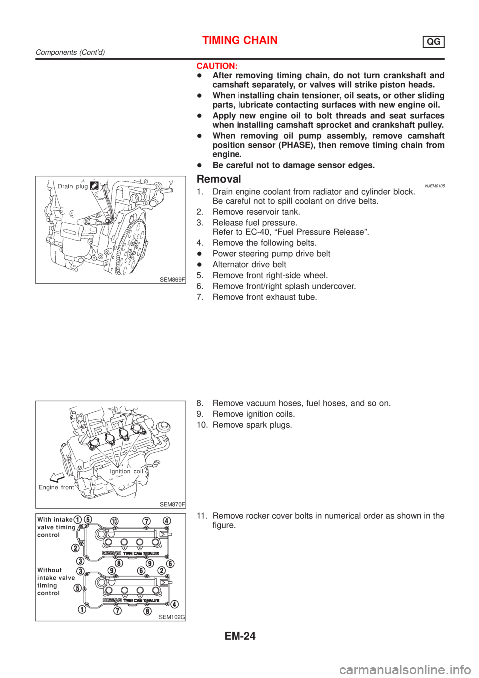
11. Remove rocker cover bolts in numerical order as shown in the
figure.
TIMING CHAINQG
Components (Cont'd)
EM-24
Page 2160 of 2898
SEM008G
20. Remove cylinder head bolts at engine front side.
SEM879F
21. Remove oil pan. Refer to EM-20, ªRemovalº.
22. Remove oil strainer.
SEM880F
23. Remove starter motor, and set ring gear stopper using mount-
ing bolt holes.
SEM881F
24. Loosen crankshaft pulley bolt.
25. Remove crankshaft pulley with a suitable puller.
SEM103G
26. Remove RH engine mounting.
TIMING CHAINQG
Removal (Cont'd)
EM-26
Page 2161 of 2898
SEM104G
27. Remove RH engine mounting bracket.
28. Remove idler pulley and bracket.
SEM883F
29. Remove water pump pulley and water pump.
30. Remove front cover bolts and front cover as shown.
H1: Located on water pump
H2: Located on power steering pump adjusting bar
+Inspect for oil leakage at front oil seal. Replace seal if oil leak
is present.
SEM884F
SEM897F
31. Remove timing chain.
32. Remove oil pump drive spacer.
33. Remove chain guides.
34. Remove crankshaft sprocket.
35. Remove O-rings from cylinder block and front cover.
SEM885F
InspectionNJEM0106Check for cracks and excessive wear at roller links. Replace
if necessary.
TIMING CHAINQG
Removal (Cont'd)
EM-27
Page 2163 of 2898
SEM519G
6. Install camshaft sprocket bolts and tighten them to correct
torque.
+Apply new engine oil to bolt threads and seat surface.
SEM520G
7. Install chain tensioner.
+Before installing chain tensioner, insert a suitable pin into
pin hole of chain tensioner.
+After installing chain tensioner, remove the pin.
8. Install timing chain guide.
SEM893F
9. Install O-rings to cylinder block.
SEM894F
10. Before installing front cover, remove all traces of liquid gasket
from mating surface using a scraper.
+Also remove traces of liquid gasket from mating surface of
cylinder block.
SEM677G
11. Apply a continuous bead of liquid gasket to mating surface of
front cover.
+Check alignment of mating marks on chain and crankshaft
sprocket.
+Align oil drive spacer with oil pump.
+Place timing chain to the side of chain guide. This pre-
vents the chain from making contact with water seal area
of front cover.
TIMING CHAINQG
Installation (Cont'd)
EM-29
Page 2164 of 2898

SEM896F
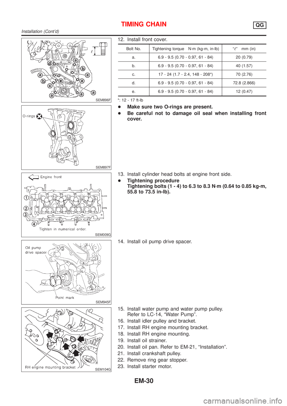
12. Install front cover.
Bolt No. Tightening torque N´m (kg-m, in-lb) ª!º mm (in)
a. 6.9 - 9.5 (0.70 - 0.97, 61 - 84) 20 (0.79)
b. 6.9 - 9.5 (0.70 - 0.97, 61 - 84) 40 (1.57)
c. 17 - 24 (1.7 - 2.4, 148 - 208*) 70 (2.76)
d. 6.9 - 9.5 (0.70 - 0.97, 61 - 84) 72.8 (2.866)
e. 6.9 - 9.5 (0.70 - 0.97, 61 - 84) 12 (0.47)
*: 12 - 17 ft-lb
SEM897F
+Make sure two O-rings are present.
+Be careful not to damage oil seal when installing front
cover.
SEM009G
13. Install cylinder head bolts at engine front side.
+Tightening procedure
Tightening bolts (1 - 4) to 6.3 to 8.3 N´m (0.64 to 0.85 kg-m,
55.8 to 73.5 in-lb).
SEM945F
14. Install oil pump drive spacer.
SEM104G
15. Install water pump and water pump pulley.
Refer to LC-14, ªWater Pumpº.
16. Install idler pulley and bracket.
17. Install RH engine mounting bracket.
18. Install RH engine mounting.
19. Install oil strainer.
20. Install oil pan. Refer to EM-21, ªInstallationº.
21. Install crankshaft pulley.
22. Remove ring gear stopper.
23. Install starter motor.
TIMING CHAINQG
Installation (Cont'd)
EM-30