Page 2165 of 2898
SEM887F
24. Install cylinder head front cover.
+Apply liquid gasket to cylinder head front cover.
+Use Genuine Liquid Gasket or equivalent.
SEM889F
25. Install camshaft position sensor (PHASE).
SEM888F
26. Before installing rocker cover, apply a continuous bead of liq-
uid gasket to mating surface of cylinder head.
SEM105G
27. Install rocker cover with rocker cover gasket and tighten bolts
in numerical order as shown in the figure.
28. Install spark plugs.
29. Install ignition coils.
30. Install front exhaust tube.
31. Install front/right splash undercover.
32. Install front right-side wheel.
33. Drive belts.
For adjusting drive belt deflection, refer to EM-16, ªCheckingº.
34. Reinstall parts in reverse order of removal.
TIMING CHAINQG
Installation (Cont'd)
EM-31
Page 2166 of 2898
SEM909F
ReplacementNJEM0015VALVE OIL SEALNJEM0015S011. Remove rocker cover.
2. Remove camshaft.
3. Remove valve spring. Refer to EM-37.
4. Remove valve oil seal with Tool.
Piston concerned should be set at TDC to prevent valve from
falling.
SEM910F
5. Apply new engine oil to new valve oil seal and install it with
Tool.
SEM911F
FRONT OIL SEALNJEM0015S021. Remove the following parts:
+Engine under cover
+RH engine side cover
+Alternator and power steering drive belts
+Crankshaft pulley
2. Remove front oil seal from front cover.
+Be careful not to scratch front cover.
SEM715A
SEM912F
3. Apply new engine oil to new oil seal and install it using a suit-
able tool.
+Install new oil seal in the direction shown.
OIL SEALQG
Replacement
EM-32
Page 2167 of 2898
SEM096F
REAR OIL SEAL=NJEM0015S031. Remove transaxle. Refer to MT-23 or AT-354, ªREMOVAL AND
INSTALLATIONº.
2. Remove flywheel or drive plate.
3. Remove rear oil seal.
+Be careful not to scratch rear oil seal retainer.
SEM715A
4. Apply new engine oil to new oil seal and install it using a suit-
able tool.
+Install new oil seal in the direction shown.
SEM097F
OIL SEALQG
Replacement (Cont'd)
EM-33
Page 2168 of 2898
ComponentsNJEM0108
SEM106G
1. Oil filler cap
2. Rocker cover
3. Rocker cover gasket
4. Intake valve timing control sole-
noid (Models with intake valve tim-
ing control)
5. Camshaft bracket
6. Intake camshaft7. Exhaust camshaft
8. Timing chain guide
9. Cylinder head bolt
10. Shim
11. Valve lifter
12. Valve cotter
13. Valve spring retainer
14. Valve spring15. Valve spring seat
16. Valve oil seal
17. Valve guide
18. Cylinder head
19. Cylinder head gasket
20. Valve seat
21. Valve
CYLINDER HEADQG
Components
EM-34
Page 2169 of 2898

CAUTION:
+When installing camshaft and oil seal, lubricate contacting
surfaces with new engine oil.
+When tightening cylinder head bolts, camshaft sprocket
bolts and camshaft bracket bolts, lubricate bolt threads
and seat surfaces with new engine oil.
+Attach tags to valve lifters so as not to mix them up.
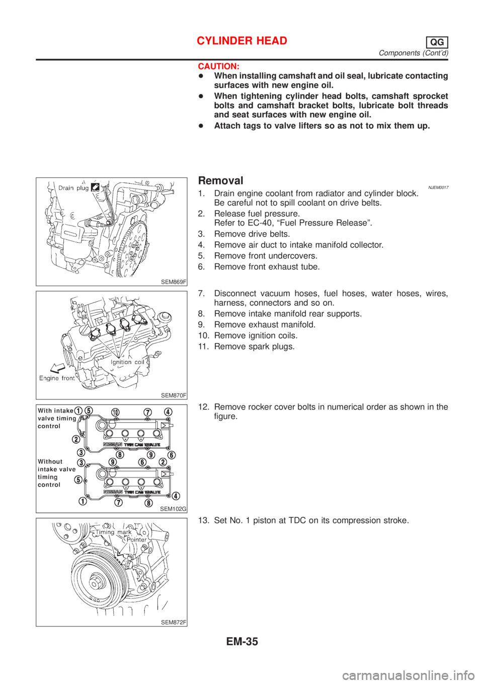
SEM869F
RemovalNJEM00171. Drain engine coolant from radiator and cylinder block.
Be careful not to spill coolant on drive belts.
2. Release fuel pressure.
Refer to EC-40, ªFuel Pressure Releaseº.
3. Remove drive belts.
4. Remove air duct to intake manifold collector.
5. Remove front undercovers.
6. Remove front exhaust tube.
SEM870F
7. Disconnect vacuum hoses, fuel hoses, water hoses, wires,
harness, connectors and so on.
8. Remove intake manifold rear supports.
9. Remove exhaust manifold.
10. Remove ignition coils.
11. Remove spark plugs.
SEM102G
12. Remove rocker cover bolts in numerical order as shown in the
figure.
SEM872F
13. Set No. 1 piston at TDC on its compression stroke.
CYLINDER HEADQG
Components (Cont'd)
EM-35
Page 2171 of 2898

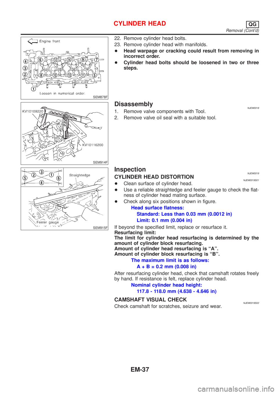
SEM878F
22. Remove cylinder head bolts.
23. Remove cylinder head with manifolds.
+Head warpage or cracking could result from removing in
incorrect order.
+Cylinder head bolts should be loosened in two or three
steps.
SEM914F
DisassemblyNJEM00181. Remove valve components with Tool.
2. Remove valve oil seal with a suitable tool.
SEM915F
InspectionNJEM0019CYLINDER HEAD DISTORTIONNJEM0019S01+Clean surface of cylinder head.
+Use a reliable straightedge and feeler gauge to check the flat-
ness of cylinder head mating surface.
+Check along six positions shown in figure.
Head surface flatness:
Standard: Less than 0.03 mm (0.0012 in)
Limit: 0.1 mm (0.004 in)
If beyond the specified limit, replace or resurface it.
Resurfacing limit:
The limit for cylinder head resurfacing is determined by the
amount of cylinder block resurfacing.
Amount of cylinder head resurfacing is ªAº.
Amount of cylinder block resurfacing is ªBº.
The maximum limit is as follows:
A + B = 0.2 mm (0.008 in)
After resurfacing cylinder head, check that camshaft rotates freely
by hand. If resistance is felt, replace cylinder head.
Nominal cylinder head height:
117.8 - 118.0 mm (4.638 - 4.646 in)
CAMSHAFT VISUAL CHECKNJEM0019S02Check camshaft for scratches, seizure and wear.
CYLINDER HEADQG
Removal (Cont'd)
EM-37
Page 2180 of 2898

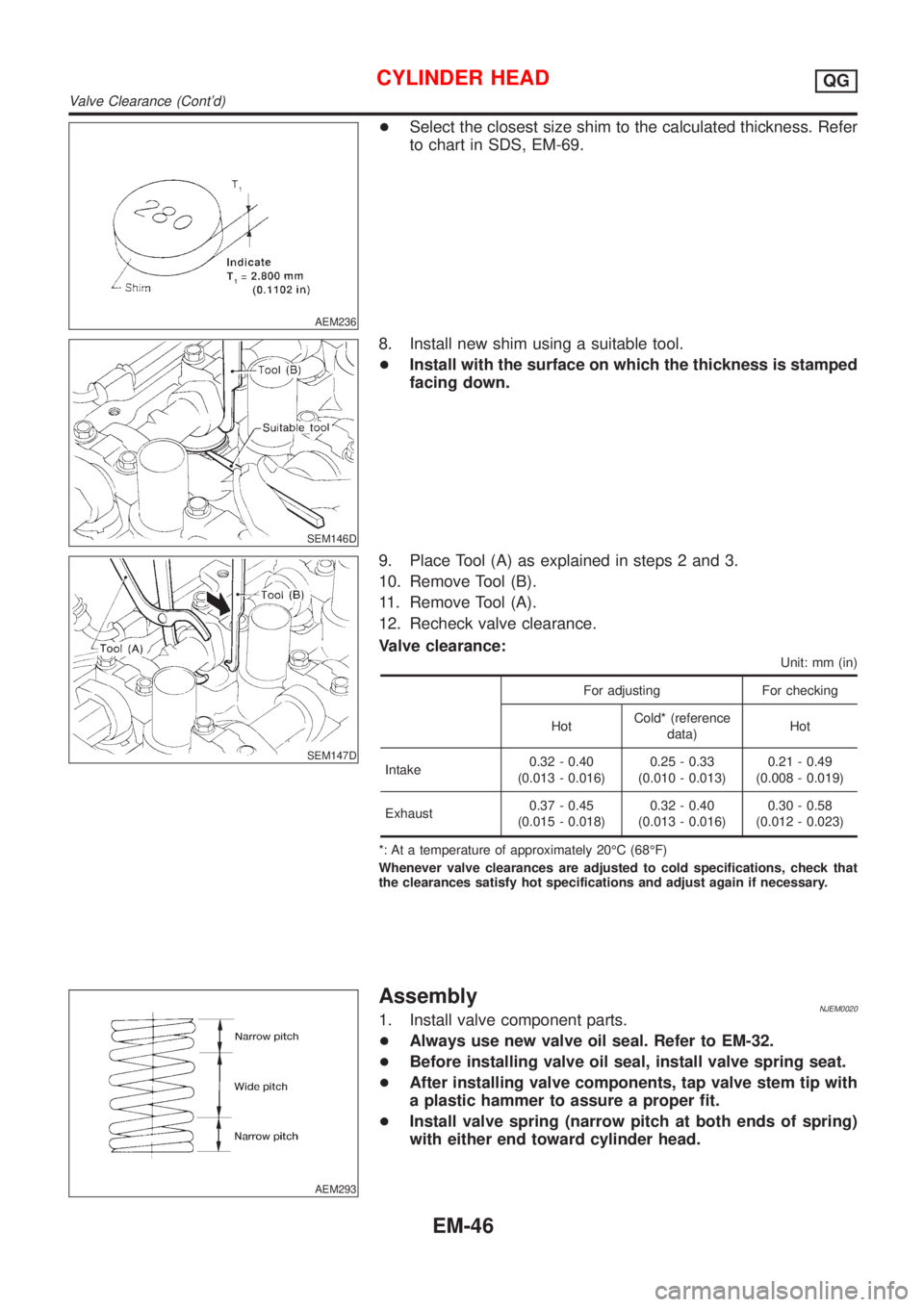
AEM236
+Select the closest size shim to the calculated thickness. Refer
to chart in SDS, EM-69.
SEM146D
8. Install new shim using a suitable tool.
+Install with the surface on which the thickness is stamped
facing down.
SEM147D
9. Place Tool (A) as explained in steps 2 and 3.
10. Remove Tool (B).
11. Remove Tool (A).
12. Recheck valve clearance.
Valve clearance:
Unit: mm (in)
For adjusting For checking
HotCold* (reference
data)Hot
Intake0.32 - 0.40
(0.013 - 0.016)0.25 - 0.33
(0.010 - 0.013)0.21 - 0.49
(0.008 - 0.019)
Exhaust0.37 - 0.45
(0.015 - 0.018)0.32 - 0.40
(0.013 - 0.016)0.30 - 0.58
(0.012 - 0.023)
*: At a temperature of approximately 20ÉC (68ÉF)
Whenever valve clearances are adjusted to cold specifications, check that
the clearances satisfy hot specifications and adjust again if necessary.
AEM293
AssemblyNJEM00201. Install valve component parts.
+Always use new valve oil seal. Refer to EM-32.
+Before installing valve oil seal, install valve spring seat.
+After installing valve components, tap valve stem tip with
a plastic hammer to assure a proper fit.
+Install valve spring (narrow pitch at both ends of spring)
with either end toward cylinder head.
CYLINDER HEADQG
Valve Clearance (Cont'd)
EM-46
Page 2181 of 2898

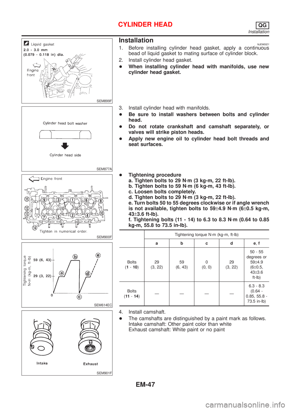
SEM899F
InstallationNJEM00211. Before installing cylinder head gasket, apply a continuous
bead of liquid gasket to mating surface of cylinder block.
2. Install cylinder head gasket.
+When installing cylinder head with manifolds, use new
cylinder head gasket.
SEM877A
3. Install cylinder head with manifolds.
+Be sure to install washers between bolts and cylinder
head.
+Do not rotate crankshaft and camshaft separately, or
valves will strike piston heads.
+Apply new engine oil to cylinder head bolt threads and
seat surfaces.
SEM900F
SEM614EC
SEM901F
+Tightening procedure
a. Tighten bolts to 29 N´m (3 kg-m, 22 ft-lb).
b. Tighten bolts to 59 N´m (6 kg-m, 43 ft-lb).
c. Loosen bolts completely.
d. Tighten bolts to 29 N´m (3 kg-m, 22 ft-lb).
e. Turn bolts 50 to 55 degrees clockwise or if angle wrench
is not available, tighten bolts to 59±4.9 N´m (6±0.5 kg-m,
43±3.6 ft-lb).
f. Tightening bolts (11 - 14) to 6.3 to 8.3 N´m (0.64 to 0.85
kg-m, 55.8 to 73.5 in-lb).
Tightening torque N´m (kg-m, ft-lb)
abcde,f
Bolts
(1-10)29
(3, 22)59
(6, 43)0
(0, 0)29
(3, 22)50-55
degrees or
59±4.9
(6±0.5,
43±3.6
ft-lb)
Bolts
(11-14)ÐÐÐÐ6.3 - 8.3
(0.64 -
0.85, 55.8 -
73.5 in-lb)
4. Install camshaft.
+The camshafts are distinguished by a paint mark as follows.
Intake camshaft: Other paint color than white
Exhaust camshaft: White paint or no paint
CYLINDER HEADQG
Installation
EM-47