2001 NISSAN ALMERA service
[x] Cancel search: servicePage 2136 of 2898
REPLACEMENT OF CONNECTING ROD
BUSHING (SMALL END)
..........................................62
FLYWHEEL/DRIVE PLATE RUNOUT........................62
Assembly ...................................................................62
PISTON..................................................................62
CRANKSHAFT.........................................................63
SERVICE DATA AND SPECIFICATIONS (SDS).........66
General Specifications ...............................................66
Compression Pressure ..............................................66
Belt Deflection............................................................67
Spark Plug .................................................................67
Cylinder Head ............................................................67
Valve ..........................................................................68
VALVE....................................................................68
VALVE SPRING.......................................................68
VALVE LIFTER........................................................68
VALVE CLEARANCE................................................69
VALVE GUIDE.........................................................69
AVAILABLE SHIMS..................................................69
VALVE SEAT...........................................................71
VALVE SEAT RESURFACE LIMIT.............................72
Camshaft and Camshaft Bearing ..............................72
Cylinder Block ............................................................73
Piston, Piston Ring and Piston Pin ...........................74
PISTON..................................................................74
PISTON RING.........................................................74
PISTON PIN............................................................74
Connecting Rod .........................................................75
Crankshaft..................................................................75
Main Bearing..............................................................75
STANDARD.............................................................75
UNDERSIZE............................................................75
Connecting Rod Bearing ...........................................76
STANDARD SIZE....................................................76
UNDERSIZE............................................................76
Bearing Clearance .....................................................76
Miscellaneous Components.......................................76
YD
PRECAUTIONS.............................................................77
Parts Requiring Angular Tightening ...........................77
Liquid Gasket Application Procedure ........................77
PREPARATION.............................................................78
Special Service Tools ................................................78
Commercial Service Tools .........................................80
NOISE, VIBRATION AND HARSHNESS (NVH)
TROUBLESHOOTING...................................................82
NVH Troubleshooting - Engine Noise .......................82
MEASUREMENT OF COMPRESSION PRESSURE....83
DRIVE BELTS................................................................85
Inspection...................................................................85
Adjustment .................................................................85
AIR CONDITIONER COMPRESSOR BELT................86
ALTERNATOR & WATER PUMP BELT.....................86
Removal .....................................................................86
Installation ..................................................................87
AIR CLEANER...............................................................88
Changing Air Cleaner Filter .......................................88
VISCOUS PAPER TYPE...........................................88
OIL PAN.........................................................................89
Components...............................................................89
Removal .....................................................................89
Installation ..................................................................91
TIMING CHAIN..............................................................94
Secondary Timing Chain ...........................................94
REMOVAL...............................................................94
INSPECTION...........................................................96
INSTALLATION........................................................96
Primary Timing Chain ................................................99
REMOVAL.............................................................100
INSPECTION.........................................................102
INSTALLATION......................................................102
INTAKE MANIFOLD....................................................107
Removal and Installation .........................................107
PREPARATIVE WORK...........................................107
FUEL PIPING........................................................108
INTAKE MANIFOLD...............................................108
EGR VOLUME CONTROL VALVE...........................108
WATER HOSE.......................................................108
Inspection.................................................................109
INTAKE MANIFOLD...............................................109
CATALYST.................................................................. 110
Removal and Installation ......................................... 110
PREPARATIVE WORK........................................... 110
CATALYST............................................................ 110
GUSSET............................................................... 111
EXHAUST MANIFOLD, TURBOCHARGER............... 112
Removal and Installation ......................................... 112
PREPARATIVE WORK........................................... 112
EXHAUST MANIFOLD AND TURBOCHARGER....... 112
EXHAUST MANIFOLD GASKET............................. 113
Disassembly and Assembly ..................................... 113
TURBOCHARGER................................................. 113
Inspection................................................................. 114
EXHAUST MANIFOLD........................................... 114
TURBOCHARGER................................................. 114
ROCKER COVER........................................................ 117
Removal and Installation ......................................... 117
PREPARATIVE WORK........................................... 117
ROCKER COVER.................................................. 117
CYLINDER HEAD........................................................ 119
Components............................................................. 119
Removal ...................................................................120
PREPARATIVE WORK...........................................120
CAMSHAFT...........................................................120
CYLINDER HEAD..................................................121
Disassembly.............................................................121
Inspection.................................................................122
CONTENTS(Cont'd)
EM-2
Page 2137 of 2898
CYLINDER HEAD DISTORTION.............................122
CAMSHAFT VISUAL CHECK..................................123
CAMSHAFT RUNOUT............................................123
CAMSHAFT CAM HEIGHT.....................................123
CAMSHAFT JOURNAL CLEARANCE......................123
CAMSHAFT END PLAY..........................................124
CAMSHAFT SPROCKET RUNOUT.........................124
VALVE GUIDE CLEARANCE..................................124
VALVE GUIDE REPLACEMENT..............................125
VALVE SEATS.......................................................126
REPLACING VALVE SEAT FOR SERVICE PARTS..126
VALVE DIMENSIONS.............................................128
VALVE SPRING.....................................................128
VALVE LIFTER......................................................128
Assembly .................................................................129
Installation ................................................................129
CYLINDER HEAD GASKET SELECTION.................130
CYLINDER HEAD BOLT DEFORMATION CHECK...131
CYLINDER HEAD-TO-BLOCK DIFFERENCE
CHECK
.................................................................131
LIQUID GASKET APPLICATION ON REAR CHAIN
CASE
....................................................................131
CYLINDER HEAD INSTALLATION..........................132
GLOW PLUG INSTALLATION.................................132
CAMSHAFT INSTALLATION...................................132
Valve Clearance.......................................................133
CHECKING...........................................................133
ADJUSTING..........................................................134
ENGINE ASSEMBLY...................................................137
Removal and Installation .........................................137
REMOVAL.............................................................138
INSTALLATION......................................................139
CYLINDER BLOCK.....................................................140
Components.............................................................140
Removal and Installation .........................................141
Disassembly.............................................................141
PISTON AND CRANKSHAFT..................................141
Inspection.................................................................144
CRANKSHAFT END PLAY.....................................144
CONNECTING ROD SIDE CLEARANCE.................144
PISTON AND PISTON PIN CLEARANCE................145
PISTON RING SIDE CLEARANCE..........................145
PISTON RING END GAP........................................145
CONNECTING ROD BEND AND TORSION.............146
CYLINDER BLOCK DISTORTION AND WEAR.........146
PISTON-TO-BORE CLEARANCE............................147
CRANKSHAFT.......................................................148
MAIN BEARING HOUSING INNER DIAMETER........149
BEARING CLEARANCE.........................................149
MAIN BEARING CRUSH HEIGHT...........................153
MAIN BEARING CAP BOLT DEFORMATION...........153
CONNECTING ROD BUSHING CLEARANCE
(SMALL END)
........................................................153
CONNECTING ROD BOLT DEFORMATION............154
FLYWHEEL RUNOUT............................................154
OIL JET................................................................154
OIL JET RELIEF VALVE.........................................154
Assembly .................................................................155
PISTON................................................................155
CRANKSHAFT.......................................................155
REPLACEMENT OF PILOT BUSHING.....................158
SERVICE DATA AND SPECIFICATIONS (SDS).......160
General Specifications .............................................160
Compression Pressure ............................................160
Belt Deflection..........................................................160
Cylinder Head ..........................................................160
Valve ........................................................................161
VALVE..................................................................161
VALVE CLEARANCE..............................................161
AVAILABLE SHIMS................................................161
VALVE SPRING.....................................................162
VALVE LIFTER......................................................162
VALVE GUIDE.......................................................163
Valve Seat................................................................164
Camshaft and Camshaft Bearing ............................166
Cylinder Block ..........................................................167
Piston, Piston Ring and Piston Pin .........................167
AVAILABLE PISTON..............................................167
PISTON RING.......................................................168
PISTON PIN..........................................................168
Connecting Rod .......................................................168
Crankshaft................................................................168
Available Main Bearing ............................................169
UNDERSIZE..........................................................169
Available Connecting Rod Bearing..........................169
CONNECTING ROD BEARING...............................169
UNDERSIZE..........................................................170
Miscellaneous Components.....................................170
BEARING CLEARANCE.........................................170
CONTENTS(Cont'd)
EM-3
Page 2139 of 2898
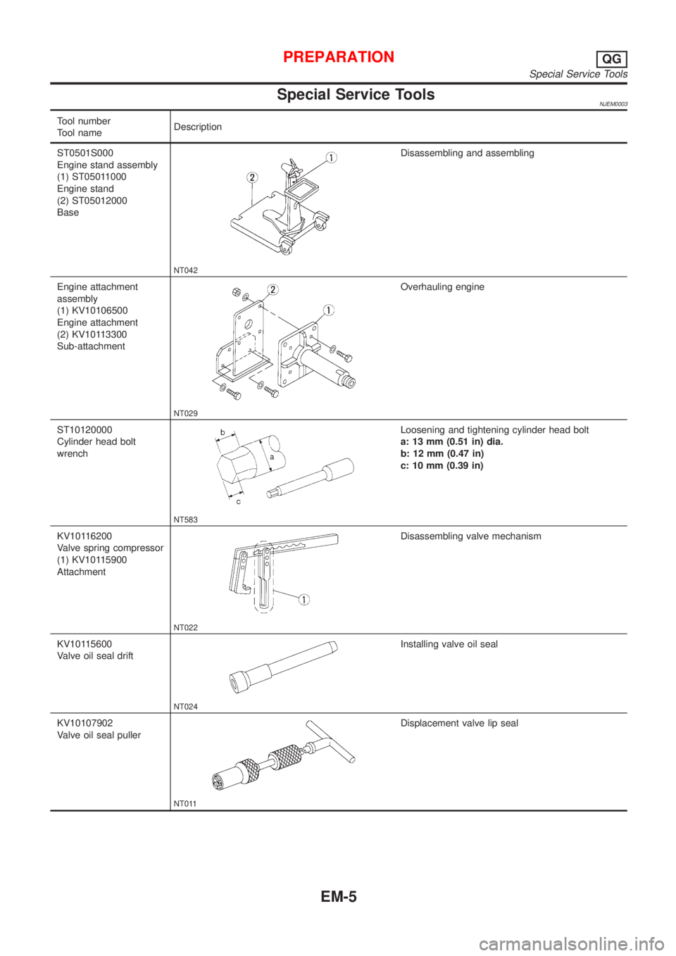
Special Service ToolsNJEM0003
Tool number
Tool nameDescription
ST0501S000
Engine stand assembly
(1) ST05011000
Engine stand
(2) ST05012000
Base
NT042
Disassembling and assembling
Engine attachment
assembly
(1) KV10106500
Engine attachment
(2) KV10113300
Sub-attachment
NT029
Overhauling engine
ST10120000
Cylinder head bolt
wrench
NT583
Loosening and tightening cylinder head bolt
a: 13 mm (0.51 in) dia.
b: 12 mm (0.47 in)
c: 10 mm (0.39 in)
KV10116200
Valve spring compressor
(1) KV10115900
Attachment
NT022
Disassembling valve mechanism
KV10115600
Valve oil seal drift
NT024
Installing valve oil seal
KV10107902
Valve oil seal puller
NT011
Displacement valve lip seal
PREPARATIONQG
Special Service Tools
EM-5
Page 2140 of 2898
Tool number
Tool nameDescription
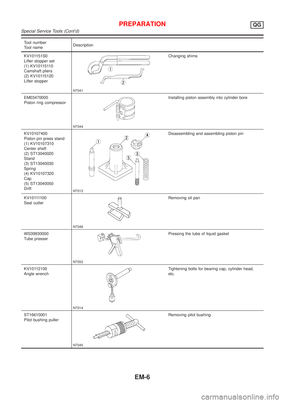
KV101151S0
Lifter stopper set
(1) KV10115110
Camshaft pliers
(2) KV10115120
Lifter stopper
NT041
Changing shims
EM03470000
Piston ring compressor
NT044
Installing piston assembly into cylinder bore
KV10107400
Piston pin press stand
(1) KV10107310
Center shaft
(2) ST13040020
Stand
(3) ST13040030
Spring
(4) KV10107320
Cap
(5) ST13040050
Drift
NT013
Disassembling and assembling piston pin
KV101111 0 0
Seal cutter
NT046
Removing oil pan
WS39930000
Tube presser
NT052
Pressing the tube of liquid gasket
KV10112100
Angle wrench
NT014
Tightening bolts for bearing cap, cylinder head,
etc.
ST16610001
Pilot bushing puller
NT045
Removing pilot bushing
PREPARATIONQG
Special Service Tools (Cont'd)
EM-6
Page 2141 of 2898
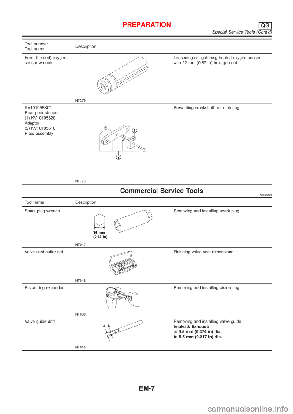
Tool number
Tool nameDescription
Front (heated) oxygen
sensor wrench
NT379
Loosening or tightening heated oxygen sensor
with 22 mm (0.87 in) hexagon nut
KV101056S0*
Rear gear stopper
(1) KV10105620
Adapter
(2) KV10105610
Plate assembly
NT773
Preventing crankshaft from rotating
Commercial Service ToolsNJEM0004
Tool name Description
Spark plug wrench
NT047
Removing and installing spark plug
Valve seat cutter set
NT048
Finishing valve seat dimensions
Piston ring expander
NT030
Removing and installing piston ring
Valve guide drift
NT015
Removing and installing valve guide
Intake & Exhaust:
a: 9.5 mm (0.374 in) dia.
b: 5.5 mm (0.217 in) dia.
PREPARATIONQG
Special Service Tools (Cont'd)
EM-7
Page 2142 of 2898

Tool name Description
Valve guide reamer
NT016
Reaming valve guide1or hole for oversize valve
guide2
Intake & Exhaust:
d
1: 5.5 mm (0.217 in) dia.
d
2: 9.685 mm (0.3813 in) dia.
Front oil seal drift
NT049
Installing front oil seal
a: 52 mm (2.05 in) dia.
b: 40 mm (1.57 in) dia.
Rear oil seal drift
NT049
Installing rear oil seal
a: 103 mm (4.06 in) dia.
b: 84 mm (3.31 in) dia.
Oxygen sensor thread
cleaner
NT778
Reconditioning the exhaust system threads before
installing a new oxygen sensor. Use with anti-
seize lubricant shown below.
a: 18 mm dia. with a pitch of 1.5 mm for Zirco-
nia Oxygen Sensor
b: 12 mm dia. with a pitch of 1.25 mm for Tita-
nia Oxygen Sensor
Anti-seize lubricant (Per-
matex
TM133AR or
equivalent meeting MIL
specification MIL-A-907)
NT779
Lubricating oxygen sensor thread cleaning tool
when reconditioning exhaust system threads
PREPARATIONQG
Commercial Service Tools (Cont'd)
EM-8
Page 2174 of 2898
SEM938C
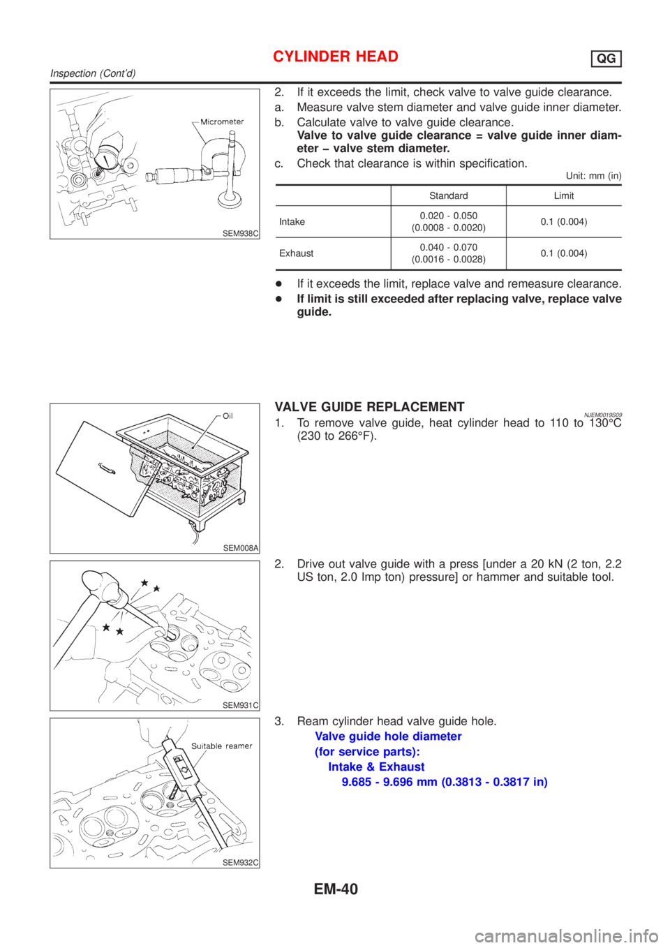
2. If it exceeds the limit, check valve to valve guide clearance.
a. Measure valve stem diameter and valve guide inner diameter.
b. Calculate valve to valve guide clearance.
Valve to valve guide clearance = valve guide inner diam-
eter þ valve stem diameter.
c. Check that clearance is within specification.
Unit: mm (in)
Standard Limit
Intake0.020 - 0.050
(0.0008 - 0.0020)0.1 (0.004)
Exhaust0.040 - 0.070
(0.0016 - 0.0028)0.1 (0.004)
+If it exceeds the limit, replace valve and remeasure clearance.
+If limit is still exceeded after replacing valve, replace valve
guide.
SEM008A
VALVE GUIDE REPLACEMENTNJEM0019S091. To remove valve guide, heat cylinder head to 110 to 130ÉC
(230 to 266ÉF).
SEM931C
2. Drive out valve guide with a press [under a 20 kN (2 ton, 2.2
US ton, 2.0 Imp ton) pressure] or hammer and suitable tool.
SEM932C
3. Ream cylinder head valve guide hole.
Valve guide hole diameter
(for service parts):
Intake & Exhaust
9.685 - 9.696 mm (0.3813 - 0.3817 in)
CYLINDER HEADQG
Inspection (Cont'd)
EM-40
Page 2175 of 2898
MEM096A
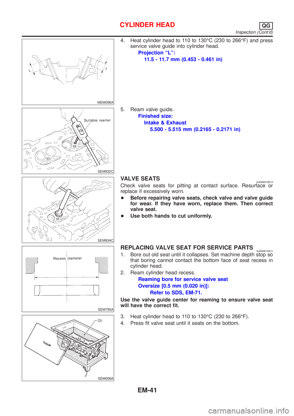
4. Heat cylinder head to 110 to 130ÉC (230 to 266ÉF) and press
service valve guide into cylinder head.
Projection ªLº:
11.5 - 11.7 mm (0.453 - 0.461 in)
SEM932C
5. Ream valve guide.
Finished size:
Intake & Exhaust
5.500 - 5.515 mm (0.2165 - 0.2171 in)
SEM934C
VALVE SEATSNJEM0019S10Check valve seats for pitting at contact surface. Resurface or
replace if excessively worn.
+Before repairing valve seats, check valve and valve guide
for wear. If they have worn, replace them. Then correct
valve seat.
+Use both hands to cut uniformly.
SEM795A
REPLACING VALVE SEAT FOR SERVICE PARTSNJEM0019S111. Bore out old seat until it collapses. Set machine depth stop so
that boring cannot contact the bottom face of seat recess in
cylinder head.
2. Ream cylinder head recess.
Reaming bore for service valve seat
Oversize [0.5 mm (0.020 in)]:
Refer to SDS, EM-71.
Use the valve guide center for reaming to ensure valve seat
will have the correct fit.
SEM008A
3. Heat cylinder head to 110 to 130ÉC (230 to 266ÉF).
4. Press fit valve seat until it seats on the bottom.
CYLINDER HEADQG
Inspection (Cont'd)
EM-41