Page 2225 of 2898
JEM116G
13. For Europe only, remove catalyst rear diffuser, EM-110, ªCata-
lystº.
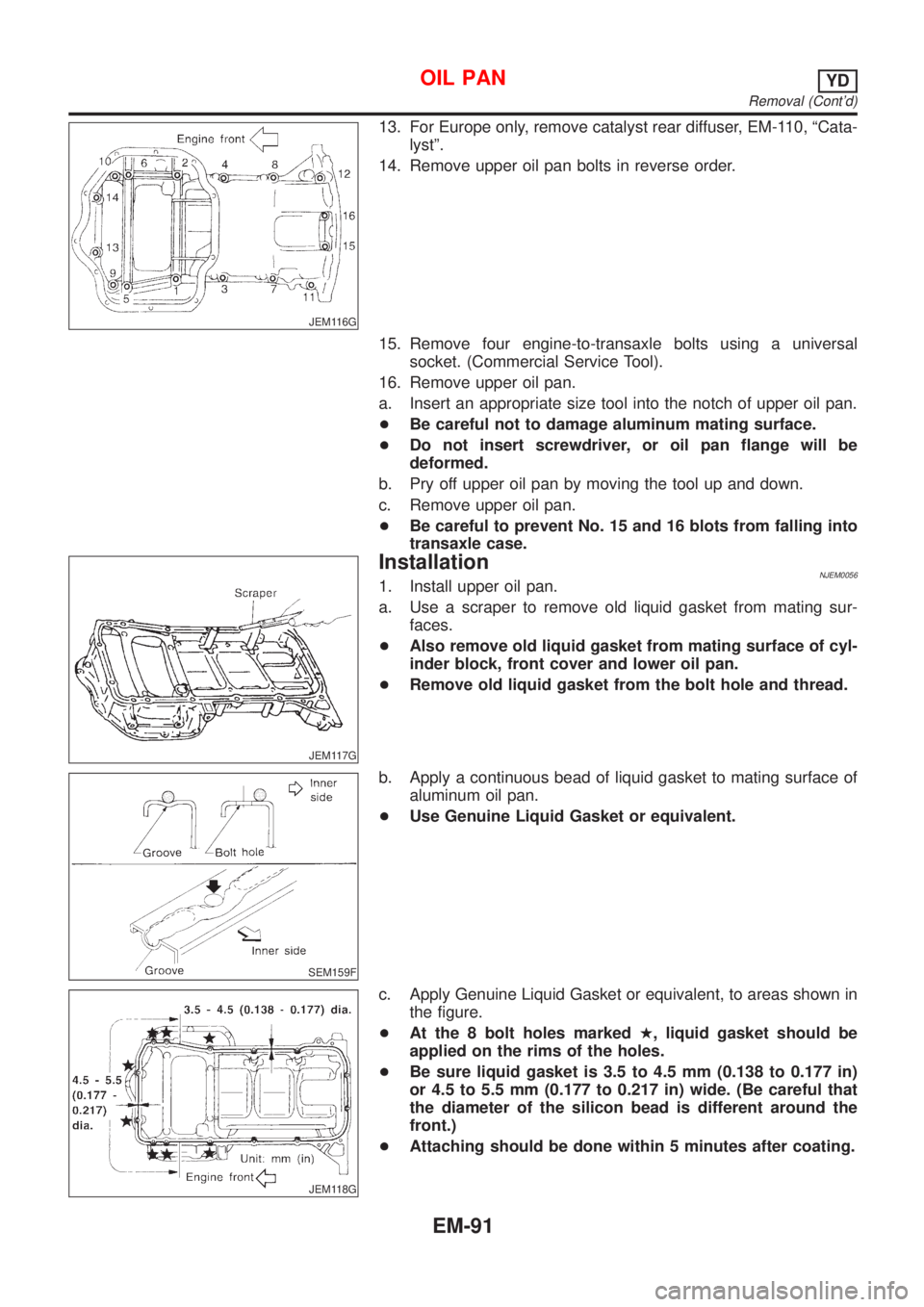
14. Remove upper oil pan bolts in reverse order.
15. Remove four engine-to-transaxle bolts using a universal
socket. (Commercial Service Tool).
16. Remove upper oil pan.
a. Insert an appropriate size tool into the notch of upper oil pan.
+Be careful not to damage aluminum mating surface.
+Do not insert screwdriver, or oil pan flange will be
deformed.
b. Pry off upper oil pan by moving the tool up and down.
c. Remove upper oil pan.
+Be careful to prevent No. 15 and 16 blots from falling into
transaxle case.
JEM117G
InstallationNJEM00561. Install upper oil pan.
a. Use a scraper to remove old liquid gasket from mating sur-
faces.
+Also remove old liquid gasket from mating surface of cyl-
inder block, front cover and lower oil pan.
+Remove old liquid gasket from the bolt hole and thread.
SEM159F
b. Apply a continuous bead of liquid gasket to mating surface of
aluminum oil pan.
+Use Genuine Liquid Gasket or equivalent.
JEM118G
c. Apply Genuine Liquid Gasket or equivalent, to areas shown in
the figure.
+At the 8 bolt holes markedH, liquid gasket should be
applied on the rims of the holes.
+Be sure liquid gasket is 3.5 to 4.5 mm (0.138 to 0.177 in)
or 4.5 to 5.5 mm (0.177 to 0.217 in) wide. (Be careful that
the diameter of the silicon bead is different around the
front.)
+Attaching should be done within 5 minutes after coating.
OIL PANYD
Removal (Cont'd)
EM-91
Page 2259 of 2898
SEM008A
VALVE GUIDE REPLACEMENTNJEM0065S09+When a valve guide is removed, replace with an oversized [0.2
mm (0.008 in)] valve guide.
1. To remove valve guide, heat cylinder head to 110 to 130ÉC
(230 to 266ÉF) by soaking in heated oil.
SEM931C
2. Drive out valve guide with a press [under a 20 kN (2 ton, 2.2
US ton, 2.0 Imp ton) pressure] or hammer and suitable tool.
SEM932C
3. Ream cylinder head valve guide hole.
Valve guide hole diameter (for service parts):
10.175 - 10.196 mm (0.4006 - 0.4014 in)
JEM156G
4. Heat cylinder head to 110 to 130ÉC (230 to 266ÉF) and press
service valve guide onto cylinder head.
Projection ªLº:
10.4 - 10.6 mm (0.409 - 0.417 in)
5. Ream valve guide.
Finished size:
6.000 - 6.018 mm (0.2362 - 0.2369 in)
CYLINDER HEADYD
Inspection (Cont'd)
EM-125
Page 2260 of 2898
SEM934C
JEM157G
VALVE SEATSNJEM0065S10+Before starting this check, confirm that the dimensions of valve
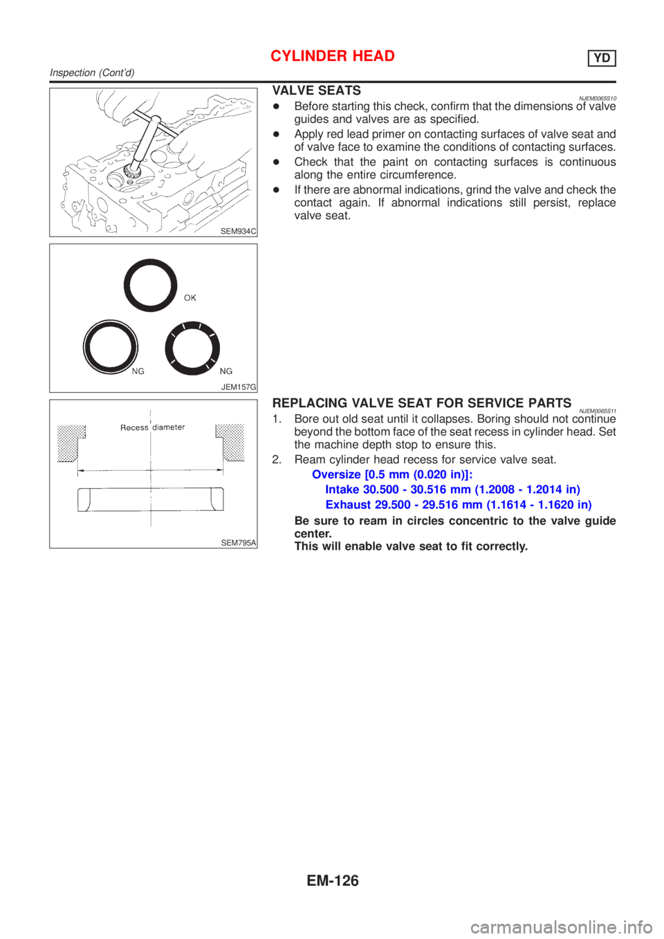
guides and valves are as specified.
+Apply red lead primer on contacting surfaces of valve seat and
of valve face to examine the conditions of contacting surfaces.
+Check that the paint on contacting surfaces is continuous
along the entire circumference.
+If there are abnormal indications, grind the valve and check the
contact again. If abnormal indications still persist, replace
valve seat.
SEM795A
REPLACING VALVE SEAT FOR SERVICE PARTSNJEM0065S111. Bore out old seat until it collapses. Boring should not continue
beyond the bottom face of the seat recess in cylinder head. Set
the machine depth stop to ensure this.
2. Ream cylinder head recess for service valve seat.
Oversize [0.5 mm (0.020 in)]:
Intake 30.500 - 30.516 mm (1.2008 - 1.2014 in)
Exhaust 29.500 - 29.516 mm (1.1614 - 1.1620 in)
Be sure to ream in circles concentric to the valve guide
center.
This will enable valve seat to fit correctly.
CYLINDER HEADYD
Inspection (Cont'd)
EM-126
Page 2272 of 2898
crankshaft position sensor (TDC sensor) from the assem-
bly.
+Always pay extra attention not to damage edge of crank-
shaft position sensor (TDC sensor) or ring gear teeth.
REMOVALNJEM0069S011. Remove engine undercover, and hood for hoisting.
2. Drain coolant from both cylinder block and radiator. Refer to
LC-44, ªChanging Engine Coolantº.
3. Remove the following parts:
+Battery
+RH and LH front wheels
+RH and LH splash covers (combined with undercover)
+Auxiliary belts
+Alternator
+Alternator brackets
+Radiator and cooling fan
+Engine cover
+Air ducts and air cleaner case
LH side of engine room:
4. Disconnect all harnesses and grounds that are connected to
components on vehicle.
5. Disconnect vacuum hose on vacuum pump side.
6. Disconnect fuel feed and fuel return hoses on engine side.
+Immediately put blind plugs into the openings to prevent
fuel from flowing out.
7. Disconnect heater hose. Plug opening of hose to prevent cool-
ant from flowing out.
RH side of engine room:
8. Remove air conditioner compressor from brackets and move
it toward vehicle side. Secure compressor on vehicle side with
rope.
Vehicle underside:
9. Remove exhaust front tube.
10. Disconnect two hoses from power steering pump and plug to
stop fluid.
11. Remove M/T control rod and support rod.
12. Remove ABS wheel sensor, and temporarily hang brake cali-
per with rope on vehicle side.
13. Remove RH and LH drive shafts.
SEM666G
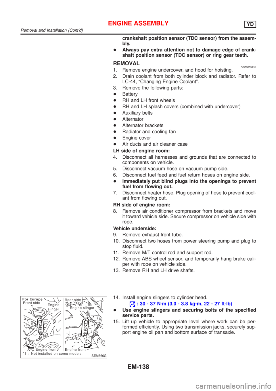
14. Install engine slingers to cylinder head.
: 30 - 37 N´m (3.0 - 3.8 kg-m, 22 - 27 ft-lb)
+Use engine slingers and securing bolts of the specified
service parts.
15. Lift up vehicle to appropriate level where work can be per-
formed efficiently. Using two transmission jacks, securely sup-
port engine oil pan and bottom surface of transaxle.
ENGINE ASSEMBLYYD
Removal and Installation (Cont'd)
EM-138
Page 2275 of 2898
Removal and InstallationNJEM0071CAUTION:
+When installing bearings, pistons, or other sliding parts,
lubricate contacting surfaces with new engine oil.
+Place removed parts such as bearings and bearing caps
in their proper order and direction.
+When installing connecting rod nuts, and main bearing
cap bolts, apply new engine oil to threads and seating
surfaces.
+Do not allow any magnetic materials to contact the signal
plate of flywheel.
+Do not remove the signal plate at back.
+Do not place the signal plate side facing under.
+Handle with care so as not to damage the signal plate
[especially four places on protrusions for signal of crank
position sensor (TDC sensor)].
DisassemblyNJEM0072PISTON AND CRANKSHAFTNJEM0072S011. Remove engine. Refer to ªENGINE ASSEMBLYº, ªRemoval
and Installationº, EM-137.
2. Place engine on a work stand.
a. Remove flywheel.
+Hold ring gear with ring gear stopper (KV10105630,
KV10105610). Then, loosen securing bolts with TORX socket
(size: Q8 E20, Commercial Service Tool) and remove them.
As an alternative method, hold the crankshaft pulley with a
pulley holder (SST) to remove the flywheel.
JEM192G
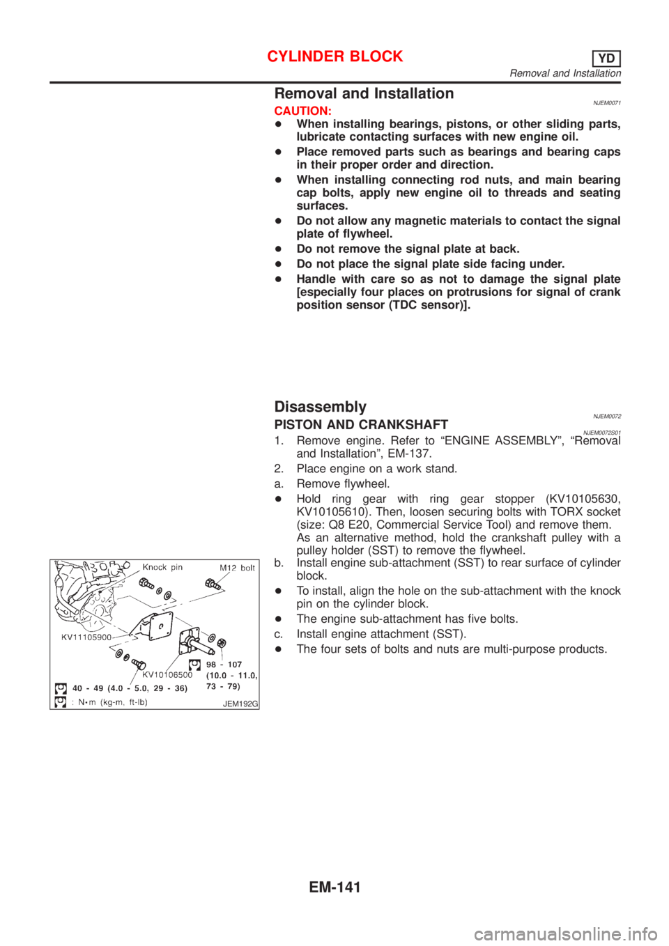
b. Install engine sub-attachment (SST) to rear surface of cylinder
block.
+To install, align the hole on the sub-attachment with the knock
pin on the cylinder block.
+The engine sub-attachment has five bolts.
c. Install engine attachment (SST).
+The four sets of bolts and nuts are multi-purpose products.
CYLINDER BLOCKYD
Removal and Installation
EM-141
Page 2277 of 2898
+Store the removed parts in sets by the cylinder No. to avoid
mixing them up.
JEM196G
11. Remove piston rings from pistons.
+Use piston ring expander (Commercial Service Tool).
+Avoid scratching pistons during removal.
+Be careful not to damage piston rings by expanding
excessively.
CAUTION:
+When piston rings are not replaced, make sure that piston
rings are mounted in their original positions.
JEM197G
12. Remove piston from connecting rod.
a. Remove snap rings using snap ring pliers.
JEM198G
b. With an industrial drier, heat pistons to 60 to 70ÉC (140 to
158ÉF).
JEM199G
c. Push out piston pin with a rod approx. 26 mm (1.02 in) in
diameter.
CYLINDER BLOCKYD
Disassembly (Cont'd)
EM-143
Page 2278 of 2898
JEM200G
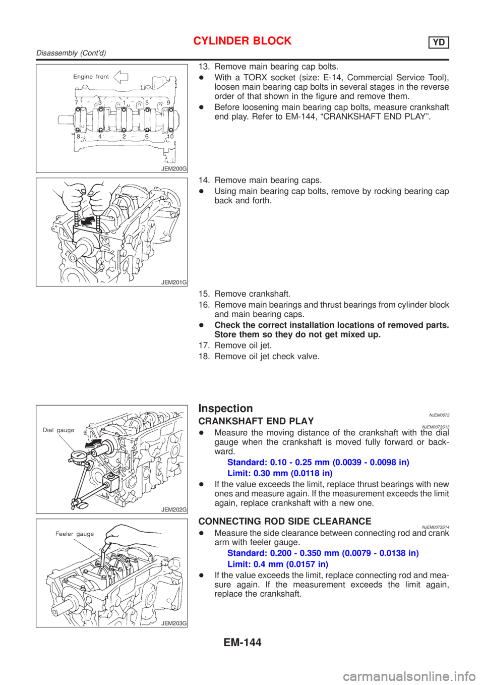
13. Remove main bearing cap bolts.
+With a TORX socket (size: E-14, Commercial Service Tool),
loosen main bearing cap bolts in several stages in the reverse
order of that shown in the figure and remove them.
+Before loosening main bearing cap bolts, measure crankshaft
end play. Refer to EM-144, ªCRANKSHAFT END PLAYº.
JEM201G
14. Remove main bearing caps.
+Using main bearing cap bolts, remove by rocking bearing cap
back and forth.
15. Remove crankshaft.
16. Remove main bearings and thrust bearings from cylinder block
and main bearing caps.
+Check the correct installation locations of removed parts.
Store them so they do not get mixed up.
17. Remove oil jet.
18. Remove oil jet check valve.
JEM202G
InspectionNJEM0073CRANKSHAFT END PLAYNJEM0073S13+Measure the moving distance of the crankshaft with the dial
gauge when the crankshaft is moved fully forward or back-
ward.
Standard: 0.10 - 0.25 mm (0.0039 - 0.0098 in)
Limit: 0.30 mm (0.0118 in)
+If the value exceeds the limit, replace thrust bearings with new
ones and measure again. If the measurement exceeds the limit
again, replace crankshaft with a new one.
JEM203G
CONNECTING ROD SIDE CLEARANCENJEM0073S14+Measure the side clearance between connecting rod and crank
arm with feeler gauge.
Standard: 0.200 - 0.350 mm (0.0079 - 0.0138 in)
Limit: 0.4 mm (0.0157 in)
+If the value exceeds the limit, replace connecting rod and mea-
sure again. If the measurement exceeds the limit again,
replace the crankshaft.
CYLINDER BLOCKYD
Disassembly (Cont'd)
EM-144
Page 2282 of 2898
SEM509G
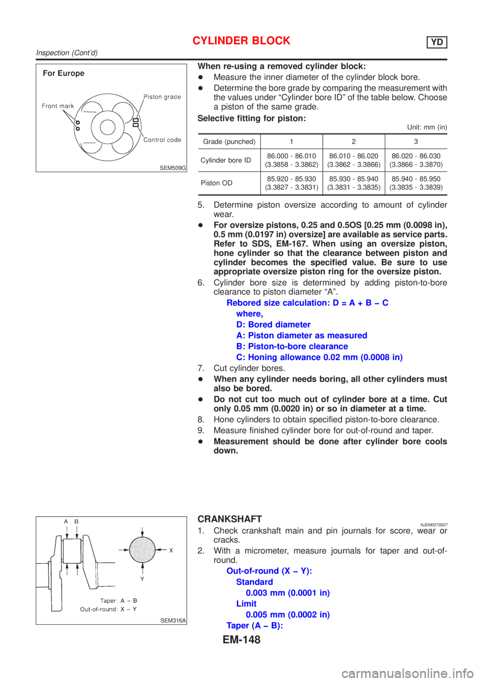
When re-using a removed cylinder block:
+Measure the inner diameter of the cylinder block bore.
+Determine the bore grade by comparing the measurement with
the values under ªCylinder bore IDº of the table below. Choose
a piston of the same grade.
Selective fitting for piston:
Unit: mm (in)
Grade (punched) 1 2 3
Cylinder bore ID86.000 - 86.010
(3.3858 - 3.3862)86.010 - 86.020
(3.3862 - 3.3866)86.020 - 86.030
(3.3866 - 3.3870)
Piston OD85.920 - 85.930
(3.3827 - 3.3831)85.930 - 85.940
(3.3831 - 3.3835)85.940 - 85.950
(3.3835 - 3.3839)
5. Determine piston oversize according to amount of cylinder
wear.
+For oversize pistons, 0.25 and 0.5OS [0.25 mm (0.0098 in),
0.5 mm (0.0197 in) oversize] are available as service parts.
Refer to SDS, EM-167. When using an oversize piston,
hone cylinder so that the clearance between piston and
cylinder becomes the specified value. Be sure to use
appropriate oversize piston ring for the oversize piston.
6. Cylinder bore size is determined by adding piston-to-bore
clearance to piston diameter ªAº.
Rebored size calculation: D = A+BþC
where,
D: Bored diameter
A: Piston diameter as measured
B: Piston-to-bore clearance
C: Honing allowance 0.02 mm (0.0008 in)
7. Cut cylinder bores.
+When any cylinder needs boring, all other cylinders must
also be bored.
+Do not cut too much out of cylinder bore at a time. Cut
only 0.05 mm (0.0020 in) or so in diameter at a time.
8. Hone cylinders to obtain specified piston-to-bore clearance.
9. Measure finished cylinder bore for out-of-round and taper.
+Measurement should be done after cylinder bore cools
down.
SEM316A
CRANKSHAFTNJEM0073S071. Check crankshaft main and pin journals for score, wear or
cracks.
2. With a micrometer, measure journals for taper and out-of-
round.
Out-of-round (X þ Y):
Standard
0.003 mm (0.0001 in)
Limit
0.005 mm (0.0002 in)
Taper (A þ B):
CYLINDER BLOCKYD
Inspection (Cont'd)
EM-148