2001 NISSAN ALMERA service
[x] Cancel search: servicePage 2040 of 2898
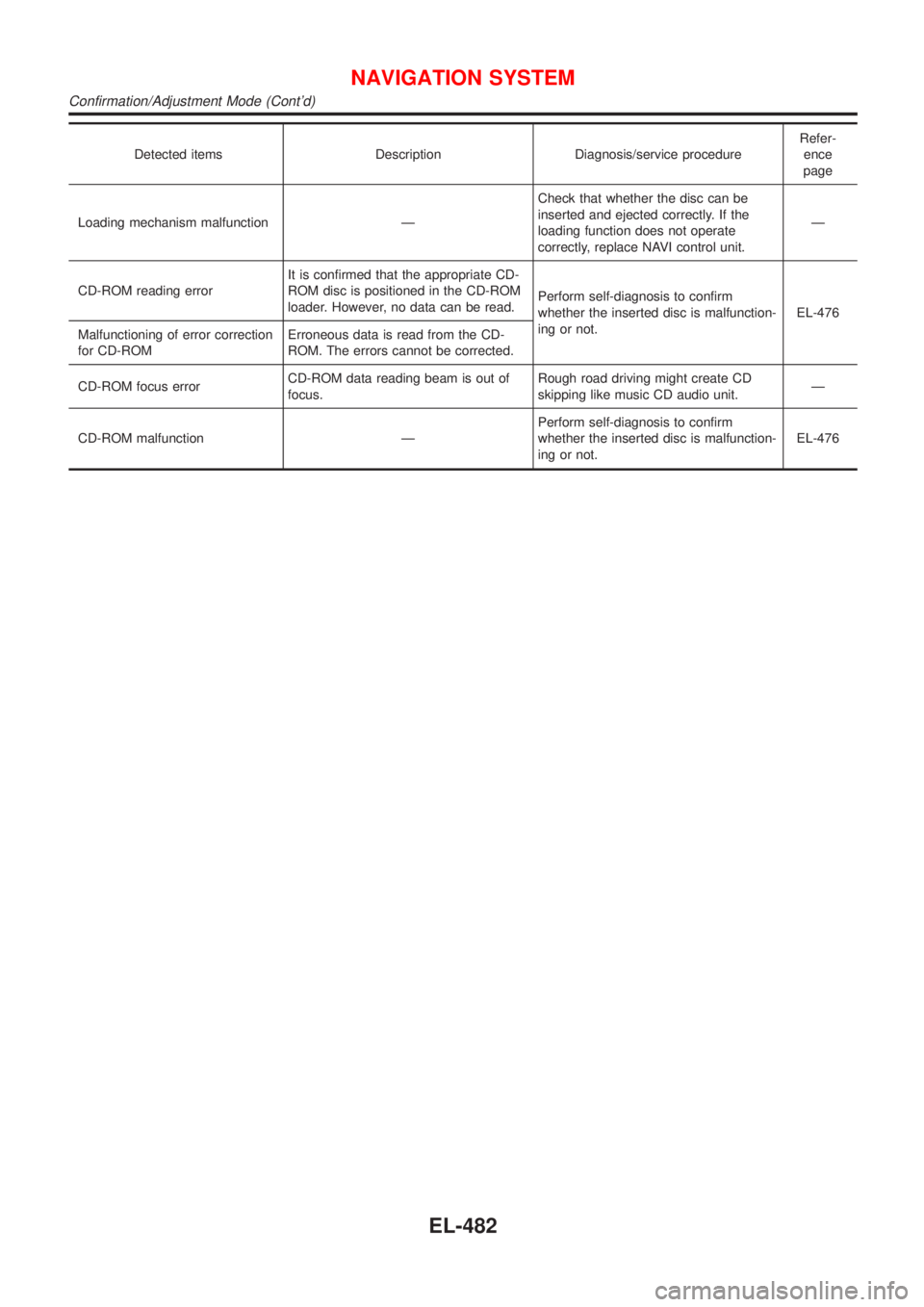
Detected items Description Diagnosis/service procedureRefer-
ence
page
Loading mechanism malfunction ÐCheck that whether the disc can be
inserted and ejected correctly. If the
loading function does not operate
correctly, replace NAVI control unit.Ð
CD-ROM reading errorIt is confirmed that the appropriate CD-
ROM disc is positioned in the CD-ROM
loader. However, no data can be read.Perform self-diagnosis to confirm
whether the inserted disc is malfunction-
ing or not.EL-476
Malfunctioning of error correction
for CD-ROMErroneous data is read from the CD-
ROM. The errors cannot be corrected.
CD-ROM focus errorCD-ROM data reading beam is out of
focus.Rough road driving might create CD
skipping like music CD audio unit.Ð
CD-ROM malfunction ÐPerform self-diagnosis to confirm
whether the inserted disc is malfunction-
ing or not.EL-476
NAVIGATION SYSTEM
Confirmation/Adjustment Mode (Cont'd)
EL-482
Page 2058 of 2898
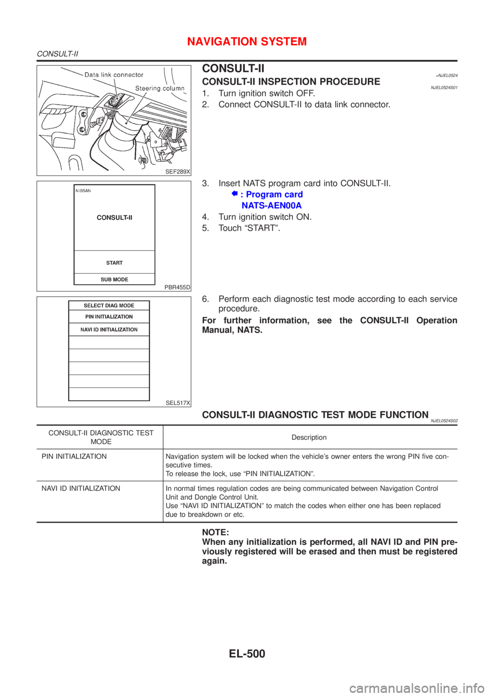
SEF289X
CONSULT-II=NJEL0524CONSULT-II INSPECTION PROCEDURENJEL0524S011. Turn ignition switch OFF.
2. Connect CONSULT-II to data link connector.
PBR455D
3. Insert NATS program card into CONSULT-II.
: Program card
NATS-AEN00A
4. Turn ignition switch ON.
5. Touch ªSTARTº.
SEL517X
6. Perform each diagnostic test mode according to each service
procedure.
For further information, see the CONSULT-II Operation
Manual, NATS.
CONSULT-II DIAGNOSTIC TEST MODE FUNCTIONNJEL0524S02
CONSULT-II DIAGNOSTIC TEST
MODEDescription
PIN INITIALIZATION Navigation system will be locked when the vehicle's owner enters the wrong PIN five con-
secutive times.
To release the lock, use ªPIN INITIALIZATIONº.
NAVI ID INITIALIZATION In normal times regulation codes are being communicated between Navigation Control
Unit and Dongle Control Unit.
Use ªNAVI ID INITIALIZATIONº to match the codes when either one has been replaced
due to breakdown or etc.
NOTE:
When any initialization is performed, all NAVI ID and PIN pre-
viously registered will be erased and then must be registered
again.
NAVIGATION SYSTEM
CONSULT-II
EL-500
Page 2059 of 2898
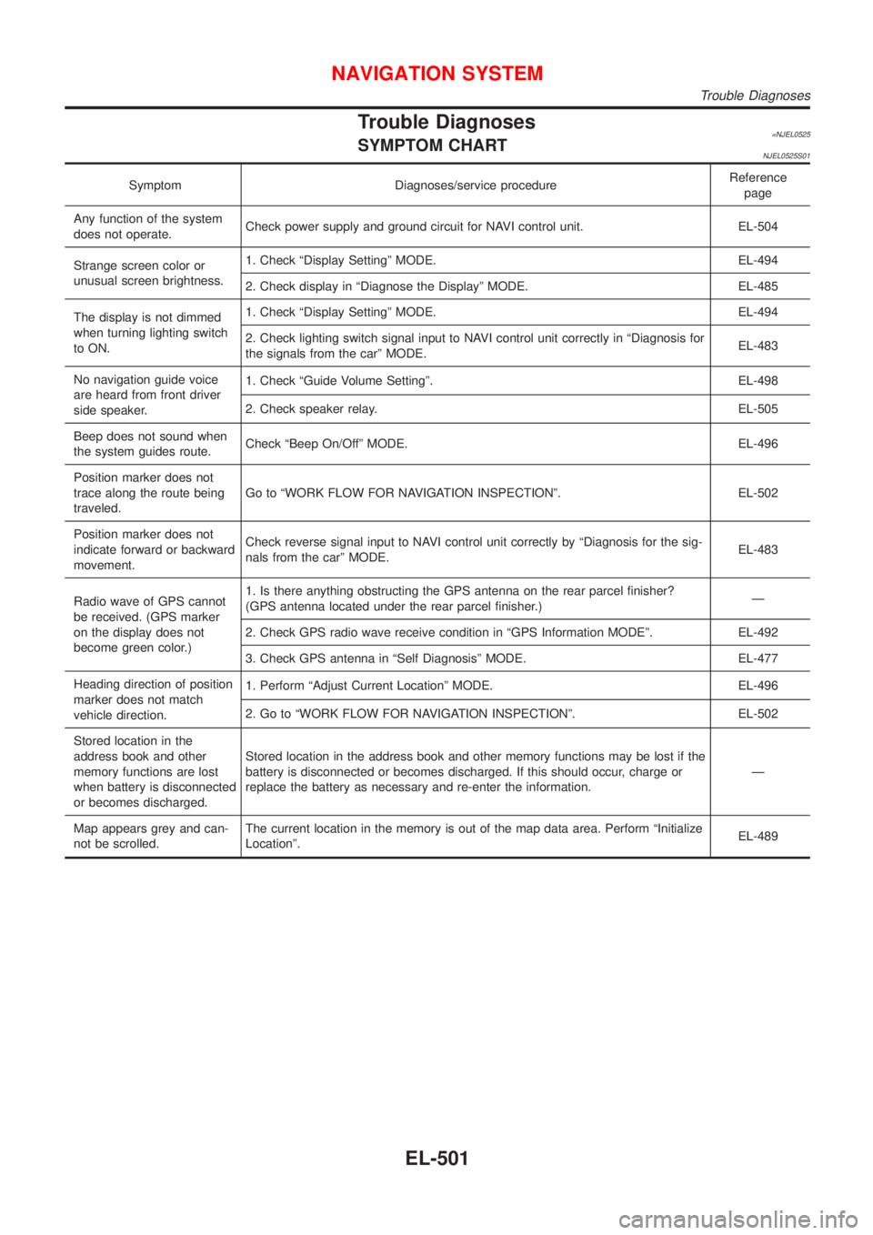
Trouble Diagnoses=NJEL0525SYMPTOM CHARTNJEL0525S01
Symptom Diagnoses/service procedureReference
page
Any function of the system
does not operate.Check power supply and ground circuit for NAVI control unit. EL-504
Strange screen color or
unusual screen brightness.1. Check ªDisplay Settingº MODE. EL-494
2. Check display in ªDiagnose the Displayº MODE. EL-485
The display is not dimmed
when turning lighting switch
to ON.1. Check ªDisplay Settingº MODE. EL-494
2. Check lighting switch signal input to NAVI control unit correctly in ªDiagnosis for
the signals from the carº MODE.EL-483
No navigation guide voice
are heard from front driver
side speaker.1. Check ªGuide Volume Settingº. EL-498
2. Check speaker relay. EL-505
Beep does not sound when
the system guides route.Check ªBeep On/Offº MODE. EL-496
Position marker does not
trace along the route being
traveled.Go to ªWORK FLOW FOR NAVIGATION INSPECTIONº. EL-502
Position marker does not
indicate forward or backward
movement.Check reverse signal input to NAVI control unit correctly by ªDiagnosis for the sig-
nals from the carº MODE.EL-483
Radio wave of GPS cannot
be received. (GPS marker
on the display does not
become green color.)1. Is there anything obstructing the GPS antenna on the rear parcel finisher?
(GPS antenna located under the rear parcel finisher.)Ð
2. Check GPS radio wave receive condition in ªGPS Information MODEº. EL-492
3. Check GPS antenna in ªSelf Diagnosisº MODE. EL-477
Heading direction of position
marker does not match
vehicle direction.1. Perform ªAdjust Current Locationº MODE. EL-496
2. Go to ªWORK FLOW FOR NAVIGATION INSPECTIONº. EL-502
Stored location in the
address book and other
memory functions are lost
when battery is disconnected
or becomes discharged.Stored location in the address book and other memory functions may be lost if the
battery is disconnected or becomes discharged. If this should occur, charge or
replace the battery as necessary and re-enter the information.Ð
Map appears grey and can-
not be scrolled.The current location in the memory is out of the map data area. Perform ªInitialize
Locationº.EL-489
NAVIGATION SYSTEM
Trouble Diagnoses
EL-501
Page 2067 of 2898
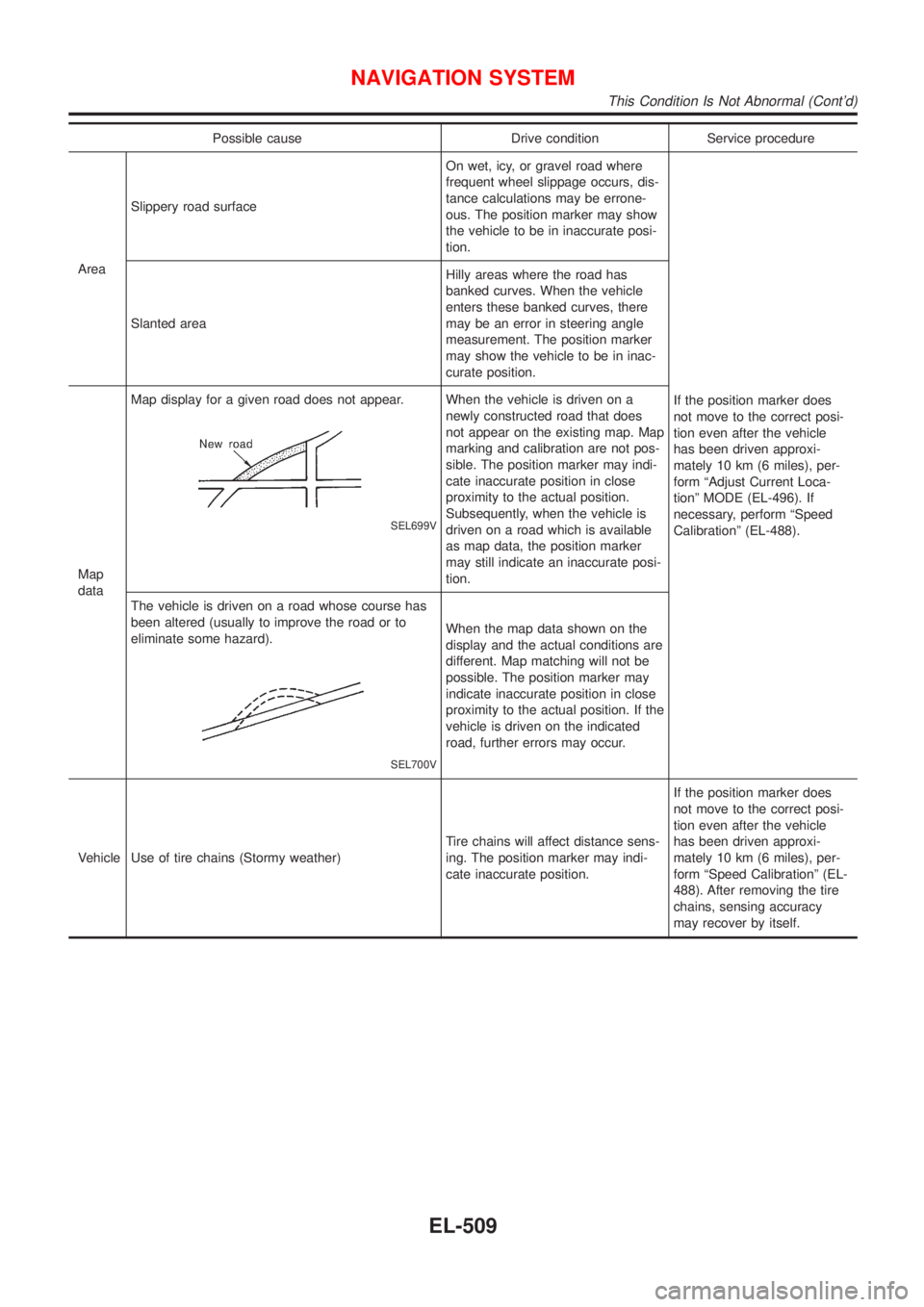
Possible cause Drive condition Service procedure
AreaSlippery road surfaceOn wet, icy, or gravel road where
frequent wheel slippage occurs, dis-
tance calculations may be errone-
ous. The position marker may show
the vehicle to be in inaccurate posi-
tion.
If the position marker does
not move to the correct posi-
tion even after the vehicle
has been driven approxi-
mately 10 km (6 miles), per-
form ªAdjust Current Loca-
tionº MODE (EL-496). If
necessary, perform ªSpeed
Calibrationº (EL-488). Slanted areaHilly areas where the road has
banked curves. When the vehicle
enters these banked curves, there
may be an error in steering angle
measurement. The position marker
may show the vehicle to be in inac-
curate position.
Map
dataMap display for a given road does not appear.
SEL699V
When the vehicle is driven on a
newly constructed road that does
not appear on the existing map. Map
marking and calibration are not pos-
sible. The position marker may indi-
cate inaccurate position in close
proximity to the actual position.
Subsequently, when the vehicle is
driven on a road which is available
as map data, the position marker
may still indicate an inaccurate posi-
tion.
The vehicle is driven on a road whose course has
been altered (usually to improve the road or to
eliminate some hazard).
SEL700V
When the map data shown on the
display and the actual conditions are
different. Map matching will not be
possible. The position marker may
indicate inaccurate position in close
proximity to the actual position. If the
vehicle is driven on the indicated
road, further errors may occur.
Vehicle Use of tire chains (Stormy weather)Tire chains will affect distance sens-
ing. The position marker may indi-
cate inaccurate position.If the position marker does
not move to the correct posi-
tion even after the vehicle
has been driven approxi-
mately 10 km (6 miles), per-
form ªSpeed Calibrationº (EL-
488). After removing the tire
chains, sensing accuracy
may recover by itself.
NAVIGATION SYSTEM
This Condition Is Not Abnormal (Cont'd)
EL-509
Page 2068 of 2898
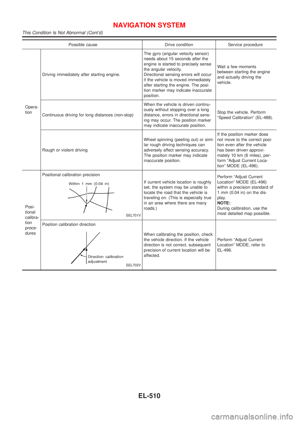
Possible cause Drive condition Service procedure
Opera-
tionDriving immediately after starting engine.The gyro (angular velocity sensor)
needs about 15 seconds after the
engine is started to precisely sense
the angular velocity.
Directional sensing errors will occur
if the vehicle is moved immediately
after starting the engine. The posi-
tion marker may indicate inaccurate
position.Wait a few moments
between starting the engine
and actually driving the
vehicle.
Continuous driving for long distances (non-stop)When the vehicle is driven continu-
ously without stopping over a long
distance, errors in directional sens-
ing may occur. The position marker
may indicate inaccurate position.Stop the vehicle. Perform
ªSpeed Calibrationº (EL-488).
Rough or violent drivingWheel spinning (peeling out) or simi-
lar rough driving techniques can
adversely affect sensing accuracy.
The position marker may indicate
inaccurate position.If the position marker does
not move to the correct posi-
tion even after the vehicle
has been driven approxi-
mately 10 km (6 miles), per-
form ªAdjust Current Loca-
tionº MODE (EL-496).
Posi-
tional
calibra-
tion
proce-
duresPositional calibration precision
SEL701V
If current vehicle location is roughly
set, the system may be unable to
locate the road that the vehicle is
traveling on. (This is especially true
in an area where there are many
roads.)Perform ªAdjust Current
Locationº MODE (EL-496)
within a precision standard of
1 mm (0.04 in) on the dis-
play.
NOTE:
During calibration, use the
most detailed map possible.
Position calibration direction
SEL702V
When calibrating the position, check
the vehicle direction. If the vehicle
direction is not correct, subsequent
precision of current location will be
affected.Perform ªAdjust Current
Locationº MODE, refer to
EL-496.
NAVIGATION SYSTEM
This Condition Is Not Abnormal (Cont'd)
EL-510
Page 2069 of 2898
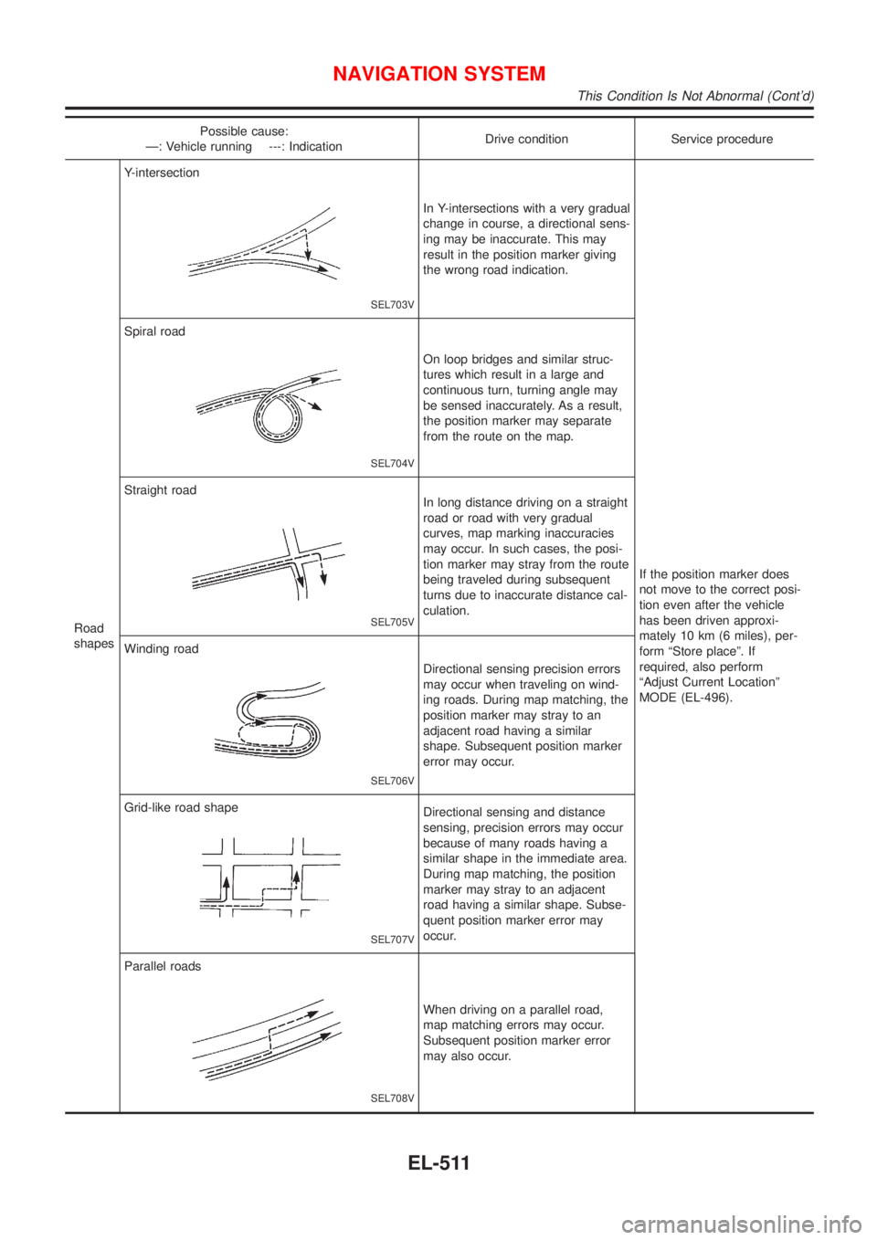
Possible cause:
Ð: Vehicle running ---: IndicationDrive condition Service procedure
Road
shapesY-intersection
SEL703V
In Y-intersections with a very gradual
change in course, a directional sens-
ing may be inaccurate. This may
result in the position marker giving
the wrong road indication.
If the position marker does
not move to the correct posi-
tion even after the vehicle
has been driven approxi-
mately 10 km (6 miles), per-
form ªStore placeº. If
required, also perform
ªAdjust Current Locationº
MODE (EL-496). Spiral road
SEL704V
On loop bridges and similar struc-
tures which result in a large and
continuous turn, turning angle may
be sensed inaccurately. As a result,
the position marker may separate
from the route on the map.
Straight road
SEL705V
In long distance driving on a straight
road or road with very gradual
curves, map marking inaccuracies
may occur. In such cases, the posi-
tion marker may stray from the route
being traveled during subsequent
turns due to inaccurate distance cal-
culation.
Winding road
SEL706V
Directional sensing precision errors
may occur when traveling on wind-
ing roads. During map matching, the
position marker may stray to an
adjacent road having a similar
shape. Subsequent position marker
error may occur.
Grid-like road shape
SEL707V
Directional sensing and distance
sensing, precision errors may occur
because of many roads having a
similar shape in the immediate area.
During map matching, the position
marker may stray to an adjacent
road having a similar shape. Subse-
quent position marker error may
occur.
Parallel roads
SEL708V
When driving on a parallel road,
map matching errors may occur.
Subsequent position marker error
may also occur.
NAVIGATION SYSTEM
This Condition Is Not Abnormal (Cont'd)
EL-511
Page 2070 of 2898
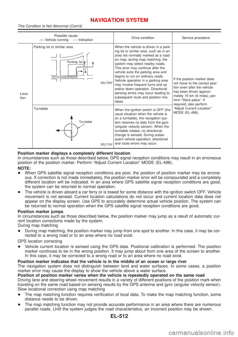
Possible cause:
Ð: Vehicle running ---: IndicationDrive condition Service procedure
Loca-
tionParking lot or similar area
SEL709V
When the vehicle is driven in a park-
ing lot or similar area, such as in an
area not normally marked as a road
on map, during map matching, the
system may select nearby roads.
This error may continue after the
vehicle exits the parking area and
begins to run on ordinary roads.
Vehicle operation in a parking area
may involve frequent turns and up
and/or down operation. Directional
sensing errors may occur leading to
subsequent route and position mis-
takes.If the position marker does
not move to the correct posi-
tion even after the vehicle
has been driven approxi-
mately 10 km (6 miles), per-
form ªStore placeº. If
required, also perform
ªAdjust Current Locationº
MODE (EL-496). Turntable
SEL710V
When the ignition switch is OFF (the
usual situation when the vehicle is
on a turntable), the navigation sys-
tem receives no data from the gyro
(angular velocity sensor). When the
turntable rotates, no directional
change is sensed. During subse-
quent vehicle operation, directional
and route errors may occur.
Position marker displays a completely different location
In circumstances such as those described below, GPS signal reception conditions may result in an erroneous
position of the position marker. Perform ªAdjust Current Locationº MODE (EL-496).
NOTE:
+When GPS satellite signal reception conditions are poor, the position of position marker may be errone-
ous. If correction is not made immediately, the position marker error will be compounded and a completely
different location will be indicated. In an area where GPS satellite signal reception conditions are good,
the system can be returned to normal operation.
+The vehicle is driven aboard a car ferry or is towed for some distance with the ignition switch OFF. Vehicle
movement is not sensed. Current location calculations do not occur and current location data does not
appear on the display screen. Use GPS to accurately determine actual vehicle position. The system can
be returned to normal operation when the GPS satellite signal reception conditions are good.
Position marker jumps
In circumstances such as those described below, the position marker may jump as a result of automatic cur-
rent location corrections made by the system.
During map matching
+During map matching, the position marker may jump from one spot to another. In this case, it may be cor-
rected to a wrong road or to an area where no road exist.
GPS location correcting
+Vehicle current location is sensed using the GPS data. Positional calibration is performed. The position
marker continues to be in the wrong position. It may jump about from one area of the screen to another.
In this case, it may be corrected to a wrong road or to an area where no road exist.
Position marker indicates that the vehicle is in the middle of an ocean or large river
The navigation system does not distinguish between land and water surfaces. In some cases, a position
marker error may cause the display to show the vehicle above a water surface.
Position of position marker varies when the vehicle is repeatedly operated on the same road
Driving lane and steering wheel movement results in a variety of different positions of the position mark when
traveling on the same road based on sensing results by the GPS antenna and gyro (angular velocity sensor).
Slow locational correction using map matching
+The map matching function requires verification of local data. To make the map matching function, some
distance needs to be driven.
+The map matching function may not provide accurate performance in an area where there are numerous
parallel roads. Until the system judges the road characteristics, an incorrect position may be shown.
NAVIGATION SYSTEM
This Condition Is Not Abnormal (Cont'd)
EL-512
Page 2135 of 2898
ENGINE MECHANICAL
SECTION
EM
CONTENTS
QG
PRECAUTIONS...............................................................4
Parts Requiring Angular Tightening .............................4
Liquid Gasket Application Procedure ..........................4
PREPARATION...............................................................5
Special Service Tools ..................................................5
Commercial Service Tools ...........................................7
NOISE, VIBRATION AND HARSHNESS (NVH)
TROUBLESHOOTING.....................................................9
NVH Troubleshooting - Engine Noise .........................9
OUTER COMPONENT PARTS..................................... 11
Removal and Installation ........................................... 11
MEASUREMENT OF COMPRESSION PRESSURE....15
DRIVE BELTS................................................................16
Checking ....................................................................16
AIR CLEANER...............................................................18
Cleaning and Changing .............................................18
VISCOUS PAPER TYPE...........................................18
DRY PAPER TYPE..................................................18
SPARK PLUG................................................................19
Checking and Changing ............................................19
OIL PAN.........................................................................20
Components...............................................................20
Removal .....................................................................20
Installation ..................................................................21
TIMING CHAIN..............................................................23
Components...............................................................23
Removal .....................................................................24
Inspection...................................................................27
Installation ..................................................................28
OIL SEAL.......................................................................32
Replacement ..............................................................32
VALVE OIL SEAL.....................................................32
FRONT OIL SEAL....................................................32
REAR OIL SEAL......................................................33
CYLINDER HEAD..........................................................34
Components...............................................................34
Removal .....................................................................35
Disassembly...............................................................37Inspection...................................................................37
CYLINDER HEAD DISTORTION...............................37
CAMSHAFT VISUAL CHECK....................................37
CAMSHAFT RUNOUT..............................................38
CAMSHAFT CAM HEIGHT.......................................38
CAMSHAFT JOURNAL CLEARANCE........................38
CAMSHAFT END PLAY............................................39
CAMSHAFT SPROCKET RUNOUT...........................39
VALVE GUIDE CLEARANCE....................................39
VALVE GUIDE REPLACEMENT................................40
VALVE SEATS.........................................................41
REPLACING VALVE SEAT FOR SERVICE PARTS....41
VALVE DIMENSIONS...............................................42
VALVE SPRING.......................................................42
VALVE LIFTER AND VALVE SHIM............................43
Valve Clearance.........................................................44
CHECKING.............................................................44
ADJUSTING............................................................45
Assembly ...................................................................46
Installation ..................................................................47
ENGINE ASSEMBLY.....................................................51
Removal and Installation ...........................................51
REMOVAL...............................................................52
INSTALLATION........................................................53
CYLINDER BLOCK.......................................................54
Components...............................................................54
Removal and Installation ...........................................55
Disassembly...............................................................55
PISTON AND CRANKSHAFT....................................55
Inspection...................................................................56
PISTON AND PISTON PIN CLEARANCE..................56
PISTON RING SIDE CLEARANCE............................56
PISTON RING END GAP..........................................56
CONNECTING ROD BEND AND TORSION...............57
CYLINDER BLOCK DISTORTION AND WEAR...........57
PISTON-TO-BORE CLEARANCE..............................58
CRANKSHAFT.........................................................59
BEARING CLEARANCE...........................................59
CONNECTING ROD BUSHING CLEARANCE
(SMALL END)
..........................................................61