2001 NISSAN ALMERA service
[x] Cancel search: servicePage 1816 of 2898
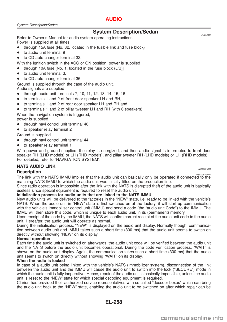
System Description/Sedan=NJEL0381Refer to Owner's Manual for audio system operating instructions.
Power is supplied at all times
+through 15A fuse (No. 32, located in the fusible link and fuse block)
+to audio unit terminal 9
+to CD auto changer terminal 32.
With the ignition switch in the ACC or ON position, power is supplied
+through 10A fuse [No. 1, located in the fuse block (J/B)]
+to audio unit terminal 3,
+to CD auto changer terminal 36
Ground is supplied through the case of the audio unit.
Audio signals are supplied
+through audio unit terminals 7, 10, 11, 12, 13, 14, 15, 16
+to terminals 1 and 2 of front door speaker LH and RH,
+to terminals 1 and 2 of rear door speaker LH and RH and
+to terminals 1 and 2 of pillar tweeter LH and RH (with 6 speakers)
When the navigation system is triggered,
power is supplied
+through navi control unit terminal 46
+to speaker relay terminal 2
Ground is supplied
+through navi control unit terminal 44
+to speaker relay terminal 1
With power and ground supplied, the relay is energized, and then audio signal is interrupted to front door
speaker RH (LHD models) or LH (RHD models), and pillar tweeter RH (LHD models) or LH (RHD models)
For detailed, refer to ªNAVIGATION SYSTEMº.
NATS AUDIO LINKNJEL0381S04DescriptionNJEL0381S0401The link with the NATS IMMU implies that the audio unit can basically only be operated if connected to the
matching NATS IMMU to which the audio unit was initially fitted on the production line.
Since radio operation is impossible after the link with the NATS is disrupted theft of the audio unit is basically
useless since special equipment is required to reset the audio unit.
Initialization process for audio units that are linked to the NATS IMMU
New audio units will be delivered to the factories in the ªNEWº state, i.e. ready to be linked with the vehicle's
NATS. When the audio unit in ªNEWº state is first switched on at the factory, it will start up communication
with the vehicle's immobiliser control unit (IMMU) and send a code (the ªaudio unit Codeº) to the IMMU. The
IMMU will then store this code, which is unique to each audio unit, in its (permanent) memory.
Upon receipt of the code by the IMMU, the NATS will confirm correct receipt of the audio unit code to the audio
unit. Hereafter, the audio unit will operate as normal.
During the initialisation process, ªNEWº is displayed on the audio unit display. Normally though, communica-
tion between audio unit and IMMU takes such a short time (300 ms) that the audio unit seems to switch on
directly without showing ªNEWº on its display.
Normal operation
Each time the audio unit is switched on afterwards, the audio unit code will be verified between the audio unit
and the NATS before the audio unit becomes operational. During the code verification process, ªWAITº is
shown on the audio unit display. Again, the communication takes such a short time (300 ms) that the audio
unit seems to switch on directly without showing ªWAITº on its display.
When the radio is locked
In case of a audio unit being linked with the vehicle's NATS (immobilizer system), disconnection of the link
between the audio unit and the IMMU will cause the audio unit to switch into the lock (ªSECUREº) mode in
which the audio unit is fully inoperative. Hence, repair of the audio unit is basically impossible, unless the audio
unit is reset to the ªNEWº state for which special decoding equipment is required.
Clarion has provided their authorized service representatives with so called ªdecoder boxesº which can bring
the audio unit back to the ªNEWº state, enabling the audio unit to be switched on after which repair can be
AUDIO
System Description/Sedan
EL-258
Page 1827 of 2898
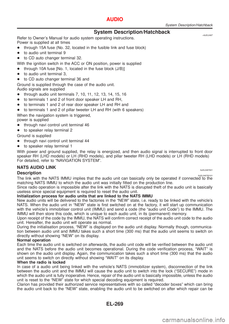
System Description/Hatchback=NJEL0497Refer to Owner's Manual for audio system operating instructions.
Power is supplied at all times
+through 15A fuse (No. 32, located in the fusible link and fuse block)
+to audio unit terminal 9
+to CD auto changer terminal 32.
With the ignition switch in the ACC or ON position, power is supplied
+through 10A fuse [No. 1, located in the fuse block (J/B)]
+to audio unit terminal 3,
+to CD auto changer terminal 36 and
Ground is supplied through the case of the audio unit.
Audio signals are supplied
+through audio unit terminals 7, 10, 11, 12, 13, 14, 15, 16
+to terminals 1 and 2 of front door speaker LH and RH,
+to terminals 1 and 2 of rear door speaker LH and RH and
+to terminals 1 and 2 of pillar tweeter LH and RH (with 6 speakers)
When the navigation system is triggered,
power is supplied
+through navi control unit terminal 46
+to speaker relay terminal 2
Ground is supplied
+through navi control unit terminal 44
+to speaker relay terminal 1
With power and ground supplied, the relay is energized, and then audio signal is interrupted to front door
speaker RH (LHD models) or LH (RHD models), and pillar tweeter RH (LHD models) or LH (RHD models)
For detailed, refer to ªNAVIGATION SYSTEMº.
NATS AUDIO LINKNJEL0497S01DescriptionNJEL0497S0101The link with the NATS IMMU implies that the audio unit can basically only be operated if connected to the
matching NATS IMMU to which the audio unit was initially fitted on the production line.
Since radio operation is impossible after the link with the NATS is disrupted theft of the audio unit is basically
useless since special equipment is required to reset the audio unit.
Initialization process for audio units that are linked to the NATS IMMU
New audio units will be delivered to the factories in the ªNEWº state, i.e. ready to be linked with the vehicle's
NATS. When the audio unit in ªNEWº state is first switched on at the factory, it will start up communication
with the vehicle's immobiliser control unit (IMMU) and send a code (the ªaudio unit Codeº) to the IMMU. The
IMMU will then store this code, which is unique to each audio unit, in its (permanent) memory.
Upon receipt of the code by the IMMU, the NATS will confirm correct receipt of the audio unit code to the audio
unit. Hereafter, the audio unit will operate as normal.
During the initialisation process, ªNEWº is displayed on the audio unit display. Normally though, communica-
tion between audio unit and IMMU takes such a short time (300 ms) that the audio unit seems to switch on
directly without showing ªNEWº on its display.
Normal operation
Each time the audio unit is switched on afterwards, the audio unit code will be verified between the audio unit
and the NATS before the audio unit becomes operational. During the code verification process, ªWAITº is
shown on the audio unit display. Again, the communication takes such a short time (300 ms) that the audio
unit seems to switch on directly without showing ªWAITº on its display.
When the radio is locked
In case of a audio unit being linked with the vehicle's NATS (immobilizer system), disconnection of the link
between the audio unit and the IMMU will cause the audio unit to switch into the lock (ªSECUREº) mode in
which the audio unit is fully inoperative. Hence, repair of the audio unit is basically impossible, unless the audio
unit is reset to the ªNEWº state for which special decoding equipment is required.
Clarion has provided their authorized service representatives with so called ªdecoder boxesº which can bring
the audio unit back to the ªNEWº state, enabling the audio unit to be switched on after which repair can be
AUDIO
System Description/Hatchback
EL-269
Page 1953 of 2898
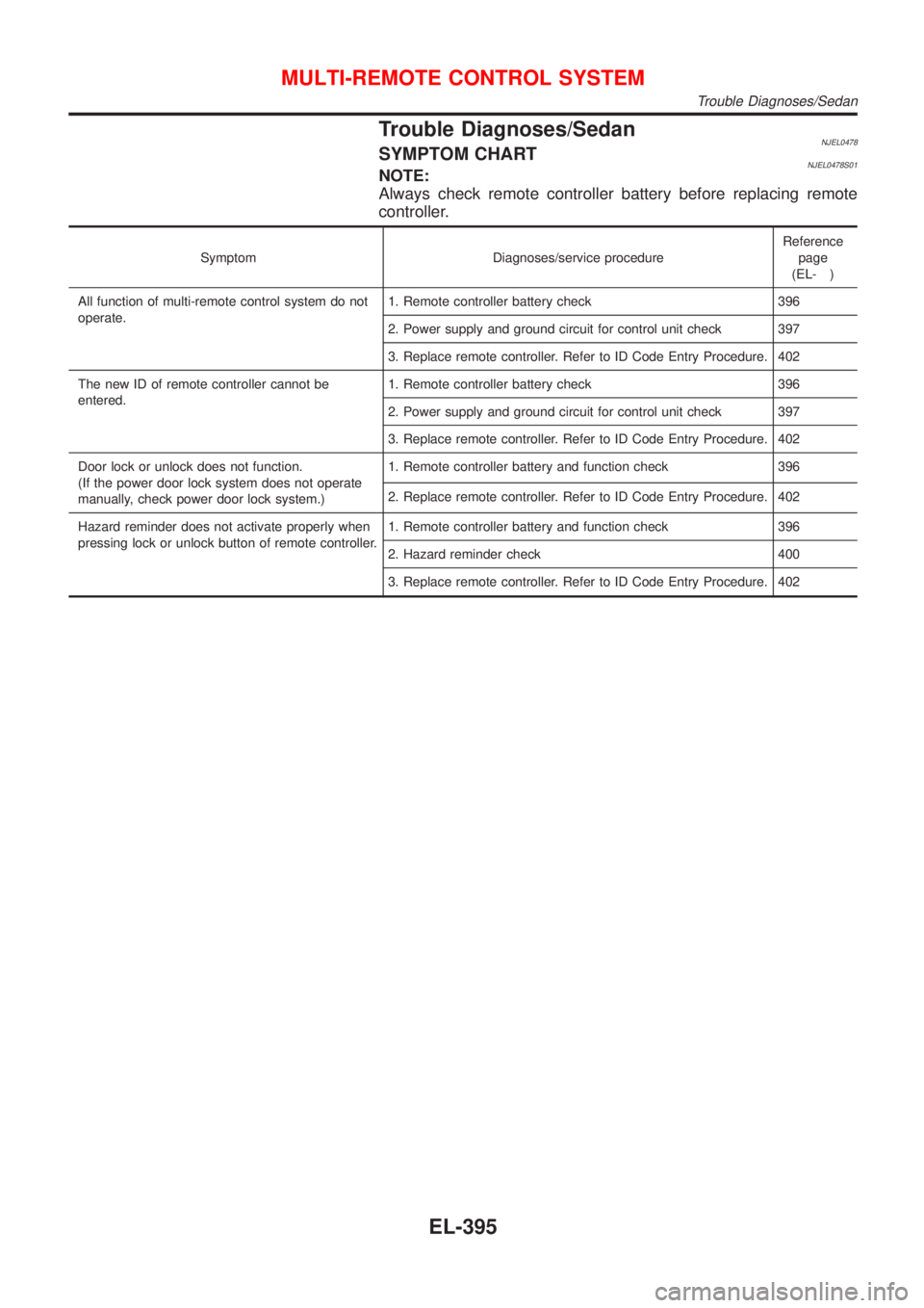
Trouble Diagnoses/SedanNJEL0478SYMPTOM CHARTNJEL0478S01NOTE:
Always check remote controller battery before replacing remote
controller.
Symptom Diagnoses/service procedureReference
page
(EL- )
All function of multi-remote control system do not
operate.1. Remote controller battery check 396
2. Power supply and ground circuit for control unit check 397
3. Replace remote controller. Refer to ID Code Entry Procedure. 402
The new ID of remote controller cannot be
entered.1. Remote controller battery check 396
2. Power supply and ground circuit for control unit check 397
3. Replace remote controller. Refer to ID Code Entry Procedure. 402
Door lock or unlock does not function.
(If the power door lock system does not operate
manually, check power door lock system.)1. Remote controller battery and function check 396
2. Replace remote controller. Refer to ID Code Entry Procedure. 402
Hazard reminder does not activate properly when
pressing lock or unlock button of remote controller.1. Remote controller battery and function check 396
2. Hazard reminder check 400
3. Replace remote controller. Refer to ID Code Entry Procedure. 402
MULTI-REMOTE CONTROL SYSTEM
Trouble Diagnoses/Sedan
EL-395
Page 1965 of 2898
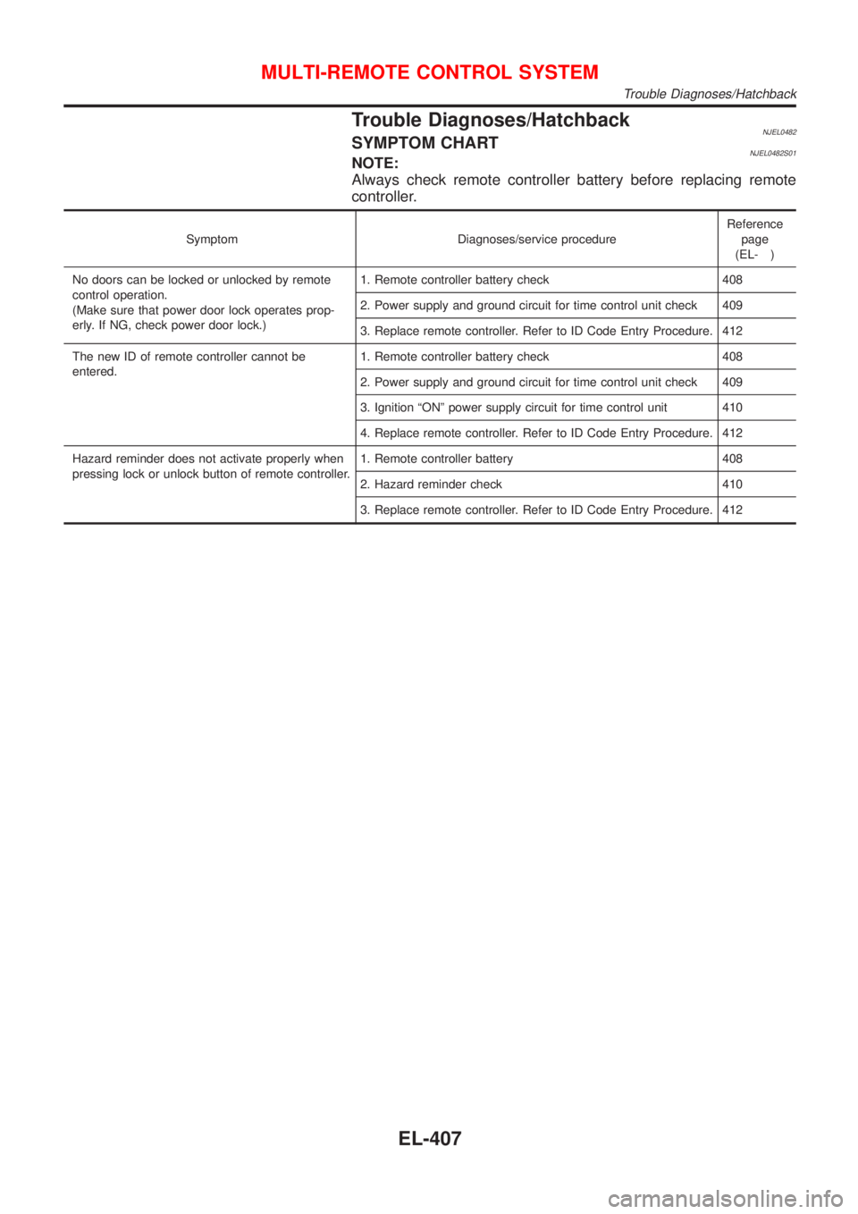
Trouble Diagnoses/HatchbackNJEL0482SYMPTOM CHARTNJEL0482S01NOTE:
Always check remote controller battery before replacing remote
controller.
Symptom Diagnoses/service procedureReference
page
(EL- )
No doors can be locked or unlocked by remote
control operation.
(Make sure that power door lock operates prop-
erly. If NG, check power door lock.)1. Remote controller battery check 408
2. Power supply and ground circuit for time control unit check 409
3. Replace remote controller. Refer to ID Code Entry Procedure. 412
The new ID of remote controller cannot be
entered.1. Remote controller battery check 408
2. Power supply and ground circuit for time control unit check 409
3. Ignition ªONº power supply circuit for time control unit 410
4. Replace remote controller. Refer to ID Code Entry Procedure. 412
Hazard reminder does not activate properly when
pressing lock or unlock button of remote controller.1. Remote controller battery 408
2. Hazard reminder check 410
3. Replace remote controller. Refer to ID Code Entry Procedure. 412
MULTI-REMOTE CONTROL SYSTEM
Trouble Diagnoses/Hatchback
EL-407
Page 1976 of 2898
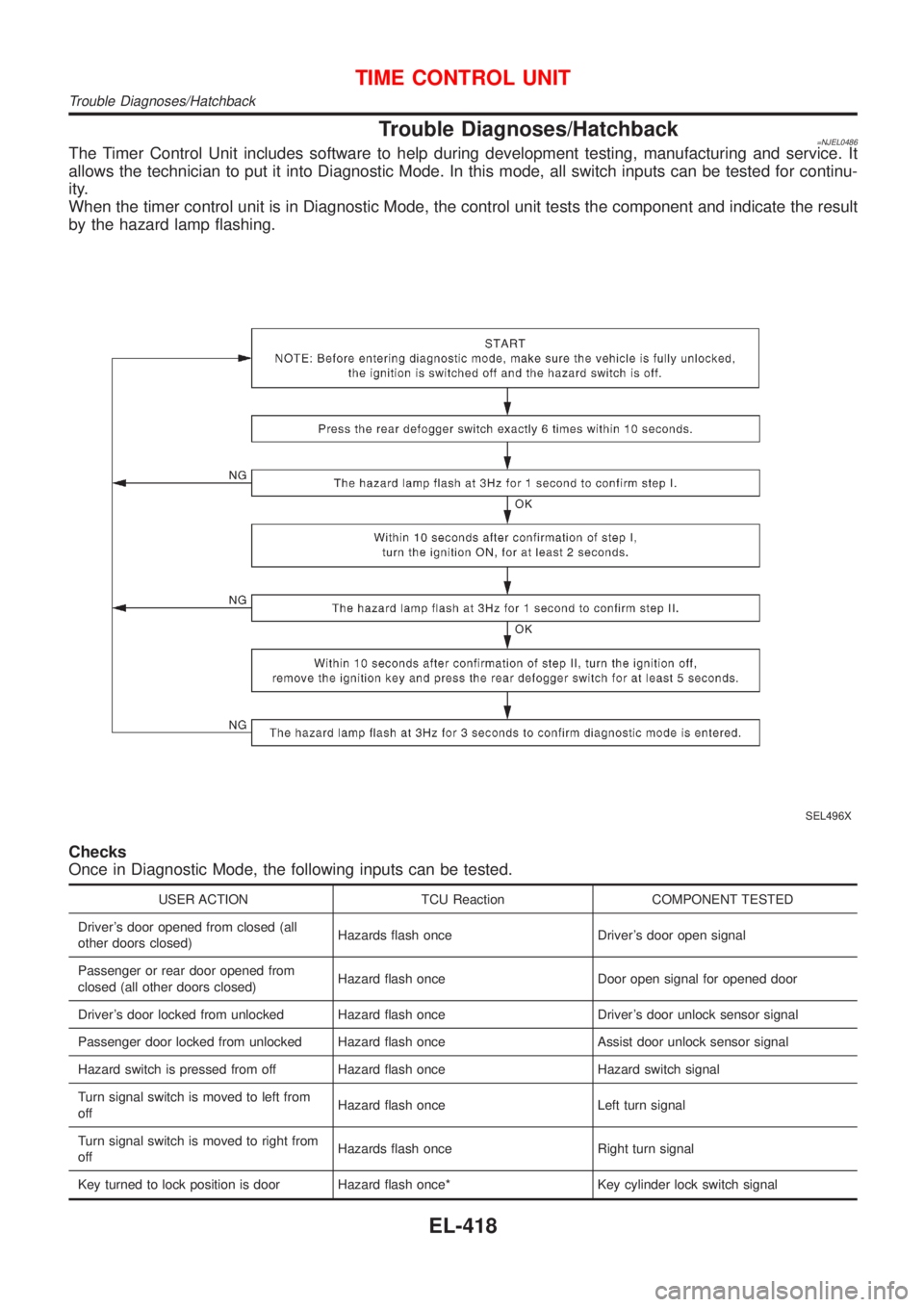
Trouble Diagnoses/Hatchback=NJEL0486The Timer Control Unit includes software to help during development testing, manufacturing and service. It
allows the technician to put it into Diagnostic Mode. In this mode, all switch inputs can be tested for continu-
ity.
When the timer control unit is in Diagnostic Mode, the control unit tests the component and indicate the result
by the hazard lamp flashing.
SEL496X
Checks
Once in Diagnostic Mode, the following inputs can be tested.
USER ACTION TCU Reaction COMPONENT TESTED
Driver's door opened from closed (all
other doors closed)Hazards flash once Driver's door open signal
Passenger or rear door opened from
closed (all other doors closed)Hazard flash once Door open signal for opened door
Driver's door locked from unlocked Hazard flash once Driver's door unlock sensor signal
Passenger door locked from unlocked Hazard flash once Assist door unlock sensor signal
Hazard switch is pressed from off Hazard flash once Hazard switch signal
Turn signal switch is moved to left from
offHazard flash once Left turn signal
Turn signal switch is moved to right from
offHazards flash once Right turn signal
Key turned to lock position is door Hazard flash once* Key cylinder lock switch signal
TIME CONTROL UNIT
Trouble Diagnoses/Hatchback
EL-418
Page 1987 of 2898
SEF094Y
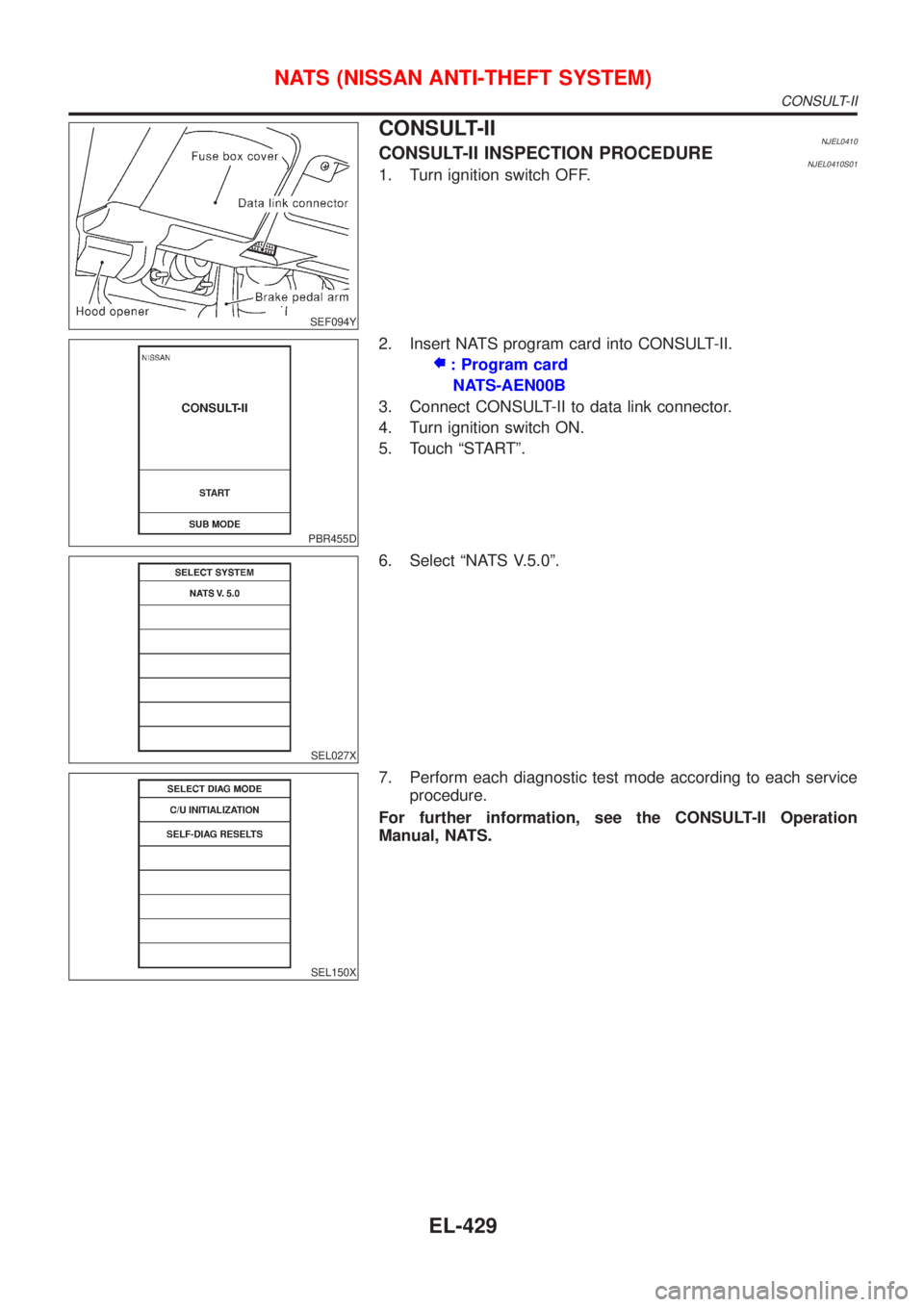
CONSULT-IINJEL0410CONSULT-II INSPECTION PROCEDURENJEL0410S011. Turn ignition switch OFF.
PBR455D
2. Insert NATS program card into CONSULT-II.
: Program card
NATS-AEN00B
3. Connect CONSULT-II to data link connector.
4. Turn ignition switch ON.
5. Touch ªSTARTº.
SEL027X
6. Select ªNATS V.5.0º.
SEL150X
7. Perform each diagnostic test mode according to each service
procedure.
For further information, see the CONSULT-II Operation
Manual, NATS.
NATS (NISSAN ANTI-THEFT SYSTEM)
CONSULT-II
EL-429
Page 2036 of 2898
SELF-DIAGNOSIS RESULTS=NJEL0519S03
Diagnosed
itemDisplayed
colorDetailed result DescriptionDiagnoses/service procedure
Recheck system at each check or
replacement (When malfunction is
eliminated, further repair work is
not required.)
ªGPS
Antennaº
(GPS
antenna
connection)Green ÐGPS antenna is connected to NAVI
control unit correctly.Ð
YellowConnection to the follow-
ing unit is abnormal. See
the Service Manual for
further diagnosis.GPS antenna connection error is
detected.1. Check GPS antenna feeder cable
connection at NAVI control unit.
2. Visually check GPS antenna
feeder cable. If NG, replace GPS
antenna assembly.
3. Replace GPS antenna.
ªNavigationºGreen Ð No failure is detected. Ð
Red [*** is abnormal.] NAVI control unit is malfunctioning. Replace NAVI control unit.
GraySelf-diagnosis for CD-
ROM DRIVER of NAVI
was not conducted due to
no insertion of CD-ROM.Any CD-ROM is not inserted or
NAVI control unit is malfunctioning.1. Confirm that map CD-ROM is not
inserted into NAVI control unit.
2. Replace NAVI control unit.
YellowCD-ROM or CD-ROM
DRIVER of NAVI is
abnormal. See the Ser-
vice Manual for further
diagnosis.NAVI control unit judges that
inserted CD-ROM is malfunctioning.
Map CD-ROM or CD-ROM driver of
the unit is malfunctioning.1. Confirm the disc is installed cor-
rectly (not up side down.)
2. Perform ªCheck the Map
CD-ROM version MODEº in
EL-484 to confirm whether cor-
rect CD-ROM is inserted or not.
3. Check the disc surface. Are there
any scratches, abrasions or pits
on the surface?
4. Replace the CD-ROM.
5. Replace NAVI control unit. CD-ROM is abnormal.
Please check the disc.Inserted map CD-ROM can not be
read.
Map CD-ROM or CD-ROM driver of
the unit is malfunctioning.
Connection to the follow-
ing unit is abnormal. See
the Service Manual for
further diagnosis.GPS antenna connection error is
detected.1. Check GPS antenna feeder cable
connection at NAVI control unit.
2. Visually check GPS antenna
feeder cable. If NG, replace GPS
antenna assembly.
3. Replace GPS antenna.
NOTE:
Connection between NAVI control unit and display unit should
be normal. Therefore, ªDisplay connection errorº will not
occur when the display can be opened or closed properly.
NAVIGATION SYSTEM
Self-diagnosis Mode (Cont'd)
EL-478
Page 2039 of 2898
ªHISTORY OF ERRORSº TABLE=NJEL0520S02
Detected items Description Diagnosis/service procedureRefer-
ence
page
Gyro sensor disconnectedCommunications malfunction between
NAVI control unit and internal gyroPerform self-diagnosis to confirm
whether the NAVI control unit is mal-
functioning or not. If no failure is
detected, a momentary and/or tempo-
rary malfunction may have been caused
by strong electromagnetic wave interfer-
ence.EL-476
Connection problem of speed
sensorInput malfunction of NAVI control unit
and speed sensorCheck vehicle speed sensor signal in
ªDiagnosis for signals from the carº
mode. If the input signal is not detected
correctly, check harness for open or
short between combination meter and
NAVI control unit.EL-483
GPS disconnected
Communications malfunction between
NAVI control unit and GPS boardPerform self-diagnosis to confirm
whether the NAVI control unit is mal-
functioning or not. If no failure is
detected, a momentary and/or tempo-
rary malfunction may have been caused
by strong electromagnetic wave interfer-
ence.EL-476 GPS transmission cable malfunc-
tion
GPS input line connection error
GPS TCXO overThe transmission circuit of the GPS
board frequency synchronization oscilla-
tor (inside the NAVI control unit) is send-
ing an oscillation frequency that is
greater or less than the set value.A location error occurs. Strong electro-
magnetic wave interference may have
occurred. The GPS antenna may be in a
very hot or very cold environment. This
is usually a temporary malfunction.Ð
GPS TCXO under
GPS ROM malfunction
Internal malfunction of GPS board RAM
or ROM inside the NAVI control unit.Perform self-diagnosis to confirm
whether the NAVI control unit is mal-
functioning or not. If no failure is
detected, a momentary and/or tempo-
rary malfunction may have been caused
by strong electromagnetic wave interfer-
ence.EL-476 GPS RAM malfunction
GPS RTC malfunctionMalfunction of GPS board clock IC
inside the NAVI control unit.
GPS antenna disconnected ÐPerform self-diagnosis to confirm GPS
antenna connection. If no failure is
detected, a momentary and/or tempo-
rary malfunction may have been caused
by a strong impact.EL-476
Low voltage of GPSPower supply voltage for GPS board
inside the NAVI control unit is low.1. Check power supply circuits for NAVI
control unit.EL-504
2. Perform self-diagnosis to confirm
GPS antenna connection.EL-476
3. If above diagnosis results are OK, a
momentary and/or temporary malfunc-
tion may have been caused by a strong
impact.Ð
CD-ROM communication errorCD-ROM driver malfunction (inside the
NAVI control unit)Perform self-diagnosis to confirm
whether the NAVI control unit is mal-
functioning or not. If no failure is
detected, a momentary and/or tempo-
rary malfunction may have been caused
by strong electromagnetic wave interfer-
ence.EL-476
NAVIGATION SYSTEM
Confirmation/Adjustment Mode (Cont'd)
EL-481