2001 NISSAN ALMERA lights
[x] Cancel search: lightsPage 1029 of 2898
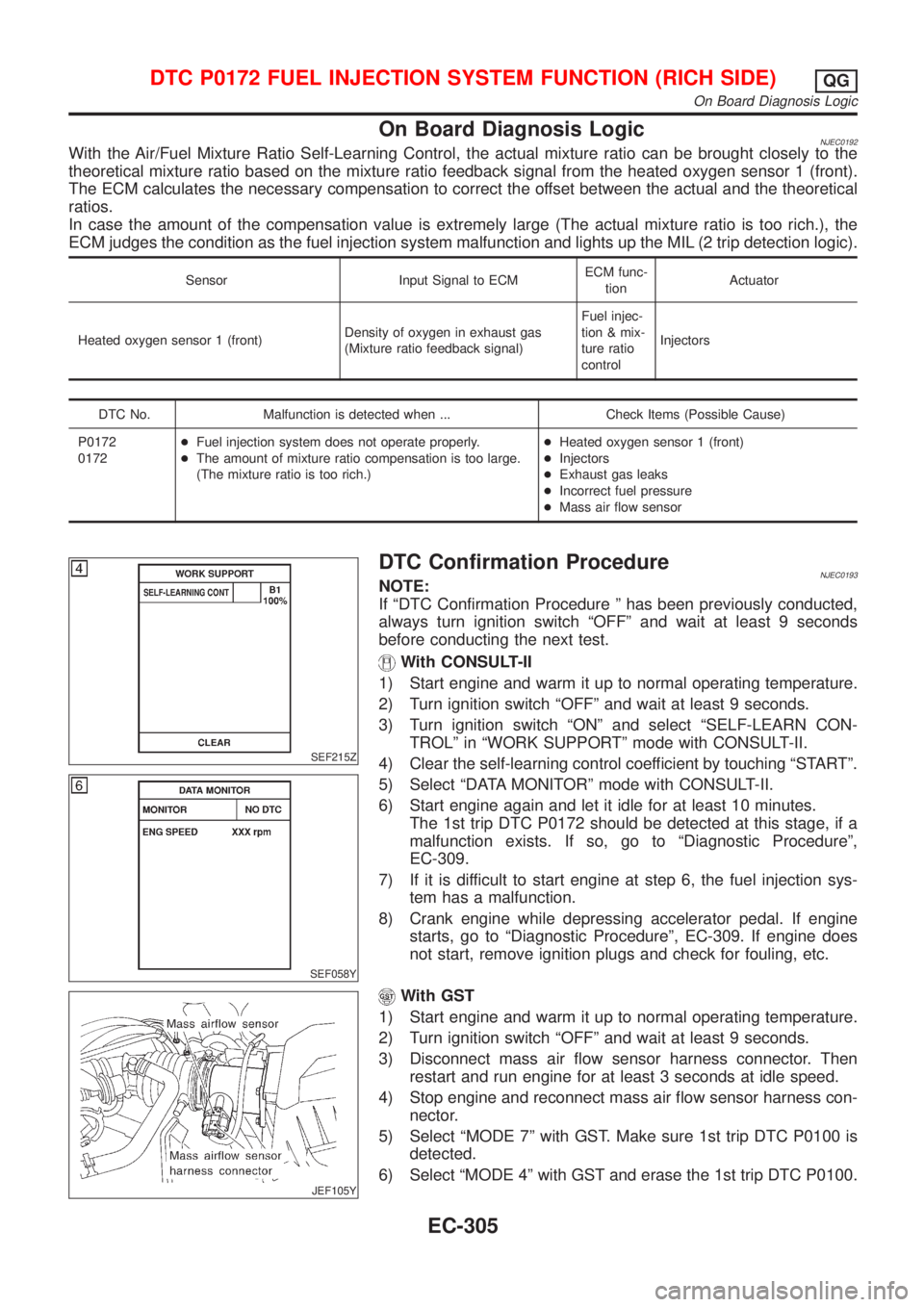
On Board Diagnosis LogicNJEC0192With the Air/Fuel Mixture Ratio Self-Learning Control, the actual mixture ratio can be brought closely to the
theoretical mixture ratio based on the mixture ratio feedback signal from the heated oxygen sensor 1 (front).
The ECM calculates the necessary compensation to correct the offset between the actual and the theoretical
ratios.
In case the amount of the compensation value is extremely large (The actual mixture ratio is too rich.), the
ECM judges the condition as the fuel injection system malfunction and lights up the MIL (2 trip detection logic).
Sensor Input Signal to ECMECM func-
tionActuator
Heated oxygen sensor 1 (front)Density of oxygen in exhaust gas
(Mixture ratio feedback signal)Fuel injec-
tion & mix-
ture ratio
controlInjectors
DTC No. Malfunction is detected when ... Check Items (Possible Cause)
P0172
0172+Fuel injection system does not operate properly.
+The amount of mixture ratio compensation is too large.
(The mixture ratio is too rich.)+Heated oxygen sensor 1 (front)
+Injectors
+Exhaust gas leaks
+Incorrect fuel pressure
+Mass air flow sensor
SEF215Z
SEF058Y
DTC Confirmation ProcedureNJEC0193NOTE:
If ªDTC Confirmation Procedure º has been previously conducted,
always turn ignition switch ªOFFº and wait at least 9 seconds
before conducting the next test.
With CONSULT-II
1) Start engine and warm it up to normal operating temperature.
2) Turn ignition switch ªOFFº and wait at least 9 seconds.
3) Turn ignition switch ªONº and select ªSELF-LEARN CON-
TROLº in ªWORK SUPPORTº mode with CONSULT-II.
4) Clear the self-learning control coefficient by touching ªSTARTº.
5) Select ªDATA MONITORº mode with CONSULT-II.
6) Start engine again and let it idle for at least 10 minutes.
The 1st trip DTC P0172 should be detected at this stage, if a
malfunction exists. If so, go to ªDiagnostic Procedureº,
EC-309.
7) If it is difficult to start engine at step 6, the fuel injection sys-
tem has a malfunction.
8) Crank engine while depressing accelerator pedal. If engine
starts, go to ªDiagnostic Procedureº, EC-309. If engine does
not start, remove ignition plugs and check for fouling, etc.
JEF105Y
With GST
1) Start engine and warm it up to normal operating temperature.
2) Turn ignition switch ªOFFº and wait at least 9 seconds.
3) Disconnect mass air flow sensor harness connector. Then
restart and run engine for at least 3 seconds at idle speed.
4) Stop engine and reconnect mass air flow sensor harness con-
nector.
5) Select ªMODE 7º with GST. Make sure 1st trip DTC P0100 is
detected.
6) Select ªMODE 4º with GST and erase the 1st trip DTC P0100.
DTC P0172 FUEL INJECTION SYSTEM FUNCTION (RICH SIDE)QG
On Board Diagnosis Logic
EC-305
Page 1317 of 2898
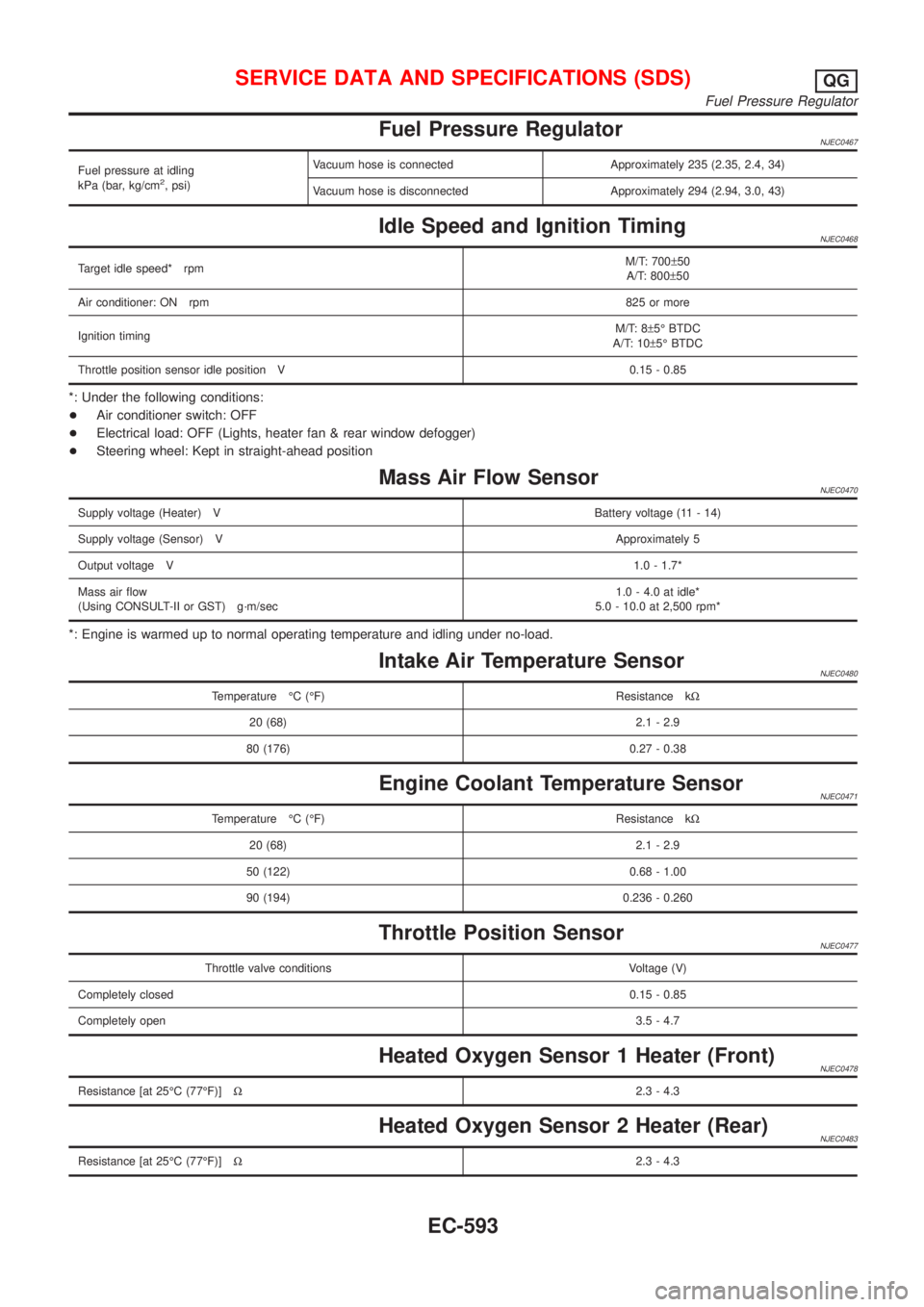
Fuel Pressure RegulatorNJEC0467
Fuel pressure at idling
kPa (bar, kg/cm2, psi)Vacuum hose is connected Approximately 235 (2.35, 2.4, 34)
Vacuum hose is disconnected Approximately 294 (2.94, 3.0, 43)
Idle Speed and Ignition TimingNJEC0468
Target idle speed* rpmM/T: 700±50
A/T: 800±50
Air conditioner: ON rpm825 or more
Ignition timingM/T: 8±5É BTDC
A/T: 10±5É BTDC
Throttle position sensor idle position V 0.15 - 0.85
*: Under the following conditions:
+Air conditioner switch: OFF
+Electrical load: OFF (Lights, heater fan & rear window defogger)
+Steering wheel: Kept in straight-ahead position
Mass Air Flow SensorNJEC0470
Supply voltage (Heater) VBattery voltage (11 - 14)
Supply voltage (Sensor) VApproximately 5
Output voltage V1.0 - 1.7*
Mass air flow
(Using CONSULT-II or GST) g´m/sec1.0 - 4.0 at idle*
5.0 - 10.0 at 2,500 rpm*
*: Engine is warmed up to normal operating temperature and idling under no-load.
Intake Air Temperature SensorNJEC0480
Temperature ÉC (ÉF) Resistance kW
20 (68) 2.1 - 2.9
80 (176) 0.27 - 0.38
Engine Coolant Temperature SensorNJEC0471
Temperature ÉC (ÉF) Resistance kW
20 (68) 2.1 - 2.9
50 (122) 0.68 - 1.00
90 (194) 0.236 - 0.260
Throttle Position SensorNJEC0477
Throttle valve conditions Voltage (V)
Completely closed0.15 - 0.85
Completely open3.5 - 4.7
Heated Oxygen Sensor 1 Heater (Front)NJEC0478
Resistance [at 25ÉC (77ÉF)]W2.3 - 4.3
Heated Oxygen Sensor 2 Heater (Rear)NJEC0483
Resistance [at 25ÉC (77ÉF)]W2.3 - 4.3
SERVICE DATA AND SPECIFICATIONS (SDS)QG
Fuel Pressure Regulator
EC-593
Page 1349 of 2898
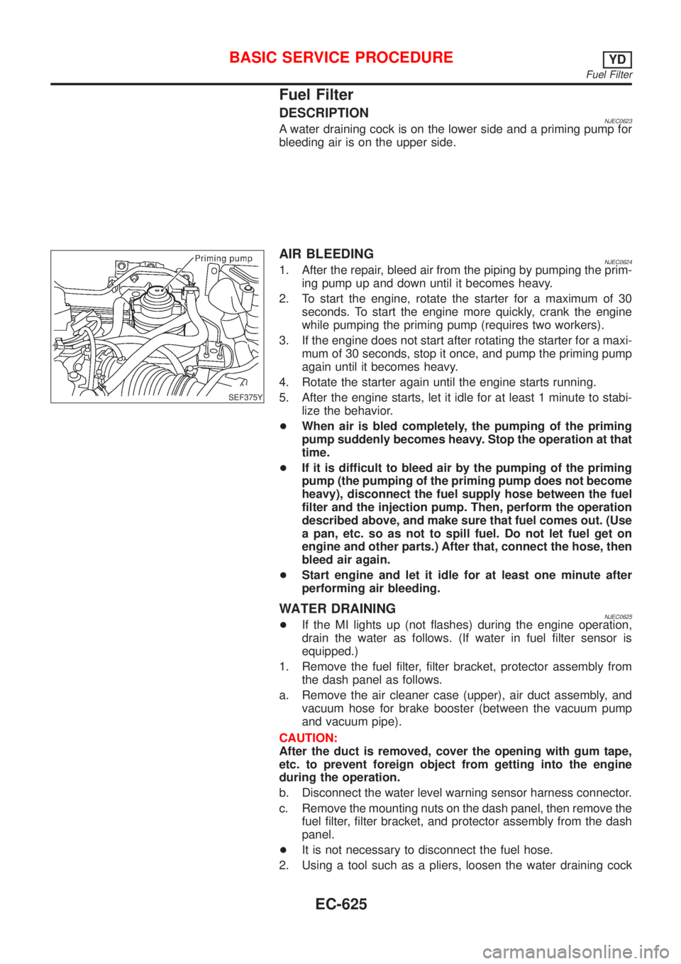
Fuel Filter
DESCRIPTIONNJEC0623A water draining cock is on the lower side and a priming pump for
bleeding air is on the upper side.
SEF375Y
AIR BLEEDINGNJEC06241. After the repair, bleed air from the piping by pumping the prim-
ing pump up and down until it becomes heavy.
2. To start the engine, rotate the starter for a maximum of 30
seconds. To start the engine more quickly, crank the engine
while pumping the priming pump (requires two workers).
3. If the engine does not start after rotating the starter for a maxi-
mum of 30 seconds, stop it once, and pump the priming pump
again until it becomes heavy.
4. Rotate the starter again until the engine starts running.
5. After the engine starts, let it idle for at least 1 minute to stabi-
lize the behavior.
+When air is bled completely, the pumping of the priming
pump suddenly becomes heavy. Stop the operation at that
time.
+If it is difficult to bleed air by the pumping of the priming
pump (the pumping of the priming pump does not become
heavy), disconnect the fuel supply hose between the fuel
filter and the injection pump. Then, perform the operation
described above, and make sure that fuel comes out. (Use
a pan, etc. so as not to spill fuel. Do not let fuel get on
engine and other parts.) After that, connect the hose, then
bleed air again.
+Start engine and let it idle for at least one minute after
performing air bleeding.
WATER DRAININGNJEC0625+If the MI lights up (not flashes) during the engine operation,
drain the water as follows. (If water in fuel filter sensor is
equipped.)
1. Remove the fuel filter, filter bracket, protector assembly from
the dash panel as follows.
a. Remove the air cleaner case (upper), air duct assembly, and
vacuum hose for brake booster (between the vacuum pump
and vacuum pipe).
CAUTION:
After the duct is removed, cover the opening with gum tape,
etc. to prevent foreign object from getting into the engine
during the operation.
b. Disconnect the water level warning sensor harness connector.
c. Remove the mounting nuts on the dash panel, then remove the
fuel filter, filter bracket, and protector assembly from the dash
panel.
+It is not necessary to disconnect the fuel hose.
2. Using a tool such as a pliers, loosen the water draining cock
BASIC SERVICE PROCEDUREYD
Fuel Filter
EC-625
Page 1350 of 2898
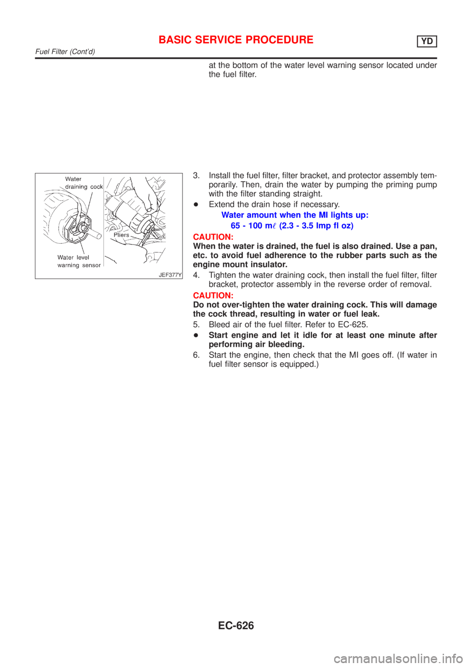
at the bottom of the water level warning sensor located under
the fuel filter.
JEF377Y
3. Install the fuel filter, filter bracket, and protector assembly tem-
porarily. Then, drain the water by pumping the priming pump
with the filter standing straight.
+Extend the drain hose if necessary.
Water amount when the MI lights up:
65 - 100 m!(2.3 - 3.5 Imp fl oz)
CAUTION:
When the water is drained, the fuel is also drained. Use a pan,
etc. to avoid fuel adherence to the rubber parts such as the
engine mount insulator.
4. Tighten the water draining cock, then install the fuel filter, filter
bracket, protector assembly in the reverse order of removal.
CAUTION:
Do not over-tighten the water draining cock. This will damage
the cock thread, resulting in water or fuel leak.
5. Bleed air of the fuel filter. Refer to EC-625.
+Start engine and let it idle for at least one minute after
performing air bleeding.
6. Start the engine, then check that the MI goes off. (If water in
fuel filter sensor is equipped.)
BASIC SERVICE PROCEDUREYD
Fuel Filter (Cont'd)
EC-626
Page 1981 of 2898
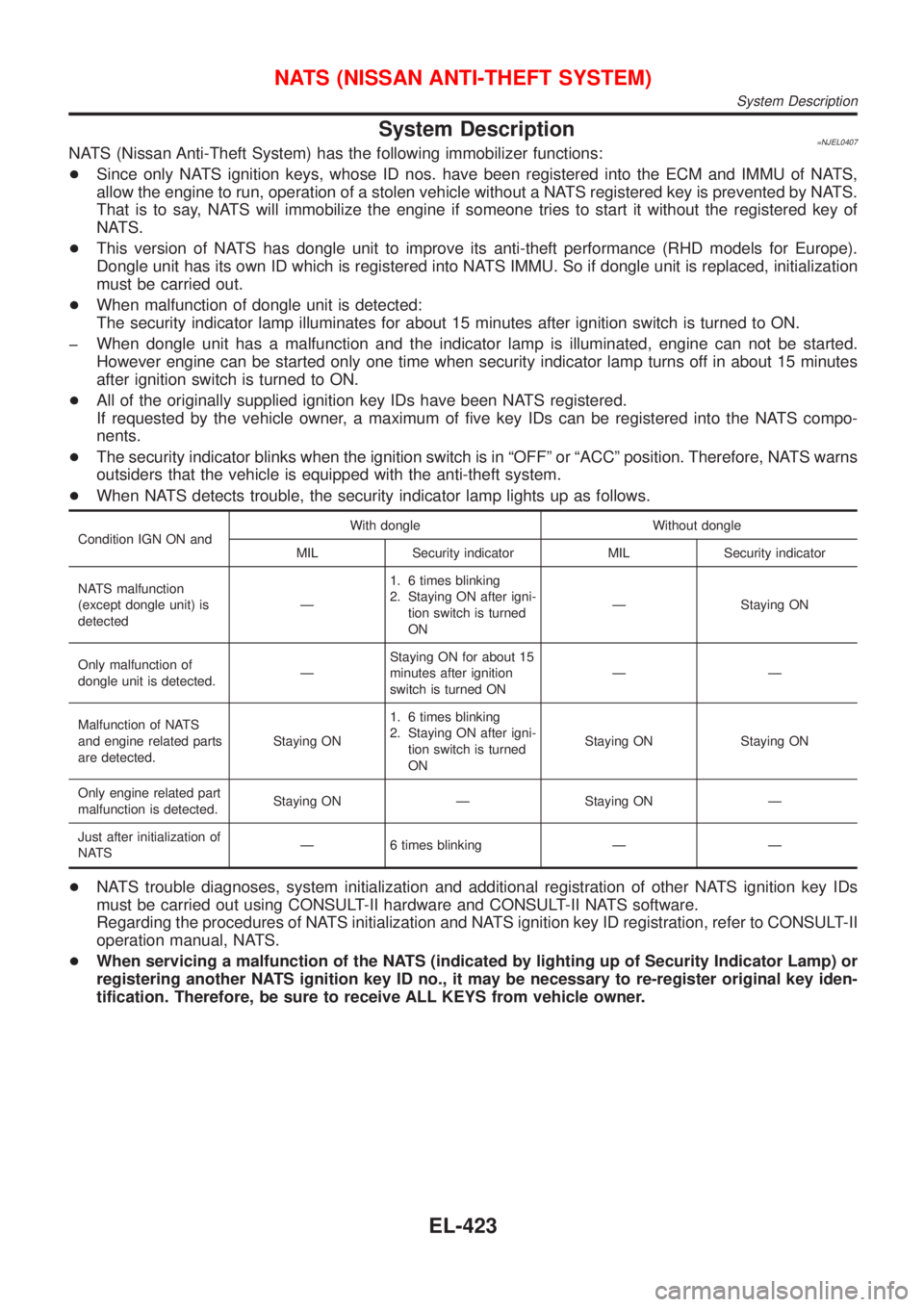
System Description=NJEL0407NATS (Nissan Anti-Theft System) has the following immobilizer functions:
+Since only NATS ignition keys, whose ID nos. have been registered into the ECM and IMMU of NATS,
allow the engine to run, operation of a stolen vehicle without a NATS registered key is prevented by NATS.
That is to say, NATS will immobilize the engine if someone tries to start it without the registered key of
NATS.
+This version of NATS has dongle unit to improve its anti-theft performance (RHD models for Europe).
Dongle unit has its own ID which is registered into NATS IMMU. So if dongle unit is replaced, initialization
must be carried out.
+When malfunction of dongle unit is detected:
The security indicator lamp illuminates for about 15 minutes after ignition switch is turned to ON.
þ When dongle unit has a malfunction and the indicator lamp is illuminated, engine can not be started.
However engine can be started only one time when security indicator lamp turns off in about 15 minutes
after ignition switch is turned to ON.
+All of the originally supplied ignition key IDs have been NATS registered.
If requested by the vehicle owner, a maximum of five key IDs can be registered into the NATS compo-
nents.
+The security indicator blinks when the ignition switch is in ªOFFº or ªACCº position. Therefore, NATS warns
outsiders that the vehicle is equipped with the anti-theft system.
+When NATS detects trouble, the security indicator lamp lights up as follows.
Condition IGN ON andWith dongle Without dongle
MIL Security indicator MIL Security indicator
NATS malfunction
(except dongle unit) is
detectedÐ1. 6 times blinking
2. Staying ON after igni-
tion switch is turned
ONÐ Staying ON
Only malfunction of
dongle unit is detected.ÐStaying ON for about 15
minutes after ignition
switch is turned ONÐÐ
Malfunction of NATS
and engine related parts
are detected.Staying ON1. 6 times blinking
2. Staying ON after igni-
tion switch is turned
ONStaying ON Staying ON
Only engine related part
malfunction is detected.Staying ON Ð Staying ON Ð
Just after initialization of
NATSÐ 6 times blinking Ð Ð
+NATS trouble diagnoses, system initialization and additional registration of other NATS ignition key IDs
must be carried out using CONSULT-II hardware and CONSULT-II NATS software.
Regarding the procedures of NATS initialization and NATS ignition key ID registration, refer to CONSULT-II
operation manual, NATS.
+When servicing a malfunction of the NATS (indicated by lighting up of Security Indicator Lamp) or
registering another NATS ignition key ID no., it may be necessary to re-register original key iden-
tification. Therefore, be sure to receive ALL KEYS from vehicle owner.
NATS (NISSAN ANTI-THEFT SYSTEM)
System Description
EL-423
Page 1992 of 2898
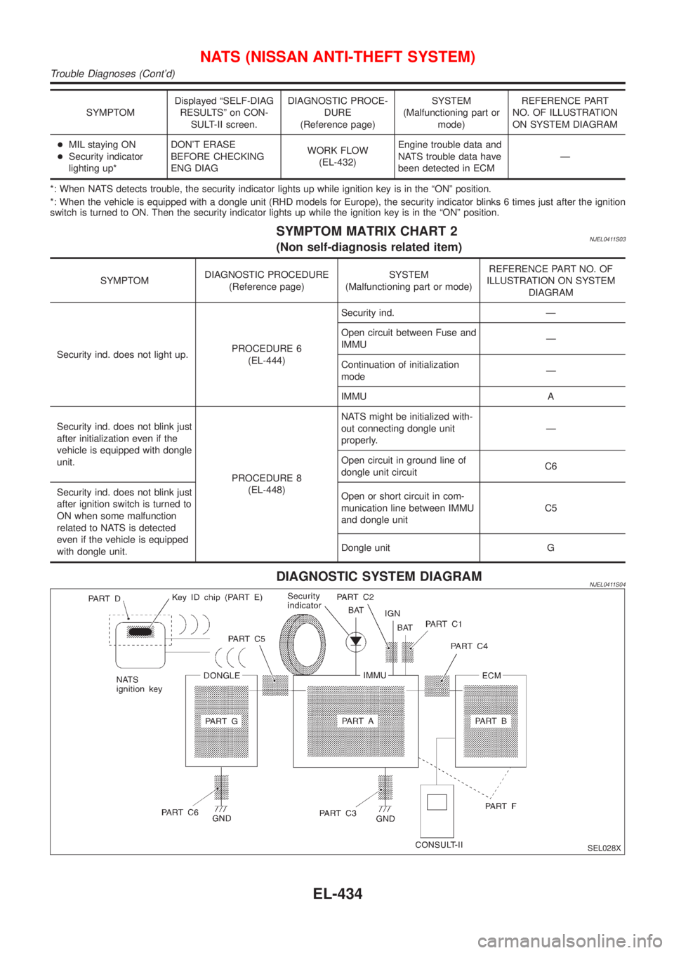
SYMPTOMDisplayed ªSELF-DIAG
RESULTSº on CON-
SULT-II screen.DIAGNOSTIC PROCE-
DURE
(Reference page)SYSTEM
(Malfunctioning part or
mode)REFERENCE PART
NO. OF ILLUSTRATION
ON SYSTEM DIAGRAM
+MIL staying ON
+Security indicator
lighting up*DON'T ERASE
BEFORE CHECKING
ENG DIAGWORK FLOW
(EL-432)Engine trouble data and
NATS trouble data have
been detected in ECMÐ
*: When NATS detects trouble, the security indicator lights up while ignition key is in the ªONº position.
*: When the vehicle is equipped with a dongle unit (RHD models for Europe), the security indicator blinks 6 times just after the ignition
switch is turned to ON. Then the security indicator lights up while the ignition key is in the ªONº position.
SYMPTOM MATRIX CHART 2NJEL0411S03(Non self-diagnosis related item)
SYMPTOMDIAGNOSTIC PROCEDURE
(Reference page)SYSTEM
(Malfunctioning part or mode)REFERENCE PART NO. OF
ILLUSTRATION ON SYSTEM
DIAGRAM
Security ind. does not light up.PROCEDURE 6
(EL-444)Security ind. Ð
Open circuit between Fuse and
IMMUÐ
Continuation of initialization
modeÐ
IMMU A
Security ind. does not blink just
after initialization even if the
vehicle is equipped with dongle
unit.
PROCEDURE 8
(EL-448)NATS might be initialized with-
out connecting dongle unit
properly.Ð
Open circuit in ground line of
dongle unit circuitC6
Security ind. does not blink just
after ignition switch is turned to
ON when some malfunction
related to NATS is detected
even if the vehicle is equipped
with dongle unit.Open or short circuit in com-
munication line between IMMU
and dongle unitC5
Dongle unit G
DIAGNOSTIC SYSTEM DIAGRAMNJEL0411S04
SEL028X
NATS (NISSAN ANTI-THEFT SYSTEM)
Trouble Diagnoses (Cont'd)
EL-434
Page 2071 of 2898
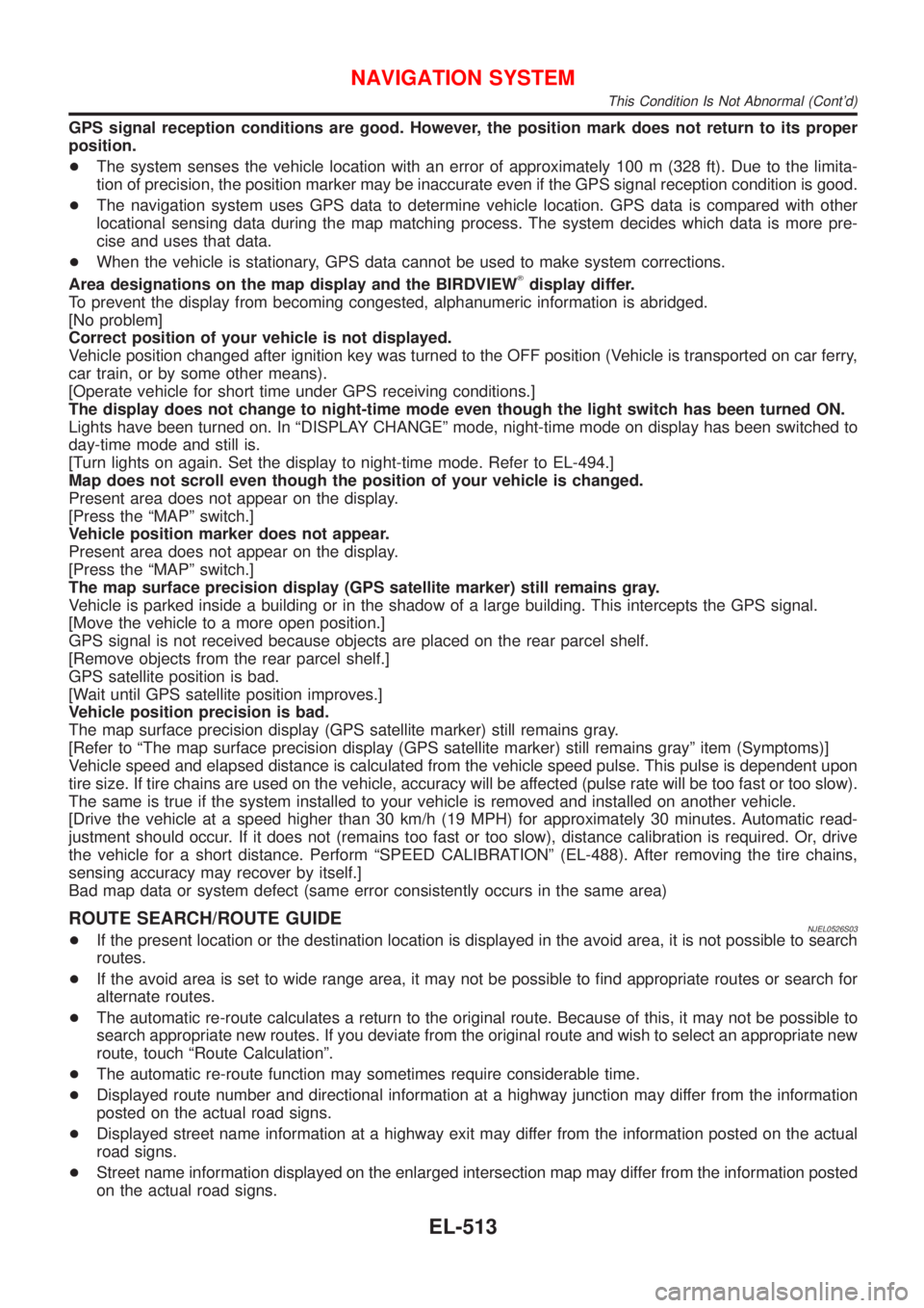
GPS signal reception conditions are good. However, the position mark does not return to its proper
position.
+The system senses the vehicle location with an error of approximately 100 m (328 ft). Due to the limita-
tion of precision, the position marker may be inaccurate even if the GPS signal reception condition is good.
+The navigation system uses GPS data to determine vehicle location. GPS data is compared with other
locational sensing data during the map matching process. The system decides which data is more pre-
cise and uses that data.
+When the vehicle is stationary, GPS data cannot be used to make system corrections.
Area designations on the map display and the BIRDVIEW
Tdisplay differ.
To prevent the display from becoming congested, alphanumeric information is abridged.
[No problem]
Correct position of your vehicle is not displayed.
Vehicle position changed after ignition key was turned to the OFF position (Vehicle is transported on car ferry,
car train, or by some other means).
[Operate vehicle for short time under GPS receiving conditions.]
The display does not change to night-time mode even though the light switch has been turned ON.
Lights have been turned on. In ªDISPLAY CHANGEº mode, night-time mode on display has been switched to
day-time mode and still is.
[Turn lights on again. Set the display to night-time mode. Refer to EL-494.]
Map does not scroll even though the position of your vehicle is changed.
Present area does not appear on the display.
[Press the ªMAPº switch.]
Vehicle position marker does not appear.
Present area does not appear on the display.
[Press the ªMAPº switch.]
The map surface precision display (GPS satellite marker) still remains gray.
Vehicle is parked inside a building or in the shadow of a large building. This intercepts the GPS signal.
[Move the vehicle to a more open position.]
GPS signal is not received because objects are placed on the rear parcel shelf.
[Remove objects from the rear parcel shelf.]
GPS satellite position is bad.
[Wait until GPS satellite position improves.]
Vehicle position precision is bad.
The map surface precision display (GPS satellite marker) still remains gray.
[Refer to ªThe map surface precision display (GPS satellite marker) still remains grayº item (Symptoms)]
Vehicle speed and elapsed distance is calculated from the vehicle speed pulse. This pulse is dependent upon
tire size. If tire chains are used on the vehicle, accuracy will be affected (pulse rate will be too fast or too slow).
The same is true if the system installed to your vehicle is removed and installed on another vehicle.
[Drive the vehicle at a speed higher than 30 km/h (19 MPH) for approximately 30 minutes. Automatic read-
justment should occur. If it does not (remains too fast or too slow), distance calibration is required. Or, drive
the vehicle for a short distance. Perform ªSPEED CALIBRATIONº (EL-488). After removing the tire chains,
sensing accuracy may recover by itself.]
Bad map data or system defect (same error consistently occurs in the same area)
ROUTE SEARCH/ROUTE GUIDENJEL0526S03+If the present location or the destination location is displayed in the avoid area, it is not possible to search
routes.
+If the avoid area is set to wide range area, it may not be possible to find appropriate routes or search for
alternate routes.
+The automatic re-route calculates a return to the original route. Because of this, it may not be possible to
search appropriate new routes. If you deviate from the original route and wish to select an appropriate new
route, touch ªRoute Calculationº.
+The automatic re-route function may sometimes require considerable time.
+Displayed route number and directional information at a highway junction may differ from the information
posted on the actual road signs.
+Displayed street name information at a highway exit may differ from the information posted on the actual
road signs.
+Street name information displayed on the enlarged intersection map may differ from the information posted
on the actual road signs.
NAVIGATION SYSTEM
This Condition Is Not Abnormal (Cont'd)
EL-513
Page 2350 of 2898
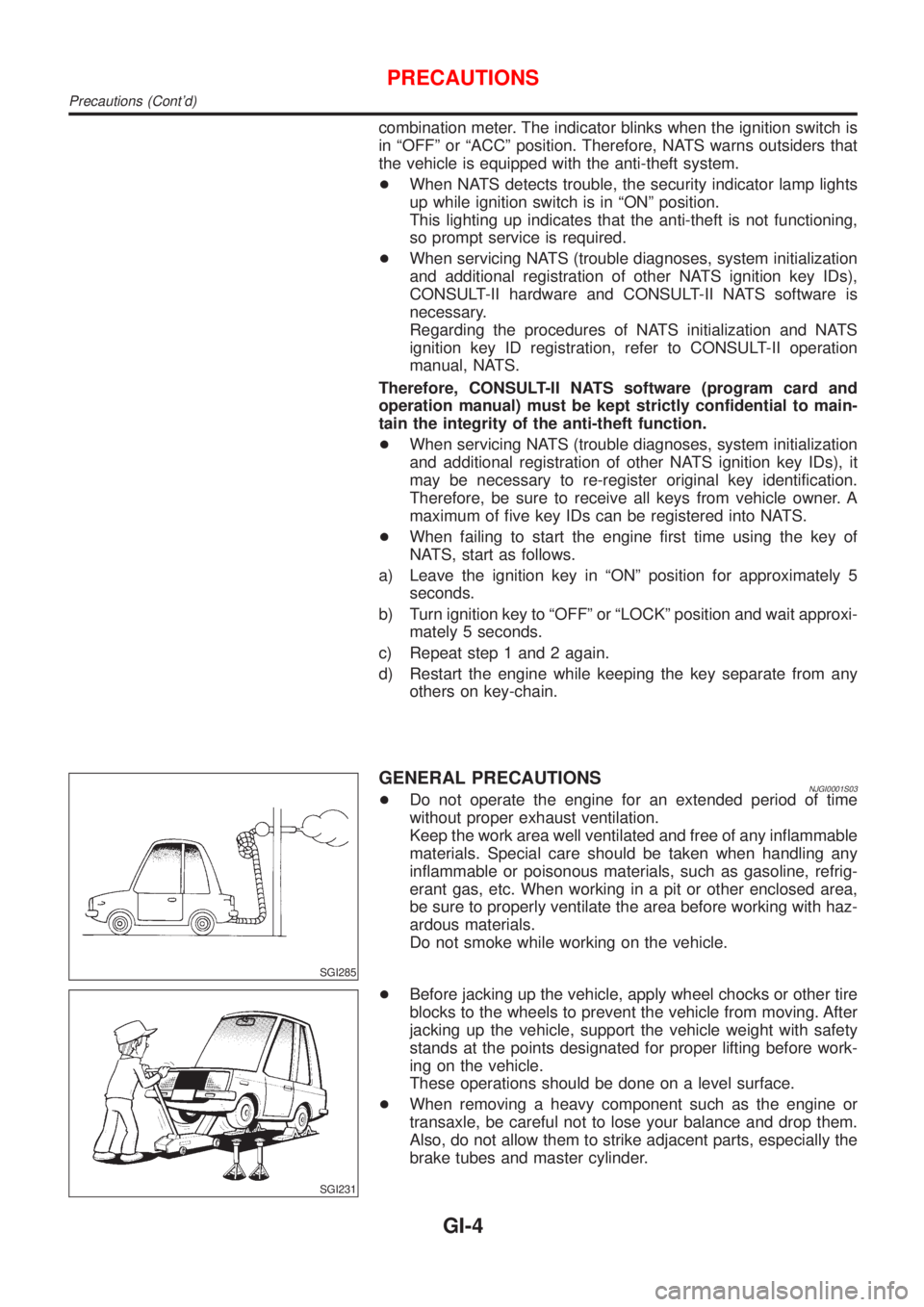
combination meter. The indicator blinks when the ignition switch is
in ªOFFº or ªACCº position. Therefore, NATS warns outsiders that
the vehicle is equipped with the anti-theft system.
+When NATS detects trouble, the security indicator lamp lights
up while ignition switch is in ªONº position.
This lighting up indicates that the anti-theft is not functioning,
so prompt service is required.
+When servicing NATS (trouble diagnoses, system initialization
and additional registration of other NATS ignition key IDs),
CONSULT-II hardware and CONSULT-II NATS software is
necessary.
Regarding the procedures of NATS initialization and NATS
ignition key ID registration, refer to CONSULT-II operation
manual, NATS.
Therefore, CONSULT-II NATS software (program card and
operation manual) must be kept strictly confidential to main-
tain the integrity of the anti-theft function.
+When servicing NATS (trouble diagnoses, system initialization
and additional registration of other NATS ignition key IDs), it
may be necessary to re-register original key identification.
Therefore, be sure to receive all keys from vehicle owner. A
maximum of five key IDs can be registered into NATS.
+When failing to start the engine first time using the key of
NATS, start as follows.
a) Leave the ignition key in ªONº position for approximately 5
seconds.
b) Turn ignition key to ªOFFº or ªLOCKº position and wait approxi-
mately 5 seconds.
c) Repeat step 1 and 2 again.
d) Restart the engine while keeping the key separate from any
others on key-chain.
SGI285
GENERAL PRECAUTIONSNJGI0001S03+Do not operate the engine for an extended period of time
without proper exhaust ventilation.
Keep the work area well ventilated and free of any inflammable
materials. Special care should be taken when handling any
inflammable or poisonous materials, such as gasoline, refrig-
erant gas, etc. When working in a pit or other enclosed area,
be sure to properly ventilate the area before working with haz-
ardous materials.
Do not smoke while working on the vehicle.
SGI231
+Before jacking up the vehicle, apply wheel chocks or other tire
blocks to the wheels to prevent the vehicle from moving. After
jacking up the vehicle, support the vehicle weight with safety
stands at the points designated for proper lifting before work-
ing on the vehicle.
These operations should be done on a level surface.
+When removing a heavy component such as the engine or
transaxle, be careful not to lose your balance and drop them.
Also, do not allow them to strike adjacent parts, especially the
brake tubes and master cylinder.
PRECAUTIONS
Precautions (Cont'd)
GI-4