Page 104 of 2898
2 CHECK ENGINE BRAKE
Does vehicle decelerate by engine brake?
SAT776BA
YesorNo
Ye s©GO TO 3.
No©Go to ª15. Engine Speed Does Not Return To Idle (Light Braking D
4®D3)º, AT-328.
Continue ROAD TEST.
3 CHECK SHIFT DOWN (D3TO D2)
1. Move selector lever from ªDº to ª2º position while driving in D3(O/D OFF).
2. Does A/T shift from D
3(O/D OFF) to 22?
Read gear position.
SAT791GA
YesorNo
Ye s©GO TO 4.
No©Go to ª18. A/T Does Not Shift: D
3®D2, When Selector Lever ªDº®ª2º Positionº,
AT-332. Continue ROAD TEST.
TROUBLE DIAGNOSIS Ð BASIC INSPECTION
Road Test (Cont'd)
AT-102
Page 105 of 2898
4 CHECK ENGINE BRAKE
Does vehicle decelerate by engine brake?
SAT791GA
YesorNo
Ye s©GO TO 5.
No©Go to ª15. Engine Speed Does Not Return To Idle (Light Braking D
4®D3)º, AT-328.
Continue ROAD TEST.
5 CHECK SHIFT DOWN
1. Move selector lever from ª2º to ª1º position while driving in 22.
2. Does A/T shift from 2
2to 11position?
Read gear position.
SAT778B
YesorNo
Ye s©GO TO 6.
No©Go to ª19. A/T Does Not Shift: 2
2®11, When Selector lever ª2º®ª1º Positionº, AT-333.
Continue ROAD TEST.
TROUBLE DIAGNOSIS Ð BASIC INSPECTION
Road Test (Cont'd)
AT-103
Page 330 of 2898
15. Engine Speed Does Not Return To Idle
(Light Braking D
4®D3)=NJAT0345SYMPTOM:
+Engine speed does not smoothly return to idle when A/T
shifts from D
4to D3.
+Vehicle does not decelerate by engine brake when turning
overdrive control switch OFF.
+Vehicle does not decelerate by engine brake when shifting
A/T from ªDº to ª2º position.
1 CHECK SELF-DIAGNOSTIC RESULTS
Does self-diagnosis show damage to overrun clutch solenoid valve circuit after cruise test?
SAT348H
YesorNO
Ye s©Check overrun clutch solenoid valve circuit. Refer to AT-154 (General and except for
Euro-OBD)/AT-268 (Euro-OBD).
No©GO TO 2.
2 CHECK THROTTLE POSITION SENSOR
Check throttle position sensor. Refer to EC-207, ªDTC P0120 THROTTLE POSITION SENSORº.
SAT004K
OK or NG
OK©GO TO 3.
NG©Repair or replace throttle position sensor. (AT-134: General and except for Euro-OBD/AT-
258: Euro-OBD)
TROUBLE DIAGNOSES FOR SYMPTOMS
15. Engine Speed Does Not Return To Idle (Light Braking D4®D3)
AT-328
Page 331 of 2898

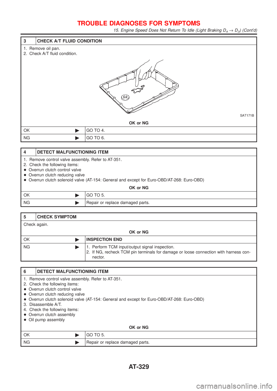
3 CHECK A/T FLUID CONDITION
1. Remove oil pan.
2. Check A/T fluid condition.
SAT171B
OK or NG
OK©GO TO 4.
NG©GO TO 6.
4 DETECT MALFUNCTIONING ITEM
1. Remove control valve assembly. Refer to AT-351.
2. Check the following items:
+Overrun clutch control valve
+Overrun clutch reducing valve
+Overrun clutch solenoid valve (AT-154: General and except for Euro-OBD/AT-268: Euro-OBD)
OK or NG
OK©GO TO 5.
NG©Repair or replace damaged parts.
5 CHECK SYMPTOM
Check again.
OK or NG
OK©INSPECTION END
NG©1. Perform TCM input/output signal inspection.
2. If NG, recheck TCM pin terminals for damage or loose connection with harness con-
nector.
6 DETECT MALFUNCTIONING ITEM
1. Remove control valve assembly. Refer to AT-351.
2. Check the following items:
+Overrun clutch control valve
+Overrun clutch reducing valve
+Overrun clutch solenoid valve (AT-154: General and except for Euro-OBD/AT-268: Euro-OBD)
3. Disassemble A/T.
4. Check the following items:
+Overrun clutch assembly
+Oil pump assembly
OK or NG
OK©GO TO 5.
NG©Repair or replace damaged parts.
TROUBLE DIAGNOSES FOR SYMPTOMS
15. Engine Speed Does Not Return To Idle (Light Braking D4®D3) (Cont'd)
AT-329
Page 336 of 2898

20. Vehicle Does Not Decelerate By Engine
Brake
=NJAT0350SYMPTOM:
Vehicle does not decelerate by engine brake when shifting
from 2
2(12)to11.
1 CHECK SYMPTOM
Is 6. Vehicle Does Not Creep Backward In ªRº Position OK?
YesorNo
Ye s©Go to 15. Engine Speed Does Not Return To Idle (Light Braking D
4®D3), AT-328.
No©Go to 6. Vehicle Does Not Creep Backward In ªRº Position, AT-305.
SAT088JA
SAT360H
SAT004K
21. TCM Self-diagnosis Does Not Activate (PNP,
Overdrive Control and Throttle Position
Switches Circuit Checks)
NJAT0351SYMPTOM:
O/D OFF indicator lamp does not come on in TCM self-diag-
nostic procedure even if the lamp circuit is good.
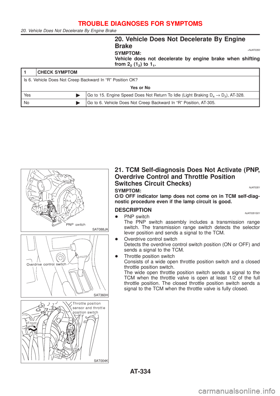
DESCRIPTIONNJAT0351S01+PNP switch
The PNP switch assembly includes a transmission range
switch. The transmission range switch detects the selector
lever position and sends a signal to the TCM.
+Overdrive control switch
Detects the overdrive control switch position (ON or OFF) and
sends a signal to the TCM.
+Throttle position switch
Consists of a wide open throttle position switch and a closed
throttle position switch.
The wide open throttle position switch sends a signal to the
TCM when the throttle valve is open at least 1/2 of the full
throttle position. The closed throttle position switch sends a
signal to the TCM when the throttle valve is fully closed.
TROUBLE DIAGNOSES FOR SYMPTOMS
20. Vehicle Does Not Decelerate By Engine Brake
AT-334
Page 358 of 2898
SAT058K
*1: With gusset to A/T
*2: With gusset to cylinder block
SAT638A
5. Reinstall any part removed.
6. Adjust control cable. Refer to AT-352.
7. Check continuity of PNP switch. Refer to AT-334.
8. Refill transaxle with ATF and check fluid level.
9. Move selector lever through all positions to be sure that tran-
saxle operates correctly. With parking brake applied, idle
engine. Move selector lever through ªNº to ªDº, to ª2º, to ª1º and
ªRº positions. A slight shock should be felt through the hand
gripping the selector each time the transaxle is shifted.
10. Perform road test. Refer to AT-85.
REMOVAL AND INSTALLATION
Installation (Cont'd)
AT-356
Page 379 of 2898
SAT705D
d. Remove idler gear and output gear using a puller.
SAT706DB
e. Remove reduction pinion gear and output shaft from transmis-
sion case.
f. Remove reduction pinion bearing adjusting shim from reduc-
tion pinion gear.
g. Remove adjusting spacer from output shaft.
SAT059D
3AX10 and 3AX18 models
42. Remove output shaft assembly according to the following pro-
cedures.
a. Remove side cover bolts.
SAT434D
b. Remove side cover by lightly tapping it with a soft hammer.
+Be careful not to drop output shaft assembly. It might
come out when removing side cover.
SAT440D
c. Remove adjusting shim.
DISASSEMBLY
AT-377
Page 396 of 2898
SAT873J
g. Install check balls, oil cooler relief valve springs and T/C pres-
sure holding spring in their proper positions in lower body.
SAT077F
h. Install lower separating gasket, inner separating gasket and
lower separating plate in order shown in the illustration.
SAT078F
i. Install boltsEfrom bottom of lower body. Using boltEas
guides, install separating plate and gaskets as a set.
j. Install support plates on lower body.
AAT536
k. Install lower body on inter body using reamer boltsFas guides
and tighten reamer boltsFslightly.
SAT317G
2. Install O-rings to solenoid valves and terminal body.
+Apply ATF to O-rings.
REPAIR FOR COMPONENT PARTS
Control Valve Assembly (Cont'd)
AT-394