Page 537 of 2898
InstallationNJBR0026CAUTION:
+Be careful not to deform or bend brake pipes, during
installation of booster.
+Replace clevis pin if damaged.
+Refill with new brake fluid ªDOT 3 or DOT 4º.
+Never reuse drained brake fluid.
+Take care not to damage brake booster mounting bolt
thread when installing. Due to the acute angle of
installation, the threads can be damaged with the dash
panel.
SBR237EA
1. Before fitting booster, temporarily adjust clevis to dimension
shown.
2. Fit booster, then secure mounting nuts (brake pedal bracket to
master cylinder) lightly.
3. Connect brake pedal and booster input rod with clevis pin.
4. Secure mounting nuts.
Specification:
13 - 16 N´m (1.3 - 1.6 kg-m,9-12ft-lb)
5. Install master cylinder. Refer to ªInstallationº in ªMASTER
CYLINDERº, BR-16, 19.
6. Bleed air. Refer to ªBleeding Brake Systemº, BR-9.
BRAKE BOOSTER
Installation
BR-21
Page 542 of 2898
lightly [approximately 9.8 N (1.0 kg, 2.2 lb)].
6. Remove thickness gauges (2).
+Leave sprocket retaining bolts (M6) until installation.
VACUUM PUMP
Assembly (Cont'd)
BR-26
Page 566 of 2898

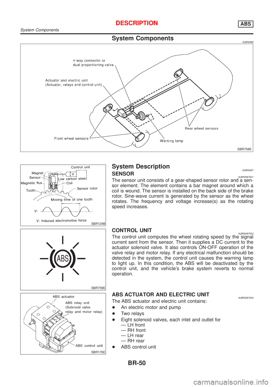
System ComponentsNJBR0086
SBR758E
SBR124B
System DescriptionNJBR0087SENSORNJBR0087S01The sensor unit consists of a gear-shaped sensor rotor and a sen-
sor element. The element contains a bar magnet around which a
coil is wound. The sensor is installed on the back side of the brake
rotor. Sine-wave current is generated by the sensor as the wheel
rotates. The frequency and voltage increase(s) as the rotating
speed increases.
SBR759E
CONTROL UNITNJBR0087S02The control unit computes the wheel rotating speed by the signal
current sent from the sensor. Then it supplies a DC current to the
actuator solenoid valve. It also controls ON-OFF operation of the
valve relay and motor relay. If any electrical malfunction should be
detected in the system, the control unit causes the warning lamp
to light up. In this condition, the ABS will be deactivated by the
control unit, and the vehicle's brake system reverts to normal
operation.
SBR176E
ABS ACTUATOR AND ELECTRIC UNITNJBR0087S03The ABS actuator and electric unit contains:
+An electric motor and pump
+Two relays
+Eight solenoid valves, each inlet and outlet for
Ð LH front
Ð RH front
Ð LH rear
Ð RH rear
+ABS control unit
DESCRIPTIONABS
System Components
BR-50
Page 718 of 2898

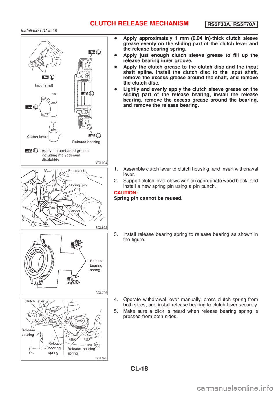
YCL004
+Apply approximately 1 mm (0.04 in)-thick clutch sleeve
grease evenly on the sliding part of the clutch lever and
the release bearing spring.
+Apply just enough clutch sleeve grease to fill up the
release bearing inner groove.
+Apply the clutch grease to the clutch disc and the input
shaft spline. Install the clutch disc to the input shaft,
remove the excess grease around the shaft, and remove
the clutch disc.
+Lightly and evenly apply the clutch sleeve grease on the
sliding part of the release bearing, install the release
bearing, remove the excess grease around the bearing,
and remove the release bearing.
SCL822
1. Assemble clutch lever to clutch housing, and insert withdrawal
lever.
2. Support clutch lever claws with an appropriate wood block, and
install a new spring pin using a pin punch.
CAUTION:
Spring pin cannot be reused.
SCL736
3. Install release bearing spring to release bearing as shown in
the figure.
SCL823
4. Operate withdrawal lever manually, press clutch spring from
both sides, and install release bearing to clutch lever securely.
5. Make sure a click is heard when release bearing spring is
pressed from both sides.
CLUTCH RELEASE MECHANISMRS5F30A, RS5F70A
Installation (Cont'd)
CL-18
Page 723 of 2898

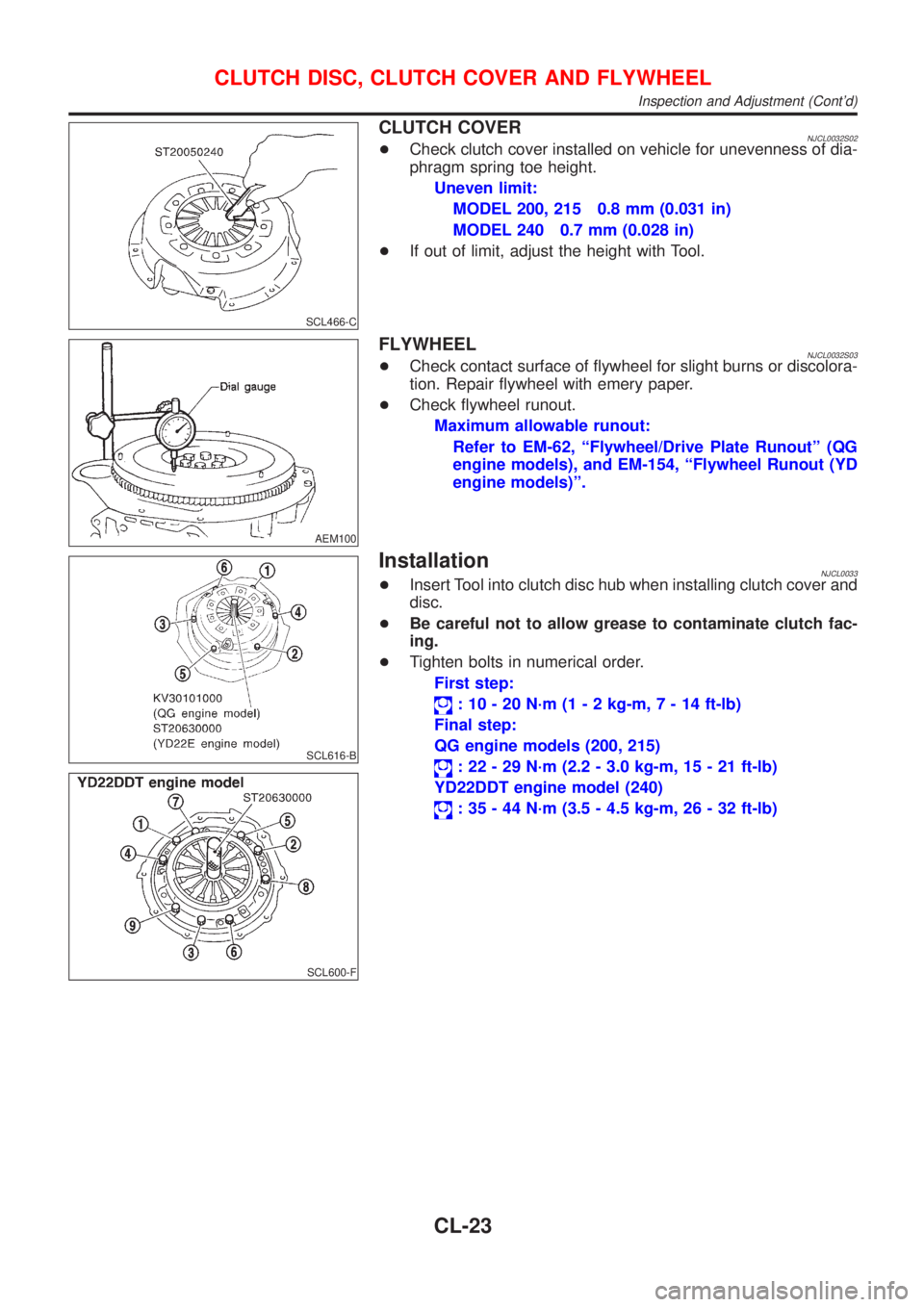
SCL466-C
CLUTCH COVERNJCL0032S02+Check clutch cover installed on vehicle for unevenness of dia-
phragm spring toe height.
Uneven limit:
MODEL 200, 215 0.8 mm (0.031 in)
MODEL 240 0.7 mm (0.028 in)
+If out of limit, adjust the height with Tool.
AEM100
FLYWHEELNJCL0032S03+Check contact surface of flywheel for slight burns or discolora-
tion. Repair flywheel with emery paper.
+Check flywheel runout.
Maximum allowable runout:
Refer to EM-62, ªFlywheel/Drive Plate Runoutº (QG
engine models), and EM-154, ªFlywheel Runout (YD
engine models)º.
SCL616-B
SCL600-F
InstallationNJCL0033+Insert Tool into clutch disc hub when installing clutch cover and
disc.
+Be careful not to allow grease to contaminate clutch fac-
ing.
+Tighten bolts in numerical order.
First step:
: 10 - 20 N´m (1 - 2 kg-m,7-14ft-lb)
Final step:
QG engine models (200, 215)
: 22 - 29 N´m (2.2 - 3.0 kg-m, 15 - 21 ft-lb)
YD22DDT engine model (240)
: 35 - 44 N´m (3.5 - 4.5 kg-m, 26 - 32 ft-lb)
CLUTCH DISC, CLUTCH COVER AND FLYWHEEL
Inspection and Adjustment (Cont'd)
CL-23
Page 740 of 2898

Supplemental Restraint System (SRS) ªAIR
BAGº and ªSEAT BELT PRE-TENSIONERº
NJEC0002The Supplemental Restraint System such as ªAIR BAGº and ªSEAT BELT PRE-TENSIONERº used along with
a seat belt, helps to reduce the risk or severity of injury to the driver and front passenger for certain types of
collision. The SRS system composition which is available to NISSAN MODEL N16 is as follows (The compo-
sition varies according to the destination and optional equipment.):
+For a frontal collision
The Supplemental Restraint System consists of driver air bag module (located in the center of the steer-
ing wheel), front passenger air bag module (located on the instrument panel on passenger side), front seat
belt pre-tensioners, a diagnoses sensor unit, warning lamp, wiring harness and spiral cable.
+For a side collision
The Supplemental Restraint System consists of front side air bag module (located in the outer side of front
seat), side air bag (satellite) sensor, diagnoses sensor unit (one of components of air bags for a frontal
collision), wiring harness, warning lamp (one of components of air bags for a frontal collision).
Information necessary to service the system safely is included in theRS sectionof this Service Manual.
WARNING:
+To avoid rendering the SRS inoperative, which could increase the risk of personal injury or death
in the event of a collision which would result in air bag inflation, all maintenance should be per-
formed by an authorized NISSAN dealer.
+Improper maintenance, including incorrect removal and installation of the SRS, can lead to per-
sonal injury caused by unintentional activation of the system. For removal of Spiral Cable and Air
Bag Module, see the RS section.
+Do not use electrical test equipment on any circuit related to the SRS unless instructed to in this
Service Manual. SRS wiring harness can be identified by yellow harness connector.
Precautions for On Board Diagnostic (OBD)
System of Engine and A/T
NJEC0003The ECM has an on board diagnostic system. It will light up the malfunction indicator (MI) to warn the driver
of a malfunction causing emission deterioration.
CAUTION:
+Be sure to turn the ignition switch ªOFFº and disconnect the negative battery terminal before any
repair or inspection work. The open/short circuit of related switches, sensors, solenoid valves, etc.
will cause the MI to light up.
+Be sure to connect and lock the connectors securely after work. A loose (unlocked) connector will
cause the MI to light up due to the open circuit. (Be sure the connector is free from water, grease,
dirt, bent terminals, etc.)
+Certain systems and components, especially those related to OBD, may use a new style slide-
locking type harness connector.
For description and how to disconnect, refer to EL section, ªDescriptionº, ªHARNESS CONNEC-
TORº.
+Be sure to route and secure the harnesses properly after work. The interference of the harness with
a bracket, etc. may cause the MI to light up due to the short circuit.
+Be sure to connect rubber tubes properly after work. A misconnected or disconnected rubber tube
may cause the MI to light up due to the malfunction of fuel injection system, etc.
+Be sure to erase the unnecessary malfunction information (repairs completed) from the ECM and
TCM (Transmission Control Module) before returning the vehicle to the customer.
PRECAUTIONSQG
Supplemental Restraint System (SRS) ªAIR BAGº and ªSEAT BELT PRE-TENSIONERº
EC-16
Page 741 of 2898

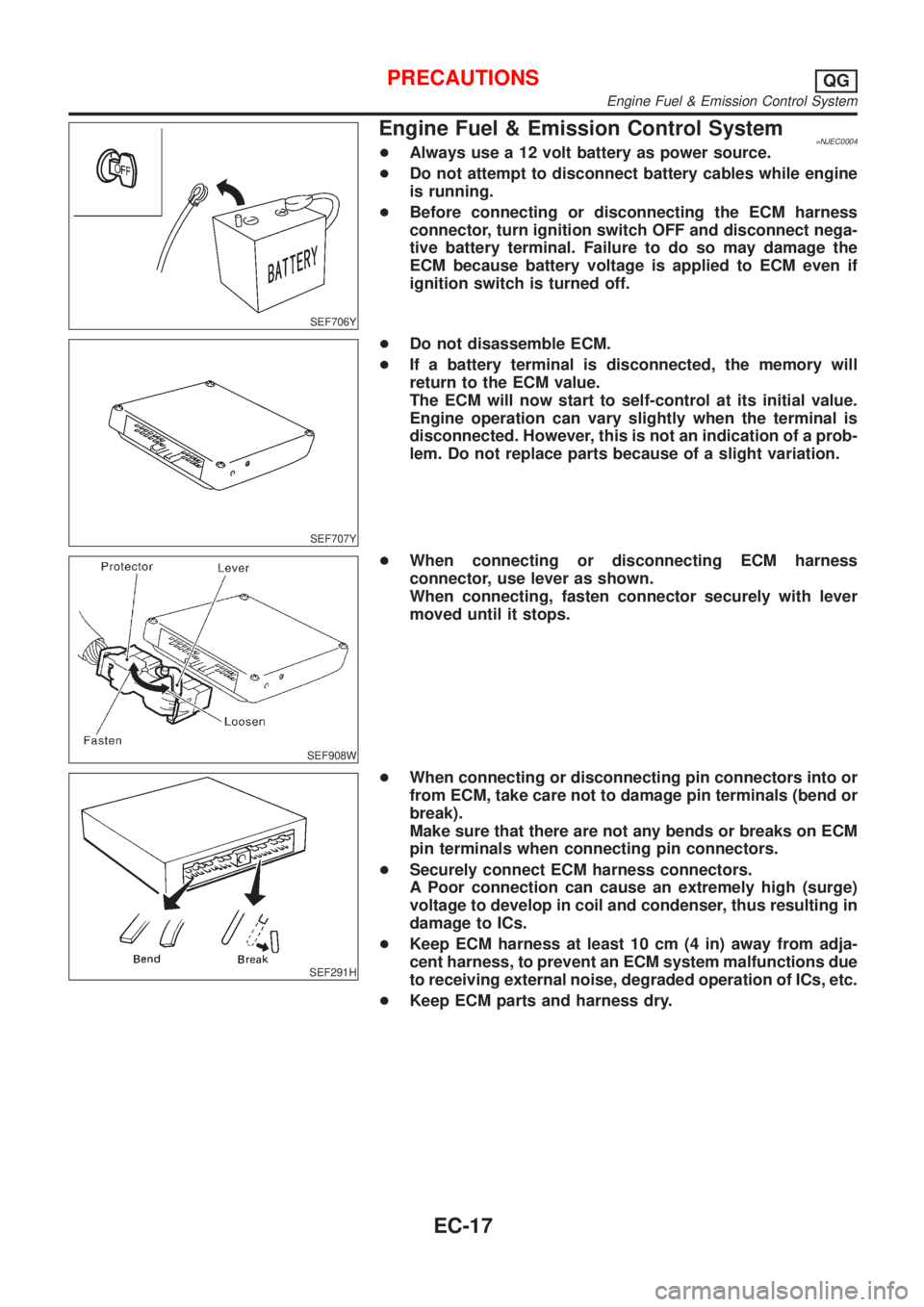
SEF706Y
Engine Fuel & Emission Control System=NJEC0004+Always use a 12 volt battery as power source.
+Do not attempt to disconnect battery cables while engine
is running.
+Before connecting or disconnecting the ECM harness
connector, turn ignition switch OFF and disconnect nega-
tive battery terminal. Failure to do so may damage the
ECM because battery voltage is applied to ECM even if
ignition switch is turned off.
SEF707Y
+Do not disassemble ECM.
+If a battery terminal is disconnected, the memory will
return to the ECM value.
The ECM will now start to self-control at its initial value.
Engine operation can vary slightly when the terminal is
disconnected. However, this is not an indication of a prob-
lem. Do not replace parts because of a slight variation.
SEF908W
+When connecting or disconnecting ECM harness
connector, use lever as shown.
When connecting, fasten connector securely with lever
moved until it stops.
SEF291H
+When connecting or disconnecting pin connectors into or
from ECM, take care not to damage pin terminals (bend or
break).
Make sure that there are not any bends or breaks on ECM
pin terminals when connecting pin connectors.
+Securely connect ECM harness connectors.
A Poor connection can cause an extremely high (surge)
voltage to develop in coil and condenser, thus resulting in
damage to ICs.
+Keep ECM harness at least 10 cm (4 in) away from adja-
cent harness, to prevent an ECM system malfunctions due
to receiving external noise, degraded operation of ICs, etc.
+Keep ECM parts and harness dry.
PRECAUTIONSQG
Engine Fuel & Emission Control System
EC-17
Page 742 of 2898

MEF040D
+Handle mass air flow sensor carefully to avoid damage.
+Do not disassemble mass air flow sensor.
+Do not clean mass air flow sensor with any type of deter-
gent.
+Do not disassemble IAC valve-AAC valve.
+Even a slight leak in the air intake system can cause seri-
ous problems.
+Do not shock or jar the camshaft position sensor and
crankshaft position sensor.
+Before replacing ECM, perform refer to ªECM Terminals
and Reference Valueº inspection and make sure ECM
functions properly, EC-164.
SAT652J
+After performing each TROUBLE DIAGNOSIS, perform
ªDTC Confirmation Procedureº or ªOverall Function
Checkº.
The DTC should not be displayed in the ªDTC Confirma-
tion Procedureº if the repair is completed. The ªOverall
Function Checkº should be a good result if the repair is
completed.
SEF348N
+When measuring ECM signals with a circuit tester, never
allow the two tester probes to contact.
Accidental contact of probes will cause a short circuit and
damage the ECM power transistor.
+Do not use ECM ground terminals when measuring input/
output voltage. Doing so may result in damage to the
ECM's transistor. Use a ground other than ECM terminals,
such as the ground.
PRECAUTIONSQG
Engine Fuel & Emission Control System (Cont'd)
EC-18