Page 551 of 2898
ComponentNJBR0038
SBR753E
1. Cable guide
2. Cylinder
3. Toggle lever
4. Pin
5. Pin boot
6. Torque member
7. Inner shim
8. Inner pad
9. Pad retainer
10. Outer pad11. Outer shim
12. Strut
13. O-ring
14. Push rod
15. Key plate
16. Retaining washer
17. Spring
18. Spring cover
19. Snap ring B
20. Piston seal21. Snap ring A
22. Washer
23. Wave washer
24. Washer
25. Bearing
26. Adjuster
27. Cup
28. Piston
29. Piston boot
Pad ReplacementNJBR0037WARNING:
Clean brake pads with a vacuum dust collector to minimize the
hazard of airborne particles or other materials.
CAUTION:
+When cylinder body is open, do not depress brake pedal
because piston will pop out.
+Be careful not to damage piston boot or get oil on rotor.
Always replace shims in replacing pads.
+If shims are rusted or show peeling of rubber coat, replace
them with new shims.
REAR DISC BRAKE (CAM & STRUT TYPE)
Component
BR-35
Page 554 of 2898

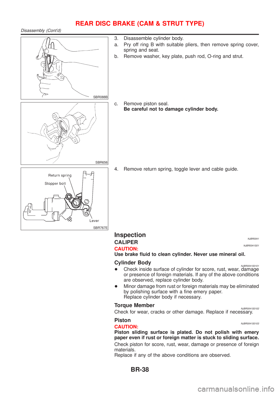
SBR088B
3. Disassemble cylinder body.
a. Pry off ring B with suitable pliers, then remove spring cover,
spring and seat.
b. Remove washer, key plate, push rod, O-ring and strut.
SBR656
c. Remove piston seal.
Be careful not to damage cylinder body.
SBR767E
4. Remove return spring, toggle lever and cable guide.
InspectionNJBR0041CALIPERNJBR0041S01CAUTION:
Use brake fluid to clean cylinder. Never use mineral oil.
Cylinder BodyNJBR0041S0101+Check inside surface of cylinder for score, rust, wear, damage
or presence of foreign materials. If any of the above conditions
are observed, replace cylinder body.
+Minor damage from rust or foreign materials may be eliminated
by polishing surface with a fine emery paper.
Replace cylinder body if necessary.
Torque MemberNJBR0041S0102Check for wear, cracks or other damage. Replace if necessary.
PistonNJBR0041S0103CAUTION:
Piston sliding surface is plated. Do not polish with emery
paper even if rust or foreign matter is stuck to sliding surface.
Check piston for score, rust, wear, damage or presence of foreign
materials.
Replace if any of the above conditions are observed.
REAR DISC BRAKE (CAM & STRUT TYPE)
Disassembly (Cont'd)
BR-38
Page 556 of 2898
SBR248B
2. Generously apply rubber grease to strut and push rod to make
insertion easy.
SBR893
3. Fit push rod into square hole in key plate. Also match convex
portion of key plate with concave portion of cylinder.
SBR754E
4. Install rod, push rod and key plate.
SBR869CB
SBR879-B
5. Install seat, spring, spring cover and ring B with suitable press
and drift.
REAR DISC BRAKE (CAM & STRUT TYPE)
Assembly (Cont'd)
BR-40
Page 585 of 2898
PBR455D
ACTIVE TEST PROCEDURENJBR0093S04+When conducting Active test, vehicle must be stationary.
+When ABS warning lamp stays on, never conduct Active test.
1. Turn ignition switch OFF.
2. Connect CONSULT-II to data link connector.
3. Start engine.
4. Touch ªSTARTº on CONSULT-II screen.
PBR385C
5. Touch ªABSº.
PST412B
6. Touch ªACTIVE TESTº.
PBR976C
7. Select active test item by touching screen.
PBR934C
8. Touch ªSTARTº.
9. Carry out the active test by touching screen key.
ON BOARD DIAGNOSTIC SYSTEM DESCRIPTIONABS
CONSULT-II Inspection Procedure (Cont'd)
BR-69
Page 639 of 2898
Front Door LockNJBT0010
SBT053A
+For removal of front door finisher, refer to ªDOOR TRIMº,
BT-39.
+Remove sealing screen.
SBT977
BELL CRANK ADJUSTMENTNJBT0010S01CAUTION:
Before adjusting bell crank, make sure that rod is installed to
inside handle.
After installing door lock and inside handle, set them in the lock
position. Using a flat-bladed screwdriver, expand rod holder.
Remove rod free play at joining area and set rod in position.
After adjusting bell crank adjustments have been made, operate
door lock knob, door lock switch and door key to make sure that
they lock and unlock properly.
SBT978
OUTSIDE HANDLE ROD ADJUSTMENTNJBT0010S02Rotate rod holder so that rod-to-holder clearance is adjusted as
shown in the figure at left.
CAUTION:
Make sure that rod-to-holder clearance is not ª0º mm (0 in),
and that rod is not held pressed.
DOOR
Front Door Lock
BT-21
Page 640 of 2898
SBT979
REMOVALNJBT0010S03+For removal of front door finisher, refer to ªDOOR TRIMº,
BT-39.
+Remove sealing screen.
+For removal of front door glass, refer to ªFront Door Glassº,
BT-17.
1. Remove lower rear sash (unitized with glass run) securing
bolts. Remove lower rear sash from door panel and away from
door lock.
SBT980
2. Remove inside handle escutcheon A.
3. Remove screw securing inside handle.
4. Detach bell crank at lock knob joining area.
5. Detach inside handle rod on the door lock assembly side.
6. Slide inside handle backward and remove inside handle.
7. Remove rod from inside handle.
SBT981
8. Detach key lock rod and outside handle rod at joining area (on
the outside handle side).
9. Disconnect door lock actuator connector.
10. Remove screws securing door lock assembly, then remove
door lock assembly.
11. Remove bolts securing outside handle, then remove outside
handle assembly.
DOOR
Front Door Lock (Cont'd)
BT-22
Page 773 of 2898

7 PERFORM IDLE AIR VOLUME LEARNING
Refer to ªIdle Air Volume Learningº, EC-57.
Which is the result CMPLT or INCMP?
CMPLT or INCMP
CMPLT©GO TO 8.
INCMP©1. Follow the construction of ªIdle Air Volume Learningº.
2. GO TO 4.
8 CHECK TARGET IDLE SPEED AGAIN
With CONSULT-II
1. Start engine and warm it up to normal operating temperature.
2. Select ªENG SPEEDº in ªDATA MONITORº mode with CONSULT-II.
3. Check idle speed.
M/T: 700±50 rpm
A/T: 800±50 rpm (in ªPº or ªNº position)
Without CONSULT-II
1. Start engine and warm it up to normal operating temperature.
2. Check idle speed.
M/T: 700±50 rpm
A/T: 800±50 rpm (in ªPº or ªNº position)
OK or NG
OK©GO TO 10.
NG©GO TO 9.
9 CHECK ECM FUNCTION
1. Substitute another known-good ECM to check ECM function. (ECM may be the cause of a problem, but this is rarely
the case.)
2. Perform initialization of NATS system and registration of NATS ignition key IDs. Refer to ªNATS (Nissan Anti-Theft
System)º, EC-74.
©GO TO 4.
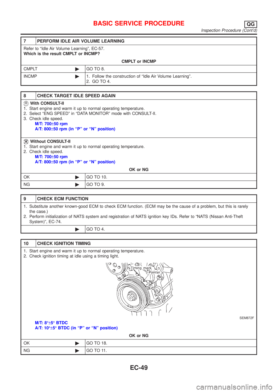
10 CHECK IGNITION TIMING
1. Start engine and warm it up to normal operating temperature.
2. Check ignition timing at idle using a timing light.
SEM872F
M/T: 8ɱ5É BTDC
A/T: 10ɱ5É BTDC (in ªPº or ªNº position)
OK or NG
OK©GO TO 18.
NG©GO TO 11.
BASIC SERVICE PROCEDUREQG
Inspection Procedure (Cont'd)
EC-49
Page 775 of 2898
15 CHECK ECM FUNCTION
1. Substitute another known-good ECM to check ECM function.
(ECM may be the cause of a problem, but this is rarely the case.)
2. Perform initialization of NATS system and registration of NATS ignition key IDs. Refer to ªNATS (Nissan Anti-Theft
System)º, EC-74.
©GO TO 13.
16 CHECK IGNITION TIMING AGAIN
Check ignition timing again. Refer to Test No. 12.
OK or NG
OK©GO TO 18.
NG©GO TO 17.
17 CHECK TIMING CHAIN INSTALLATION
Check timing chain installation. Refer to EM-28, ªInstallationº.
OK or NG
OK©GO TO 15.
NG©1. Repair the timing chain installation.
2. GO TO 13.
18 ERASE UNNECESSARY DTC
After this inspection, unnecessary DTC No. might be displayed.
Erase the stored memory in ECM and TCM (Transmission control module).
Refer to ªHOW TO ERASE EMISSION-RELATED DIAGNOSTIC INFORMATIONº, EC-70 or EC-73 and AT-52, ªHOW TO
ERASE DTCº.
With CONSULT-II©GO TO 19.
Without CONSULT-II©GO TO 20.
BASIC SERVICE PROCEDUREQG
Inspection Procedure (Cont'd)
EC-51