Page 621 of 2898
Service NoticeNJBT0001+When removing or installing various parts, place a cloth or padding onto the vehicle body to prevent
scratches.
+Handle trim, molding, instruments, grille, etc. carefully during removing or installing. Be careful not to oil
or damage them.
+Apply sealing compound where necessary when installing parts.
+When applying sealing compound, be careful that the sealing compound does not protrude from parts.
+When replacing any metal parts (for example body outer panel, members, etc.), be sure to take rust pre-
vention measures.
Supplemental Restraint System (SRS) ªAIR
BAGº and ªSEAT BELT PRE-TENSIONERº
NJBT0002The Supplemental Restraint System such as ªAIR BAGº and ªSEAT BELT PRE-TENSIONERº used along with
a seat belt, helps to reduce the risk or severity of injury to the driver and front passenger for certain types of
collision. The SRS system composition which is available to NISSAN MODEL N16 is as follows (The compo-
sition varies according to the destination and optional equipment.):
+For a frontal collision
The Supplemental Restraint System consists of driver air bag module (located in the center of the steer-
ing wheel), front passenger air bag module (located on the instrument panel on passenger side), front seat
belt pre-tensioners, a diagnosis sensor unit, warning lamp, wiring harness and spiral cable.
+For a side collision
The Supplemental Restraint System consists of front side air bag module (located in the outer side of front
seat), side air bag (satellite) sensor, diagnosis sensor unit (one of components of air bags for a frontal
collision), wiring harness, warning lamp (one of components of air bags for a frontal collision).
Information necessary to service the system safely is included in theRS sectionof this Service Manual.
WARNING:
+To avoid rendering the SRS inoperative, which could increase the risk of personal injury or death
in the event of a collision which would result in air bag inflation, all maintenance should be per-
formed by an authorized NISSAN dealer.
+Improper maintenance, including incorrect removal and installation of the SRS, can lead to per-
sonal injury caused by unintentional activation of the system. For removal of Spiral Cable and Air
Bag Module, see the RS section.
+Do not use electrical test equipment on any circuit related to the SRS unless instructed to in this
Service Manual. SRS wiring harnesses can be identified by yellow harness connector.
PRECAUTIONS
Service Notice
BT-3
Page 625 of 2898

Removal and InstallationNJBT0004+When removing or installing hood, place a cloth or other padding on hood. This prevents vehicle body from
being scratched.
+Bumper fascia is made of plastic. Do not use excessive force and be sure to keep oil away from it.
+Hood adjustment: Adjust at hinge portion.
+Hood lock adjustment: After adjusting, check hood lock control operation. Apply a coat of grease to hood
locks engaging mechanism.
+Hood opener: Do not attempt to bend cable forcibly. Doing so increases effort required to unlock hood.
FRONT BUMPER ASSEMBLYNJBT0004S011. Remove clips securing front grille, then remove front grille.
2. Remove front turn signal lamp, then disconnect harness connectors.
3. Remove clips and screws securing left and right sides of fender protectors.
4. Remove clips and screws securing left and right sides of fender protectors in wheelhoulse.
5. Remove screws securing left and right front fenders to bumper fascia.
6. Remove screws securing left and right radiator core support side to bumper fascia.
7. Remove bolts securing radiator core support lower to bumper fascia.
8. Remove clips securing radiator core support upper to bumper fascia.
9. Extract bumper fascia assembly. Then disconnect harness connectors. (Models with fog lamp assembly)
10. Remove energy absorber. (Where fitted)
11. Remove bolts and hooks securing the headlamp assembly, then disconnect harness connectors.
12. Remove nuts securing bumper reinforcement to left and right bumper stays.(Where fitted)
13. Extract bumper reinforcement. (Where fitted)
14. Remove bolts securing bumper upper retainer, then remove bumper upper retainer.
15. Remove bolts securing bumper stays, then remove the bumper stays.
Fog lamp assembly (Models with fog lamp assembly)
16. Remove bolt securing fog lamp assembly.
17. Extract fog lamp assembly.
NBT182
BODY FRONT END
Removal and Installation
BT-7
Page 628 of 2898
Removal and Installation (Sedan)NJBT0005+When removing or installing trunk lid, place a cloth or other padding on trunk lid. This prevents vehicle
body from being scratched.
+Bumper fascia is made of plastic. Do not use excessive force and be sure to keep oil away from it.
+Trunk lid adjustment: Adjust at hinge-trunk lid portion for proper trunk lid fit.
+Trunk lid lock system adjustment: Adjust striker so that it is in the center of the lock. After adjustment, check
trunk lid lock operation.
+After installation, make sure that trunk lid and fuel filler lid open smoothly.
HFor Wiring Diagram, refer to EL-297, ªTRUNK LID OPENERº.
REAR BUMPER ASSEMBLYNJBT0005S011. Remove clips and screws securing left and right chipping protectors.
2. Remove screws securing left and right rear fenders to bumper fascia.
3. Remove bolts securing bumper fascia assembly.
4. Remove clips securing bumper fascia assembly.
5. Open the bumper fascia side outward to disengage from side clips.
6. Extract bumper fascia assembly.
7. Remove bolts securing bumper stays, then remove the bumper stays.
BODY REAR END AND OPENER
Removal and Installation (Sedan)
BT-10
Page 631 of 2898
Removal and Installation (Hatchback)NJBT0034+When removing or installing back door, place a cloth or other padding on back door. This prevents vehicle
body from being scratched.
+Bumper fascia is made of plastic. Do not use excessive force and be sure to keep oil away from it.
+Back door adjustment: Adjust at hinge-back door portion for proper back door fit.
+Back door lock system adjustment: Adjust striker so that it is in the center of the lock. After adjustment,
check back door lock operation.
+After installation, make sure that back door and fuel filler lid open smoothly.
HFor Wiring Diagram, refer to EL-297, ªTRUNK LID OPENERº.
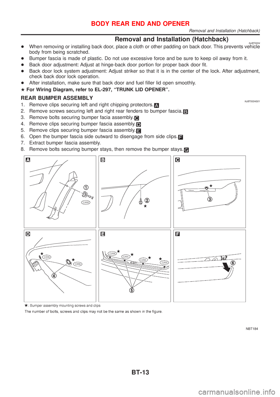
REAR BUMPER ASSEMBLYNJBT0034S011. Remove clips securing left and right chipping protectors.
2. Remove screws securing left and right rear fenders to bumper fascia.
3. Remove bolts securing bumper facia assembly.
4. Remove clips securing bumper fascia assembly.
5. Remove clips securing bumper fascia assembly.
6. Open the bumper fascia side outward to disengage from side clips.
7. Extract bumper fascia assembly.
8. Remove bolts securing bumper stays, then remove the bumper stays.
NBT184
BODY REAR END AND OPENER
Removal and Installation (Hatchback)
BT-13
Page 649 of 2898
Removal and InstallationNJBT0013SEDANNJBT0013S01CAUTION:
+Wrap the tip of flat-bladed screwdriver with a cloth when removing metal clips from garnishes.
1. Remove front and rear seats. Refer to ªFRONT SEATº and ªREAR SEATº for details, BT-56 and BT-60.
2. Remove front and rear seat belts. Refer to RS-5 and RS-11, ªFront Seat Beltº and ªRear Seat Beltº for
details.
3. Remove front and rear outer kicking plates.
4. Remove front and rear inner kicking plates.
5. Remove dash side finishers.
6. Remove front and rear body side welts.
7. Remove front pillar garnishes.
8. Remove center pillar lower garnishes.
9. Remove center pillar upper garnishes.
10. Remove rear seat back finishers.
11. Remove rear pillar finishers.
12. Remove high-mounted stop lamp. (Models without rear air spoiler)
13. Remove seat back center and side finishers. (For Europe)
14. Remove rear parcel shelf finisher.
15. Remove hoot rest.
16. Remove floor carpet.
SIDE AND FLOOR TRIM
Removal and Installation
BT-31
Page 702 of 2898
SBR820BA
PrecautionsNJCL0001+Recommended fluid is brake fluid ªDOT 4º. Refer to
MA-16, ªFluid and Lubricantsº.
+Never reuse drained brake fluid.
+Be careful not to splash brake fluid on painted areas.
+When removing and installing clutch piping, use Tool.
+Use new brake fluid to clean or wash all parts of master
cylinder and operating cylinder.
+Never use mineral oils such as gasoline or kerosene. It will
ruin the rubber parts of the hydraulic system.
WARNING:
After cleaning clutch disc, wipe it with a dust collector. Do not
use compressed air.
PRECAUTIONS
Precautions
CL-2
Page 704 of 2898
NJCL0004
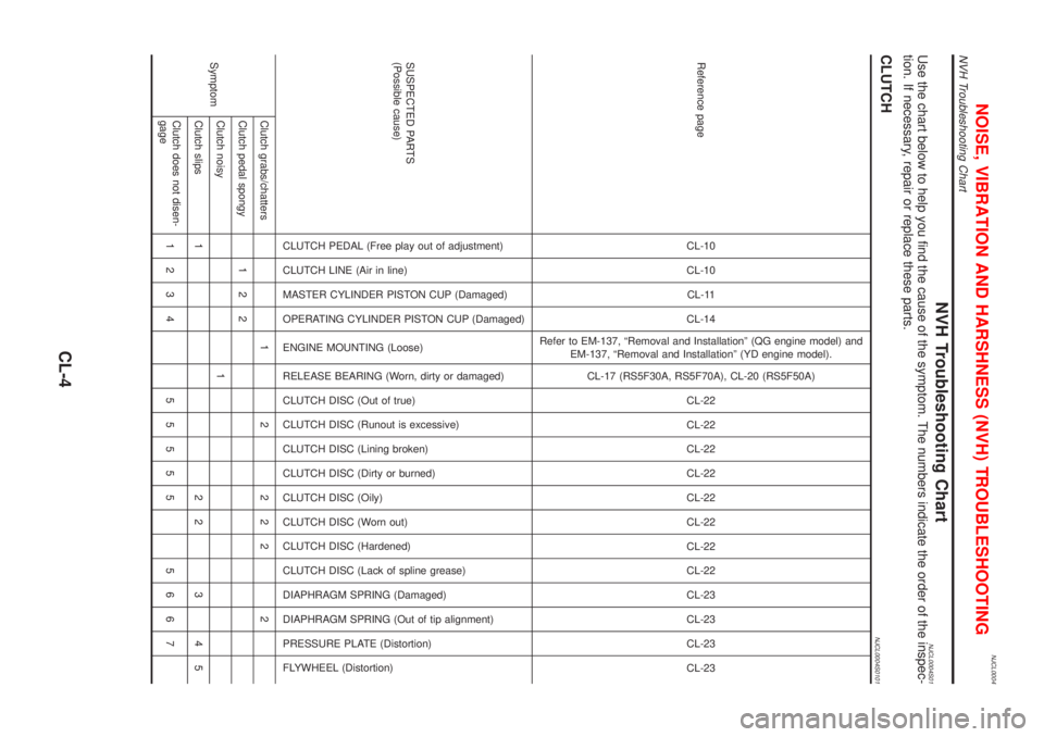
NVH Troubleshooting ChartNJCL0004S01Use the chart below to help you find the cause of the symptom. The numbers indicate the order of the inspec-
tion. If necessary, repair or replace these parts.
CLUTCHNJCL0004S0101
Reference pageCL-10
CL-10
CL-11
CL-14
Refer to EM-137, ªRemoval and Installationº (QG engine model) and
EM-137, ªRemoval and Installationº (YD engine model).
CL-17 (RS5F30A, RS5F70A), CL-20 (RS5F50A)
CL-22
CL-22
CL-22
CL-22
CL-22
CL-22
CL-22
CL-22
CL-23
CL-23
CL-23
CL-23
SUSPECTED PARTS
(Possible cause)
CLUTCH PEDAL (Free play out of adjustment)
CLUTCH LINE (Air in line)
MASTER CYLINDER PISTON CUP (Damaged)
OPERATING CYLINDER PISTON CUP (Damaged)
ENGINE MOUNTING (Loose)
RELEASE BEARING (Worn, dirty or damaged)
CLUTCH DISC (Out of true)
CLUTCH DISC (Runout is excessive)
CLUTCH DISC (Lining broken)
CLUTCH DISC (Dirty or burned)
CLUTCH DISC (Oily)
CLUTCH DISC (Worn out)
CLUTCH DISC (Hardened)
CLUTCH DISC (Lack of spline grease)
DIAPHRAGM SPRING (Damaged)
DIAPHRAGM SPRING (Out of tip alignment)
PRESSURE PLATE (Distortion)
FLYWHEEL (Distortion)
SymptomClutch grabs/chatters 1 2 2 2 2 2
Clutch pedal spongy 1 2 2
Clutch noisy 1
Clutch slips 1 2 2 3 4 5
Clutch does not disen-
gage1234 55555 5667
NOISE, VIBRATION AND HARSHNESS (NVH) TROUBLESHOOTING
NVH Troubleshooting Chart
CL-4
Page 717 of 2898
ComponentsNJCL0044
SCL819
SCL820
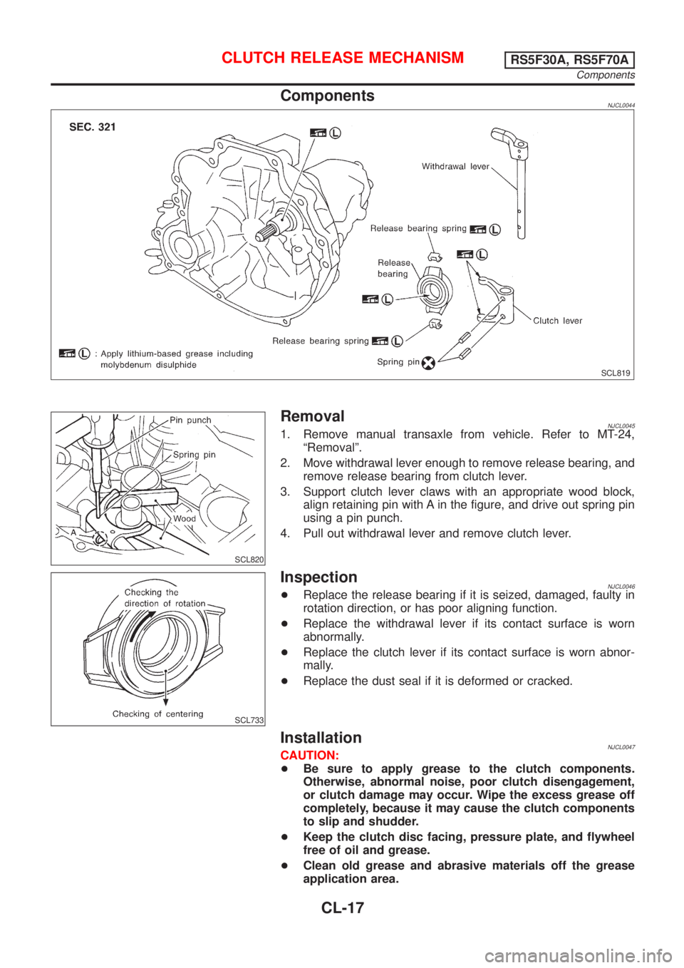
RemovalNJCL00451. Remove manual transaxle from vehicle. Refer to MT-24,
ªRemovalº.
2. Move withdrawal lever enough to remove release bearing, and
remove release bearing from clutch lever.
3. Support clutch lever claws with an appropriate wood block,
align retaining pin with A in the figure, and drive out spring pin
using a pin punch.
4. Pull out withdrawal lever and remove clutch lever.
SCL733
InspectionNJCL0046+Replace the release bearing if it is seized, damaged, faulty in
rotation direction, or has poor aligning function.
+Replace the withdrawal lever if its contact surface is worn
abnormally.
+Replace the clutch lever if its contact surface is worn abnor-
mally.
+Replace the dust seal if it is deformed or cracked.
InstallationNJCL0047CAUTION:
+Be sure to apply grease to the clutch components.
Otherwise, abnormal noise, poor clutch disengagement,
or clutch damage may occur. Wipe the excess grease off
completely, because it may cause the clutch components
to slip and shudder.
+Keep the clutch disc facing, pressure plate, and flywheel
free of oil and grease.
+Clean old grease and abrasive materials off the grease
application area.
CLUTCH RELEASE MECHANISMRS5F30A, RS5F70A
Components
CL-17