2001 NISSAN ALMERA engine
[x] Cancel search: enginePage 2830 of 2898
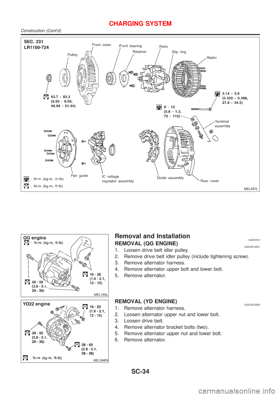
MEL497L
MEL145L
Removal and InstallationNJSC0013REMOVAL (QG ENGINE)NJSC0013S011. Loosen drive belt idler pulley.
2. Remove drive belt idler pulley (include tightening screw).
3. Remove alternator harness.
4. Remove alternator upper bolt and lower bolt.
5. Remove alternator.
MEL948N
REMOVAL (YD ENGINE)NJSC0013S031. Remove alternator harness.
2. Loosen alternator upper nut and lower bolt.
3. Loosen drive belt.
4. Remove alternator bracket bolts (two).
5. Remove alternator upper nut and lower bolt.
6. Remove alternator.
CHARGING SYSTEM
Construction (Cont'd)
SC-34
Page 2834 of 2898
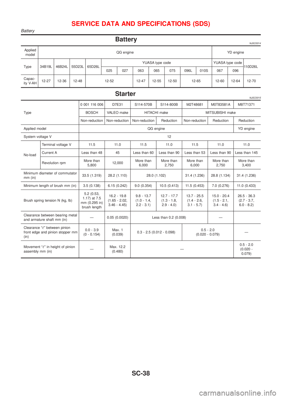
BatteryNJSC0014
Applied
modelQG engine YD engine
Type 34B19L 46B24L 55D23L 65D26LYUASA type code YUASA type code
110D26L
025 027 063 065 075 096L 010S 067 096
Capac-
ity V-AH12-27 12-36 12-48 12-52 12-47 12-55 12-50 12-65 12-60 12-64 12-70
StarterNJSC0015
Type0 001 116 006 D7E31 S114-570B S114-800B M2T48681 M0T83581A M8T71371
BOSCH VALEO make HITACHI make MITSUBISHI make
Non-reduction Non-reduction Non-reduction Reduction Non-reduction Reduction Reduction
Applied model QG engine YD engine
System voltage V12
No-loadTerminal voltage V 11.5 11.0 11.5 11.0 11.5 11.0 11.0
Current A Less than 48 45 Less than 60 Less than 90 Less than 53 Less than 90 Less than 145
Revolution rpmMore than
5,80012,000More than
6,000More than
2,750More than
6,000More than
2,750More than
3,400
Minimum diameter of commutator
mm (in)33.5 (1.319) 28.2 (1.110) 28.0 (1.102) 31.4 (1.236) 28.8 (1.134) 31.4 (1.236)
Minimum length of brush mm (in) 3.5 (0.138) 6.15 (0.242) 9.0 (0.354) 10.5 (0.413) 11.5 (0.453) 7.0 (0.276) 11.0 (0.433)
Brush spring tension N (kg, lb)5.2 (0.53,
1.17) at 7.5
mm (0.295 in)
brush length16.2 - 19.8
(1.65 - 2.02,
3.46 - 4.45)9.8 - 13.7
(1.0 - 1.4,
2.2 - 3.1)12.7 - 17.7
(1.3 - 1.8,
2.9 - 4.0)13.7 - 25.5
(1.4 - 2.6,
3.1 - 5.7)15.0 - 20.4
(1.5 - 2.1,
3.4 - 4.6)26.5 - 36.3
(2.7 - 3.7,
6.0 - 8.2)
Clearance between bearing metal
and armature shaft mm (in)Ð 0.05 (0.0020) Less than 0.2 (0.008) Ð
Clearance ª!º between pinion
front edge and pinion stopper mm
(in)0.0 - 3.9
(0 - 0.154)Max. 1
(0.039)0.3 - 2.5 (0.012 - 0.098)0.5 - 2.0
(0.020 - 0.079)Ð
Movement ª!º in height of pinion
assembly mm (in)ÐMax. 12.2
(0.480)Ð0.5 - 2.0
(0.020 -
0.079)
SERVICE DATA AND SPECIFICATIONS (SDS)
Battery
SC-38
Page 2835 of 2898
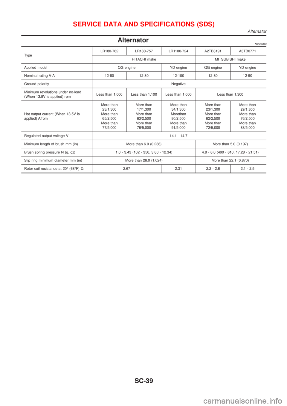
AlternatorNJSC0016
TypeLR180-762 LR180-757 LR1100-724 A2TB3191 A3TB0771
HITACHI make MITSUBISHI make
Applied model QG engine YD engine QG engine YD engine
Nominal rating V-A 12-80 12-80 12-100 12-80 12-90
Ground polarityNegative
Minimum revolutions under no-load
(When 13.5V is applied) rpmLess than 1,000 Less than 1,100 Less than 1,000 Less than 1,300
Hot output current (When 13.5V is
applied) A/rpmMore than
23/1,300
More than
65/2,500
More than
77/5,000More than
17/1,300
More than
63/2,500
More than
76/5,000More than
34/1,300
Morethan
80/2,500
More than
91/5,000More than
23/1,300
More than
62/2,500
More than
72/5,000More than
29/1,300
More than
76/2,500
More than
88/5,000
Regulated output voltage V 14.1 - 14.7
Minimum length of brush mm (in) More than 6.0 (0.236) More than 5.0 (0.197)
Brush spring pressure N (g, oz) 1.0 - 3.43 (102 - 350, 3.60 - 12.34) 4.8 - 6.0 (490 - 610, 17.28 - 21.51)
Slip ring minimum diameter mm (in) More than 26.0 (1.024) More than 22.1 (0.870)
Rotor coil resistance at 20É (68ÉF)W2.67 2.31 2.2 - 2.6 2.1 - 2.5
SERVICE DATA AND SPECIFICATIONS (SDS)
Alternator
SC-39
Page 2837 of 2898
STEERING SYSTEM
SECTION
ST
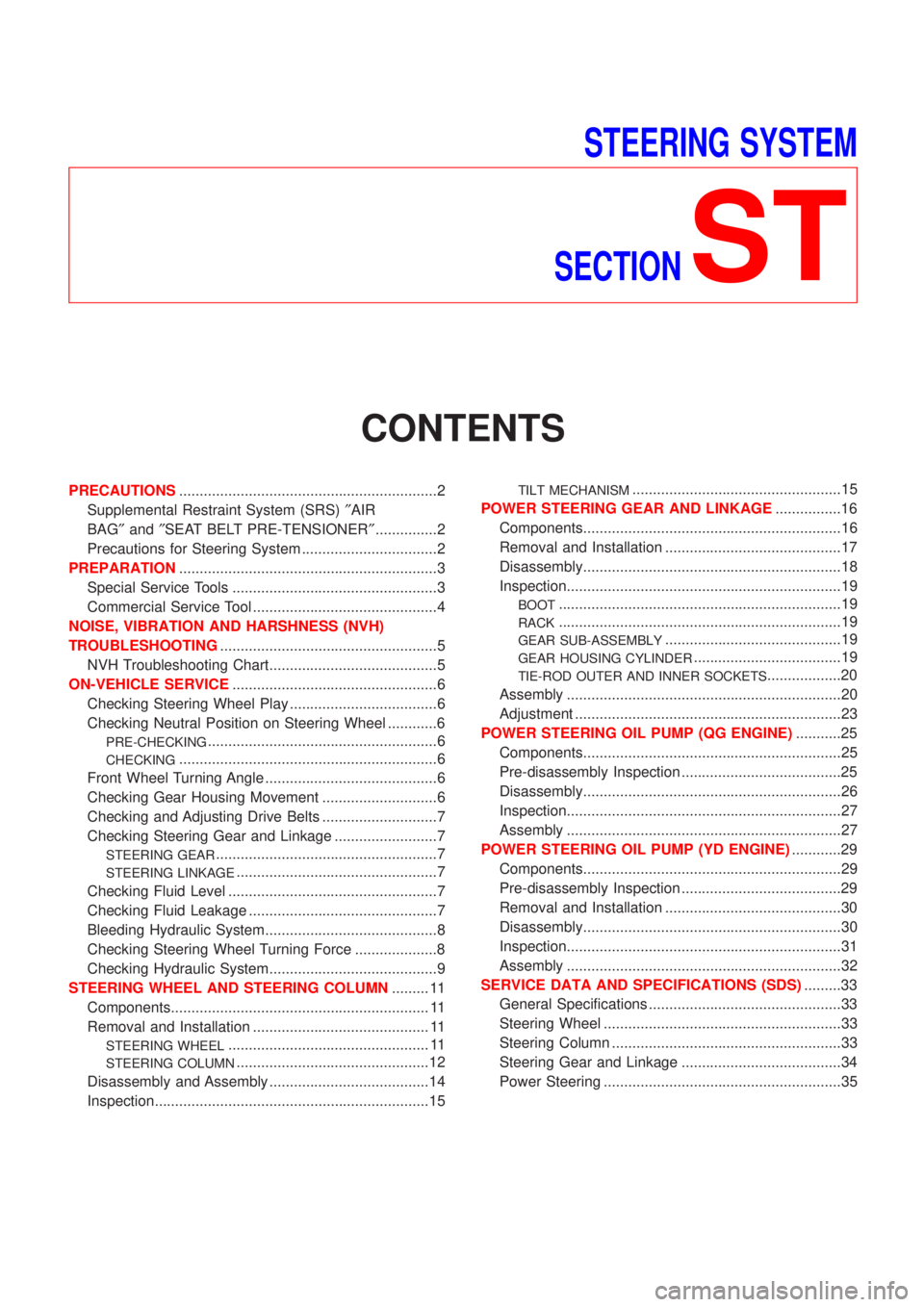
CONTENTS
PRECAUTIONS...............................................................2
Supplemental Restraint System (SRS)²AIR
BAG²and²SEAT BELT PRE-TENSIONER²...............2
Precautions for Steering System .................................2
PREPARATION...............................................................3
Special Service Tools ..................................................3
Commercial Service Tool .............................................4
NOISE, VIBRATION AND HARSHNESS (NVH)
TROUBLESHOOTING.....................................................5
NVH Troubleshooting Chart.........................................5
ON-VEHICLE SERVICE..................................................6
Checking Steering Wheel Play ....................................6
Checking Neutral Position on Steering Wheel ............6
PRE-CHECKING........................................................6
CHECKING...............................................................6
Front Wheel Turning Angle ..........................................6
Checking Gear Housing Movement ............................6
Checking and Adjusting Drive Belts ............................7
Checking Steering Gear and Linkage .........................7
STEERING GEAR......................................................7
STEERING LINKAGE.................................................7
Checking Fluid Level ...................................................7
Checking Fluid Leakage ..............................................7
Bleeding Hydraulic System..........................................8
Checking Steering Wheel Turning Force ....................8
Checking Hydraulic System.........................................9
STEERING WHEEL AND STEERING COLUMN......... 11
Components............................................................... 11
Removal and Installation ........................................... 11
STEERING WHEEL................................................. 11
STEERING COLUMN...............................................12
Disassembly and Assembly .......................................14
Inspection...................................................................15
TILT MECHANISM...................................................15
POWER STEERING GEAR AND LINKAGE................16
Components...............................................................16
Removal and Installation ...........................................17
Disassembly...............................................................18
Inspection...................................................................19
BOOT.....................................................................19
RACK.....................................................................19
GEAR SUB-ASSEMBLY...........................................19
GEAR HOUSING CYLINDER....................................19
TIE-ROD OUTER AND INNER SOCKETS..................20
Assembly ...................................................................20
Adjustment .................................................................23
POWER STEERING OIL PUMP (QG ENGINE)...........25
Components...............................................................25
Pre-disassembly Inspection .......................................25
Disassembly...............................................................26
Inspection...................................................................27
Assembly ...................................................................27
POWER STEERING OIL PUMP (YD ENGINE)............29
Components...............................................................29
Pre-disassembly Inspection .......................................29
Removal and Installation ...........................................30
Disassembly...............................................................30
Inspection...................................................................31
Assembly ...................................................................32
SERVICE DATA AND SPECIFICATIONS (SDS).........33
General Specifications ...............................................33
Steering Wheel ..........................................................33
Steering Column ........................................................33
Steering Gear and Linkage .......................................34
Power Steering ..........................................................35
Page 2843 of 2898
Checking and Adjusting Drive BeltsNJST0011Refer to EM-16, ªChecking Drive Beltsº.
SMA851B
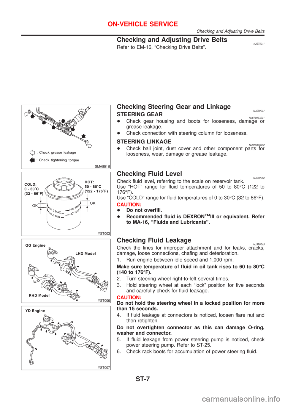
Checking Steering Gear and LinkageNJST0037STEERING GEARNJST0037S01+Check gear housing and boots for looseness, damage or
grease leakage.
+Check connection with steering column for looseness.
STEERING LINKAGENJST0037S02+Check ball joint, dust cover and other component parts for
looseness, wear, damage or grease leakage.
YST003
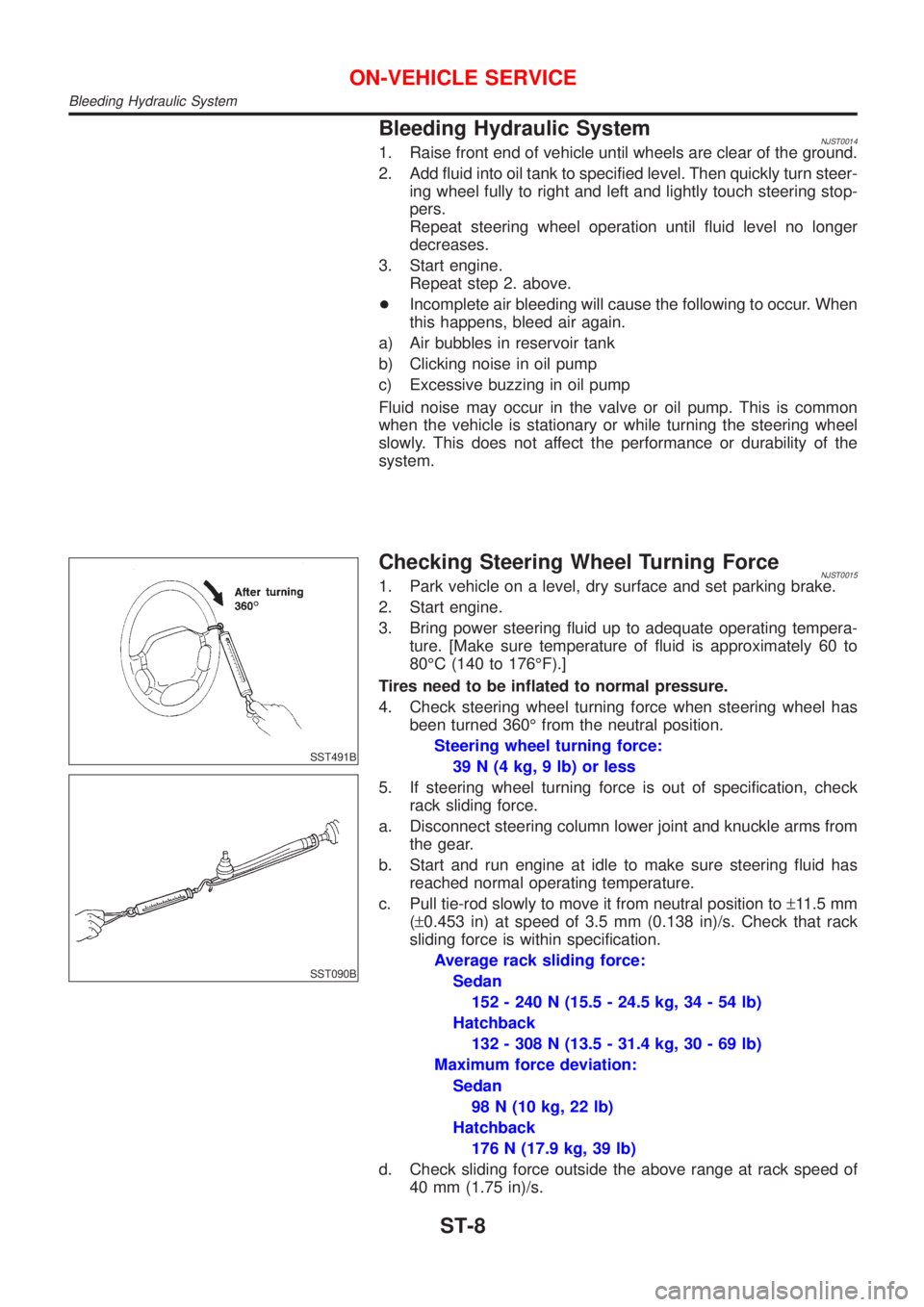
Checking Fluid LevelNJST0012Check fluid level, referring to the scale on reservoir tank.
Use ªHOTº range for fluid temperatures of 50 to 80ÉC (122 to
176ÉF).
Use ªCOLDº range for fluid temperatures of 0 to 30ÉC (32 to 86ÉF).
CAUTION:
+Do not overfill.
+Recommended fluid is DEXRON
TMIII or equivalent. Refer
to MA-16, ªFluids and Lubricantsº.
YST006
YST007
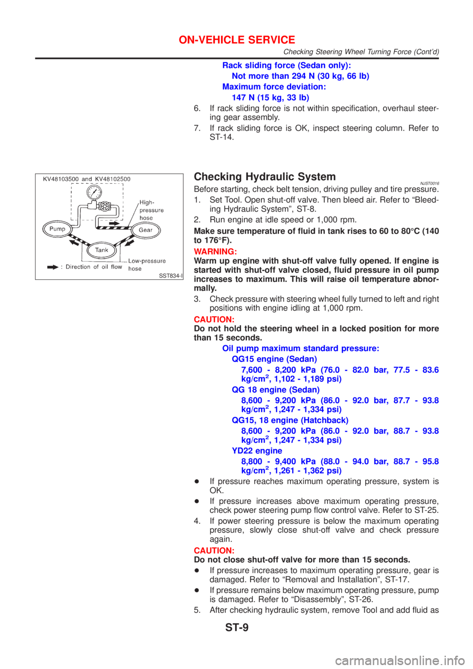
Checking Fluid LeakageNJST0013Check the lines for improper attachment and for leaks, cracks,
damage, loose connections, chafing and deterioration.
1. Run engine between idle speed and 1,000 rpm.
Make sure temperature of fluid in oil tank rises to 60 to 80ÉC
(140 to 176ÉF).
2. Turn steering wheel right-to-left several times.
3. Hold steering wheel at each ªlockº position for five seconds
and carefully check for fluid leakage.
CAUTION:
Do not hold the steering wheel in a locked position for more
than 15 seconds.
4. If fluid leakage at connectors is noticed, loosen flare nut and
then retighten.
Do not overtighten connector as this can damage O-ring,
washer and connector.
5. If fluid leakage from power steering pump is noticed, check
power steering pump. Refer to ST-25.
6. Check rack boots for accumulation of power steering fluid.
ON-VEHICLE SERVICE
Checking and Adjusting Drive Belts
ST-7
Page 2844 of 2898
Bleeding Hydraulic SystemNJST00141. Raise front end of vehicle until wheels are clear of the ground.
2. Add fluid into oil tank to specified level. Then quickly turn steer-
ing wheel fully to right and left and lightly touch steering stop-
pers.
Repeat steering wheel operation until fluid level no longer
decreases.
3. Start engine.
Repeat step 2. above.
+Incomplete air bleeding will cause the following to occur. When
this happens, bleed air again.
a) Air bubbles in reservoir tank
b) Clicking noise in oil pump
c) Excessive buzzing in oil pump
Fluid noise may occur in the valve or oil pump. This is common
when the vehicle is stationary or while turning the steering wheel
slowly. This does not affect the performance or durability of the
system.
SST491B
SST090B
Checking Steering Wheel Turning ForceNJST00151. Park vehicle on a level, dry surface and set parking brake.
2. Start engine.
3. Bring power steering fluid up to adequate operating tempera-
ture. [Make sure temperature of fluid is approximately 60 to
80ÉC (140 to 176ÉF).]
Tires need to be inflated to normal pressure.
4. Check steering wheel turning force when steering wheel has
been turned 360É from the neutral position.
Steering wheel turning force:
39 N (4 kg, 9 lb) or less
5. If steering wheel turning force is out of specification, check
rack sliding force.
a. Disconnect steering column lower joint and knuckle arms from
the gear.
b. Start and run engine at idle to make sure steering fluid has
reached normal operating temperature.
c. Pull tie-rod slowly to move it from neutral position to±11.5 mm
(±0.453 in) at speed of 3.5 mm (0.138 in)/s. Check that rack
sliding force is within specification.
Average rack sliding force:
Sedan
152 - 240 N (15.5 - 24.5 kg, 34 - 54 lb)
Hatchback
132 - 308 N (13.5 - 31.4 kg, 30 - 69 lb)
Maximum force deviation:
Sedan
98 N (10 kg, 22 lb)
Hatchback
176 N (17.9 kg, 39 lb)
d. Check sliding force outside the above range at rack speed of
40 mm (1.75 in)/s.
ON-VEHICLE SERVICE
Bleeding Hydraulic System
ST-8
Page 2845 of 2898
Rack sliding force (Sedan only):
Not more than 294 N (30 kg, 66 lb)
Maximum force deviation:
147 N (15 kg, 33 lb)
6. If rack sliding force is not within specification, overhaul steer-
ing gear assembly.
7. If rack sliding force is OK, inspect steering column. Refer to
ST-14.
SST834-I
Checking Hydraulic SystemNJST0016Before starting, check belt tension, driving pulley and tire pressure.
1. Set Tool. Open shut-off valve. Then bleed air. Refer to ªBleed-
ing Hydraulic Systemº, ST-8.
2. Run engine at idle speed or 1,000 rpm.
Make sure temperature of fluid in tank rises to 60 to 80ÉC (140
to 176ÉF).
WARNING:
Warm up engine with shut-off valve fully opened. If engine is
started with shut-off valve closed, fluid pressure in oil pump
increases to maximum. This will raise oil temperature abnor-
mally.
3. Check pressure with steering wheel fully turned to left and right
positions with engine idling at 1,000 rpm.
CAUTION:
Do not hold the steering wheel in a locked position for more
than 15 seconds.
Oil pump maximum standard pressure:
QG15 engine (Sedan)
7,600 - 8,200 kPa (76.0 - 82.0 bar, 77.5 - 83.6
kg/cm
2, 1,102 - 1,189 psi)
QG 18 engine (Sedan)
8,600 - 9,200 kPa (86.0 - 92.0 bar, 87.7 - 93.8
kg/cm
2, 1,247 - 1,334 psi)
QG15, 18 engine (Hatchback)
8,600 - 9,200 kPa (86.0 - 92.0 bar, 88.7 - 93.8
kg/cm
2, 1,247 - 1,334 psi)
YD22 engine
8,800 - 9,400 kPa (88.0 - 94.0 bar, 88.7 - 95.8
kg/cm
2, 1,261 - 1,362 psi)
+If pressure reaches maximum operating pressure, system is
OK.
+If pressure increases above maximum operating pressure,
check power steering pump flow control valve. Refer to ST-25.
4. If power steering pressure is below the maximum operating
pressure, slowly close shut-off valve and check pressure
again.
CAUTION:
Do not close shut-off valve for more than 15 seconds.
+If pressure increases to maximum operating pressure, gear is
damaged. Refer to ªRemoval and Installationº, ST-17.
+If pressure remains below maximum operating pressure, pump
is damaged. Refer to ªDisassemblyº, ST-26.
5. After checking hydraulic system, remove Tool and add fluid as
ON-VEHICLE SERVICE
Checking Steering Wheel Turning Force (Cont'd)
ST-9
Page 2860 of 2898
SST713C
10. Prevent adjusting screw from turning, and tighten lock nut to
specified torque.
SST090B
11. Check rack sliding force on vehicle as follows:
a. Install steering gear onto vehicle, but do not connect tie-rod to
knuckle arm.
b. Connect all piping and fill with steering fluid.
c. Start engine and bleed air completely.
d. Disconnect steering column lower joint from the gear.
e. Keep engine at idle and make sure steering fluid has reached
normal operating temperature.
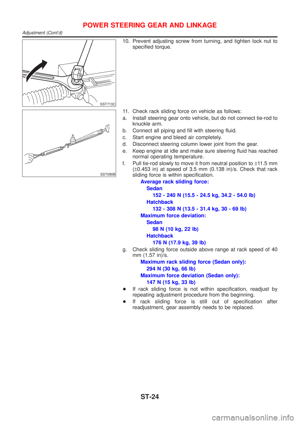
f. Pull tie-rod slowly to move it from neutral position to±11.5 mm
(±0.453 in) at speed of 3.5 mm (0.138 in)/s. Check that rack
sliding force is within specification.
Average rack sliding force:
Sedan
152 - 240 N (15.5 - 24.5 kg, 34.2 - 54.0 lb)
Hatchback
132 - 308 N (13.5 - 31.4 kg, 30 - 69 lb)
Maximum force deviation:
Sedan
98 N (10 kg, 22 lb)
Hatchback
176 N (17.9 kg, 39 lb)
g. Check sliding force outside above range at rack speed of 40
mm (1.57 in)/s.
Maximum rack sliding force (Sedan only):
294 N (30 kg, 66 lb)
Maximum force deviation (Sedan only):
147 N (15 kg, 33 lb)
+If rack sliding force is not within specification, readjust by
repeating adjustment procedure from the beginning.
+If rack sliding force is still out of specification after
readjustment, gear assembly needs to be replaced.
POWER STEERING GEAR AND LINKAGE
Adjustment (Cont'd)
ST-24