2001 NISSAN ALMERA engine
[x] Cancel search: enginePage 2703 of 2898
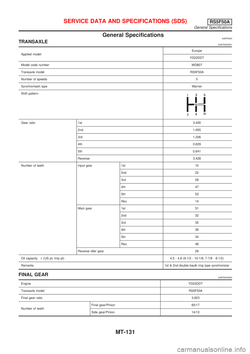
General SpecificationsNJMT0024TRANSAXLENJMT0024S01
Applied modelEurope
YD22DDT
Model code numberWD807
Transaxle modelRS5F50A
Number of speeds5
Synchromesh typeWarner
Shift pattern
Gear ratio 1st3.400
2nd1.955
3rd1.206
4th0.829
5th0.641
Reverse3.428
Number of teeth Input gear 1st 15
2nd 22
3rd 29
4th 47
5th 53
Rev. 14
Main gear 1st 51
2nd 32
3rd 35
4th 39
5th 34
Rev. 48
Reverse idler gear 29
Oil capacity!(US pt, Imp pt)4.5 - 4.8 (9-1/2 - 10-1/8, 7-7/8 - 8-1/2)
Remarks1st & 2nd double baulk ring type synchronizer
FINAL GEARNJMT0024S02
EngineYD22DDT
Transaxle modelRS5F50A
Final gear ratio3.823
Number of teethFinal gear/Pinion 65/17
Side gear/Pinion 14/10
SERVICE DATA AND SPECIFICATIONS (SDS)RS5F50A
General Specifications
MT-131
Page 2797 of 2898
STARTING & CHARGING SYSTEMS
SECTION
SC
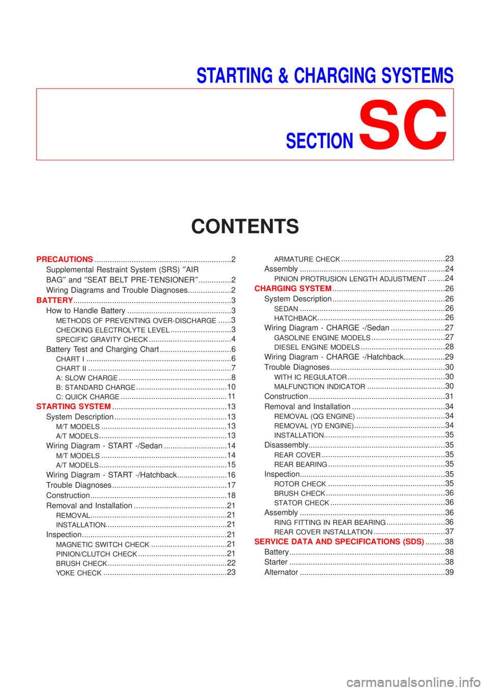
CONTENTS
PRECAUTIONS...............................................................2
Supplemental Restraint System (SRS)²AIR
BAG²and²SEAT BELT PRE-TENSIONER²...............2
Wiring Diagrams and Trouble Diagnoses....................2
BATTERY.........................................................................3
How to Handle Battery ................................................3
METHODS OF PREVENTING OVER-DISCHARGE......3
CHECKING ELECTROLYTE LEVEL............................3
SPECIFIC GRAVITY CHECK......................................4
Battery Test and Charging Chart .................................6
CHART I...................................................................6
CHART II..................................................................7
A: SLOW CHARGE....................................................8
B: STANDARD CHARGE..........................................10
C: QUICK CHARGE................................................. 11
STARTING SYSTEM.....................................................13
System Description ....................................................13
M/T MODELS..........................................................13
A/T MODELS...........................................................13
Wiring Diagram - START -/Sedan .............................14
M/T MODELS..........................................................14
A/T MODELS...........................................................15
Wiring Diagram - START -/Hatchback.......................16
Trouble Diagnoses.....................................................17
Construction ...............................................................18
Removal and Installation ...........................................21
REMOVAL...............................................................21
INSTALLATION........................................................21
Inspection...................................................................21
MAGNETIC SWITCH CHECK...................................21
PINION/CLUTCH CHECK.........................................21
BRUSH CHECK.......................................................22
YOKE CHECK.........................................................23
ARMATURE CHECK................................................23
Assembly ...................................................................24
PINION PROTRUSION LENGTH ADJUSTMENT........24
CHARGING SYSTEM....................................................26
System Description ....................................................26
SEDAN...................................................................26
HATCHBACK...........................................................26
Wiring Diagram - CHARGE -/Sedan .........................27
GASOLINE ENGINE MODELS..................................27
DIESEL ENGINE MODELS.......................................28
Wiring Diagram - CHARGE -/Hatchback...................29
Trouble Diagnoses.....................................................30
WITH IC REGULATOR.............................................30
MALFUNCTION INDICATOR....................................30
Construction ...............................................................31
Removal and Installation ...........................................34
REMOVAL (QG ENGINE).........................................34
REMOVAL (YD ENGINE)..........................................34
INSTALLATION........................................................35
Disassembly...............................................................35
REAR COVER.........................................................35
REAR BEARING......................................................35
Inspection...................................................................35
ROTOR CHECK......................................................35
BRUSH CHECK.......................................................36
STATOR CHECK.....................................................36
Assembly ...................................................................36
RING FITTING IN REAR BEARING...........................36
REAR COVER INSTALLATION.................................37
SERVICE DATA AND SPECIFICATIONS (SDS).........38
Battery........................................................................38
Starter ........................................................................38
Alternator ...................................................................39
Page 2799 of 2898
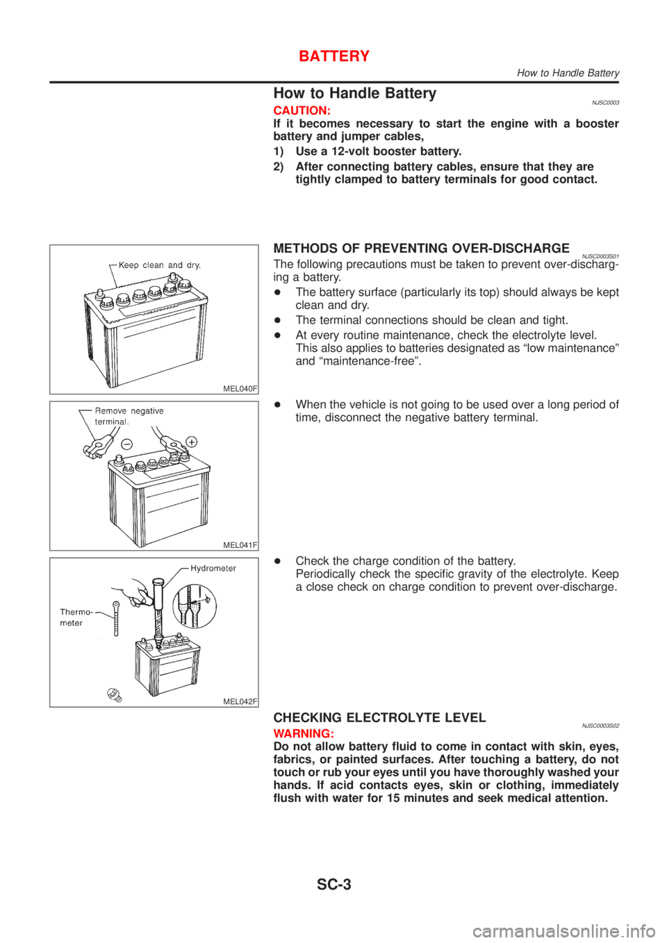
How to Handle BatteryNJSC0003CAUTION:
If it becomes necessary to start the engine with a booster
battery and jumper cables,
1) Use a 12-volt booster battery.
2) After connecting battery cables, ensure that they are
tightly clamped to battery terminals for good contact.
MEL040F
METHODS OF PREVENTING OVER-DISCHARGENJSC0003S01The following precautions must be taken to prevent over-discharg-
ing a battery.
+The battery surface (particularly its top) should always be kept
clean and dry.
+The terminal connections should be clean and tight.
+At every routine maintenance, check the electrolyte level.
This also applies to batteries designated as ªlow maintenanceº
and ªmaintenance-freeº.
MEL041F
+When the vehicle is not going to be used over a long period of
time, disconnect the negative battery terminal.
MEL042F
+Check the charge condition of the battery.
Periodically check the specific gravity of the electrolyte. Keep
a close check on charge condition to prevent over-discharge.
CHECKING ELECTROLYTE LEVELNJSC0003S02WARNING:
Do not allow battery fluid to come in contact with skin, eyes,
fabrics, or painted surfaces. After touching a battery, do not
touch or rub your eyes until you have thoroughly washed your
hands. If acid contacts eyes, skin or clothing, immediately
flush with water for 15 minutes and seek medical attention.
BATTERY
How to Handle Battery
SC-3
Page 2809 of 2898
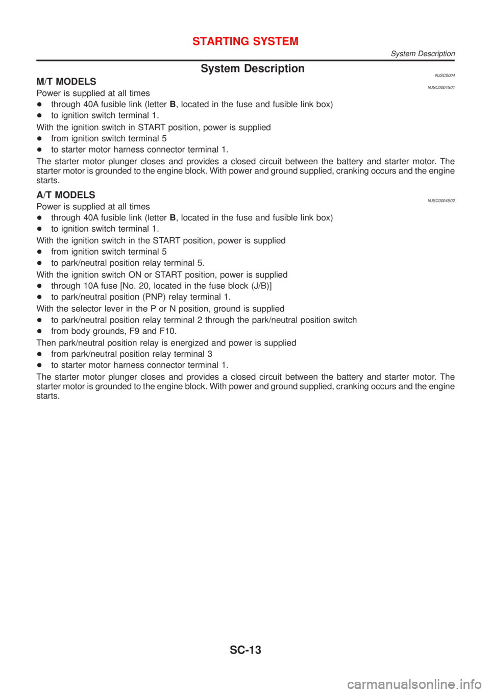
System DescriptionNJSC0004M/T MODELSNJSC0004S01Power is supplied at all times
+through 40A fusible link (letterB, located in the fuse and fusible link box)
+to ignition switch terminal 1.
With the ignition switch in START position, power is supplied
+from ignition switch terminal 5
+to starter motor harness connector terminal 1.
The starter motor plunger closes and provides a closed circuit between the battery and starter motor. The
starter motor is grounded to the engine block. With power and ground supplied, cranking occurs and the engine
starts.
A/T MODELSNJSC0004S02Power is supplied at all times
+through 40A fusible link (letterB, located in the fuse and fusible link box)
+to ignition switch terminal 1.
With the ignition switch in the START position, power is supplied
+from ignition switch terminal 5
+to park/neutral position relay terminal 5.
With the ignition switch ON or START position, power is supplied
+through 10A fuse [No. 20, located in the fuse block (J/B)]
+to park/neutral position (PNP) relay terminal 1.
With the selector lever in the P or N position, ground is supplied
+to park/neutral position relay terminal 2 through the park/neutral position switch
+from body grounds, F9 and F10.
Then park/neutral position relay is energized and power is supplied
+from park/neutral position relay terminal 3
+to starter motor harness connector terminal 1.
The starter motor plunger closes and provides a closed circuit between the battery and starter motor. The
starter motor is grounded to the engine block. With power and ground supplied, cranking occurs and the engine
starts.
STARTING SYSTEM
System Description
SC-13
Page 2820 of 2898
SEL022Z
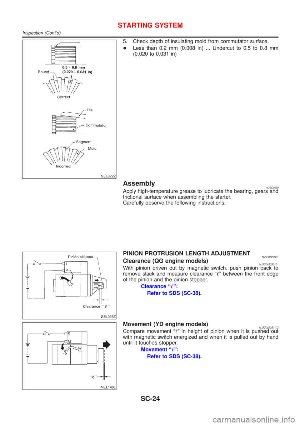
5. Check depth of insulating mold from commutator surface.
+Less than 0.2 mm (0.008 in) ... Undercut to 0.5 to 0.8 mm
(0.020 to 0.031 in)
AssemblyNJSC0020Apply high-temperature grease to lubricate the bearing, gears and
frictional surface when assembling the starter.
Carefully observe the following instructions.
SEL026Z
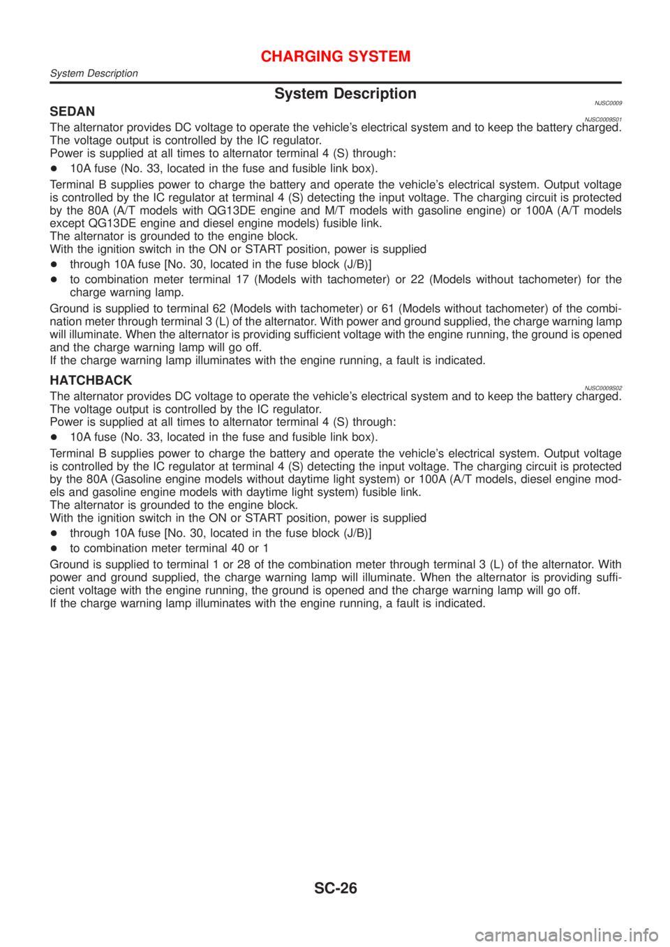
PINION PROTRUSION LENGTH ADJUSTMENTNJSC0020S01Clearance (QG engine models)NJSC0020S0101With pinion driven out by magnetic switch, push pinion back to
remove slack and measure clearance ª!º between the front edge
of the pinion and the pinion stopper.
Clearance ª!º:
Refer to SDS (SC-38).
MEL140L
Movement (YD engine models)NJSC0020S0102Compare movement ª!º in height of pinion when it is pushed out
with magnetic switch energized and when it is pulled out by hand
until it touches stopper.
Movement ª!º:
Refer to SDS (SC-38).
STARTING SYSTEM
Inspection (Cont'd)
SC-24
Page 2822 of 2898
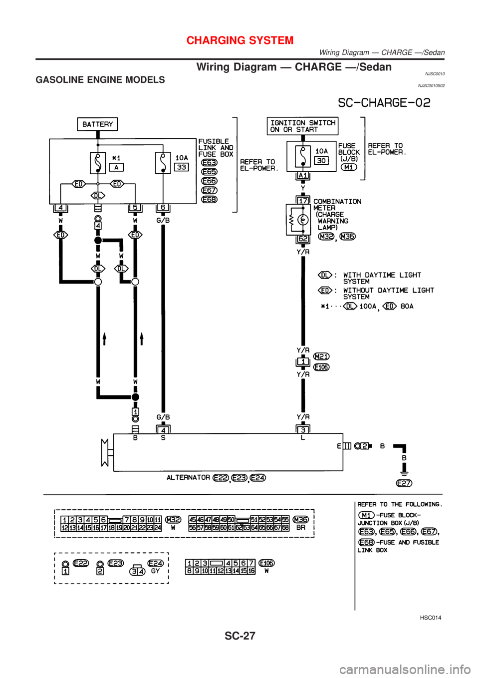
System DescriptionNJSC0009SEDANNJSC0009S01The alternator provides DC voltage to operate the vehicle's electrical system and to keep the battery charged.
The voltage output is controlled by the IC regulator.
Power is supplied at all times to alternator terminal 4 (S) through:
+10A fuse (No. 33, located in the fuse and fusible link box).
Terminal B supplies power to charge the battery and operate the vehicle's electrical system. Output voltage
is controlled by the IC regulator at terminal 4 (S) detecting the input voltage. The charging circuit is protected
by the 80A (A/T models with QG13DE engine and M/T models with gasoline engine) or 100A (A/T models
except QG13DE engine and diesel engine models) fusible link.
The alternator is grounded to the engine block.
With the ignition switch in the ON or START position, power is supplied
+through 10A fuse [No. 30, located in the fuse block (J/B)]
+to combination meter terminal 17 (Models with tachometer) or 22 (Models without tachometer) for the
charge warning lamp.
Ground is supplied to terminal 62 (Models with tachometer) or 61 (Models without tachometer) of the combi-
nation meter through terminal 3 (L) of the alternator. With power and ground supplied, the charge warning lamp
will illuminate. When the alternator is providing sufficient voltage with the engine running, the ground is opened
and the charge warning lamp will go off.
If the charge warning lamp illuminates with the engine running, a fault is indicated.
HATCHBACKNJSC0009S02The alternator provides DC voltage to operate the vehicle's electrical system and to keep the battery charged.
The voltage output is controlled by the IC regulator.
Power is supplied at all times to alternator terminal 4 (S) through:
+10A fuse (No. 33, located in the fuse and fusible link box).
Terminal B supplies power to charge the battery and operate the vehicle's electrical system. Output voltage
is controlled by the IC regulator at terminal 4 (S) detecting the input voltage. The charging circuit is protected
by the 80A (Gasoline engine models without daytime light system) or 100A (A/T models, diesel engine mod-
els and gasoline engine models with daytime light system) fusible link.
The alternator is grounded to the engine block.
With the ignition switch in the ON or START position, power is supplied
+through 10A fuse [No. 30, located in the fuse block (J/B)]
+to combination meter terminal 40 or 1
Ground is supplied to terminal 1 or 28 of the combination meter through terminal 3 (L) of the alternator. With
power and ground supplied, the charge warning lamp will illuminate. When the alternator is providing suffi-
cient voltage with the engine running, the ground is opened and the charge warning lamp will go off.
If the charge warning lamp illuminates with the engine running, a fault is indicated.
CHARGING SYSTEM
System Description
SC-26
Page 2823 of 2898
Wiring Diagram Ð CHARGE Ð/SedanNJSC0010GASOLINE ENGINE MODELSNJSC0010S02
HSC014
CHARGING SYSTEM
Wiring Diagram Ð CHARGE Ð/Sedan
SC-27
Page 2824 of 2898
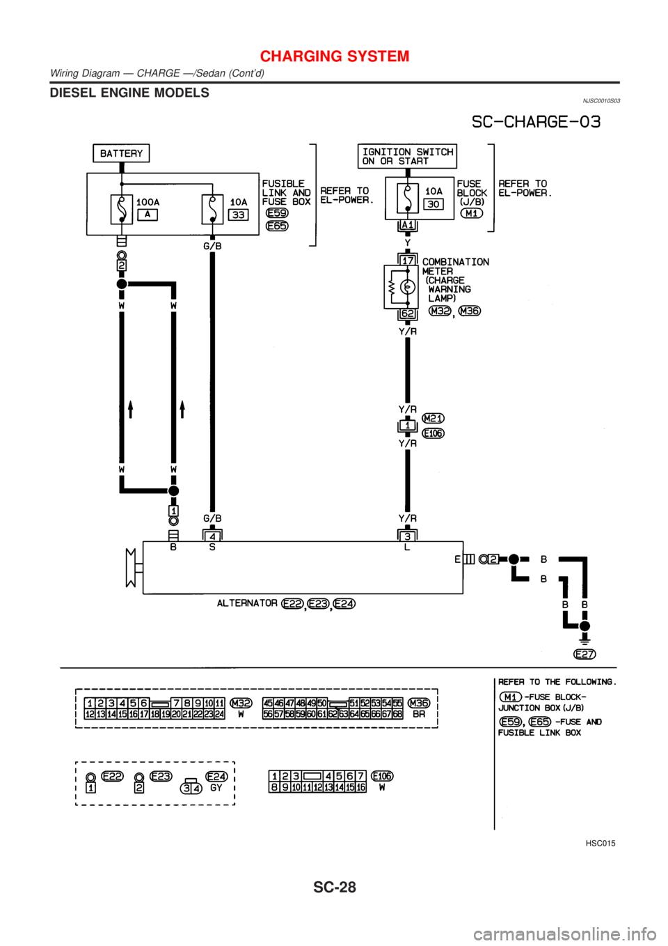
DIESEL ENGINE MODELSNJSC0010S03
HSC015
CHARGING SYSTEM
Wiring Diagram Ð CHARGE Ð/Sedan (Cont'd)
SC-28