Page 2534 of 2898

SLC283B
JLC284B
SLC926-A
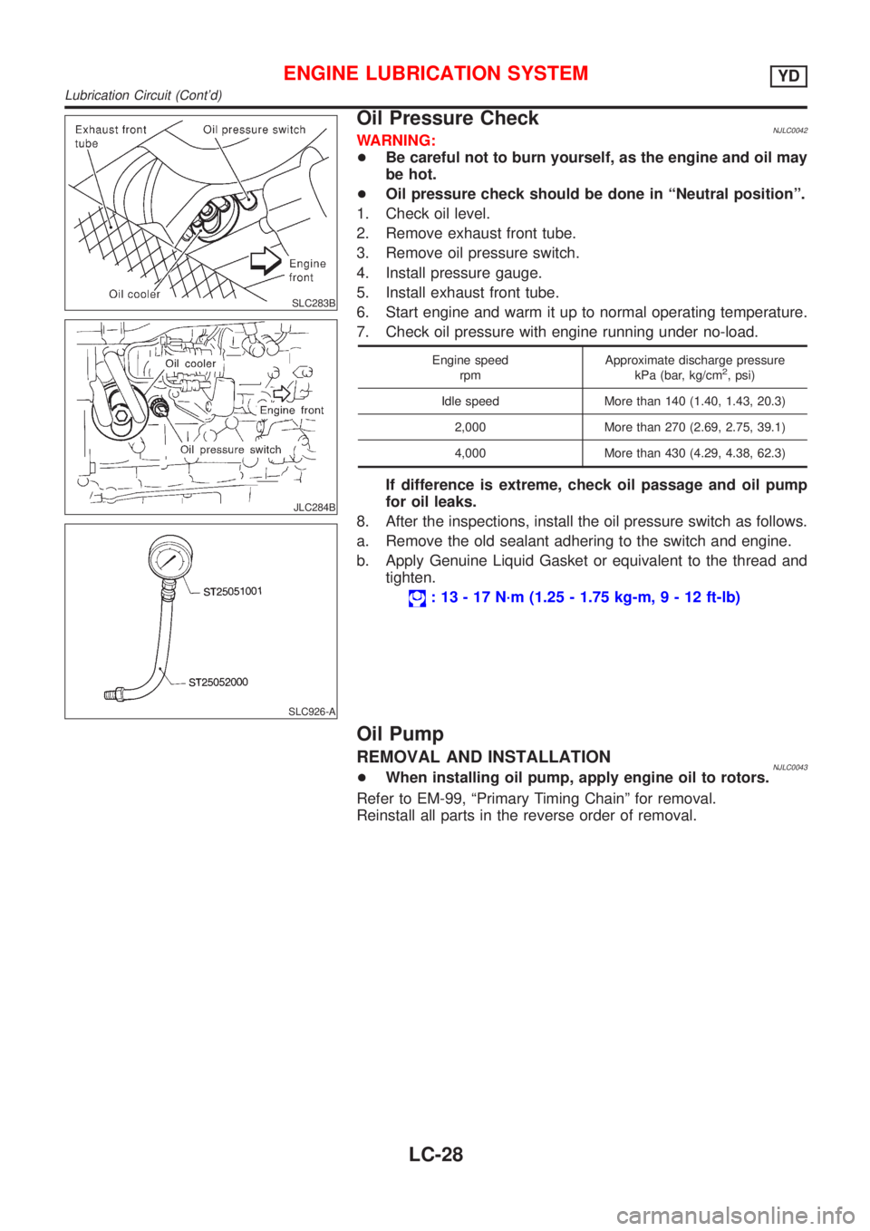
Oil Pressure CheckNJLC0042WARNING:
+Be careful not to burn yourself, as the engine and oil may
be hot.
+Oil pressure check should be done in ªNeutral positionº.
1. Check oil level.
2. Remove exhaust front tube.
3. Remove oil pressure switch.
4. Install pressure gauge.
5. Install exhaust front tube.
6. Start engine and warm it up to normal operating temperature.
7. Check oil pressure with engine running under no-load.
Engine speed
rpmApproximate discharge pressure
kPa (bar, kg/cm2, psi)
Idle speed More than 140 (1.40, 1.43, 20.3)
2,000 More than 270 (2.69, 2.75, 39.1)
4,000 More than 430 (4.29, 4.38, 62.3)
If difference is extreme, check oil passage and oil pump
for oil leaks.
8. After the inspections, install the oil pressure switch as follows.
a. Remove the old sealant adhering to the switch and engine.
b. Apply Genuine Liquid Gasket or equivalent to the thread and
tighten.
: 13 - 17 N´m (1.25 - 1.75 kg-m,9-12ft-lb)
Oil Pump
REMOVAL AND INSTALLATIONNJLC0043+When installing oil pump, apply engine oil to rotors.
Refer to EM-99, ªPrimary Timing Chainº for removal.
Reinstall all parts in the reverse order of removal.
ENGINE LUBRICATION SYSTEMYD
Lubrication Circuit (Cont'd)
LC-28
Page 2535 of 2898
DISASSEMBLY AND ASSEMBLYNJLC0044
JLC285B
JLC286B
JLC355B
OIL PUMP INSPECTIONNJLC0045+Install the inner rotor and outer rotor with the punched
marks on the pump cover side.
Using a feeler gauge, straightedge and micrometers, check the
following clearances:
Unit: mm (in)
Body to outer rotor radial clearance10.114 - 0.260 (0.0045 - 0.0102)
Inner rotor to outer rotor tip clearance
2Below 0.18 (0.0071)
Body to inner rotor axial clearance30.050 - 0.090 (0.0020 - 0.0035)
Body to outer rotor axial clearance40.030 - 0.190 (0.0012 - 0.0075)
Inner rotor to brazed portion of hous-
ing clearance50.045 - 0.091 (0.0018 - 0.0036)
+If the tip clearance (2) exceeds the limit, replace rotor set.
+If body to rotor clearances (1, 3, 4, 5) exceed the limit,
replace oil pump body assembly.
ENGINE LUBRICATION SYSTEMYD
Oil Pump (Cont'd)
LC-29
Page 2536 of 2898
JLC356B
JLC338B
REGULATOR VALVE INSPECTIONNJLC00461. Visually inspect components for wear and damage.
2. Check oil pressure regulator valve sliding surface and valve
spring.
3. Coat regulator valve with engine oil. Check that it falls
smoothly into the valve hole by its own weight.
If damaged, replace regulator valve set or oil pump body.
JLC358B
4. Check regulator valve to oil pump body clearance.
Clearance 6:
6 : 0.040 - 0.097 mm (0.0016 - 0.0038 in)
If it exceeds the limit, replace oil pump body.
ENGINE LUBRICATION SYSTEMYD
Oil Pump (Cont'd)
LC-30
Page 2537 of 2898

SLC287B
JLC288B
Changing Engine OilNJLC0074WARNING:
+Be careful not to burn yourself, as the engine oil is hot.
+Prolonged and repeated contact with used engine oil may
cause skin cancer; try to avoid direct skin contact with
used oil. If skin contact is made, wash thoroughly with
soap or hand cleaner as soon as possible.
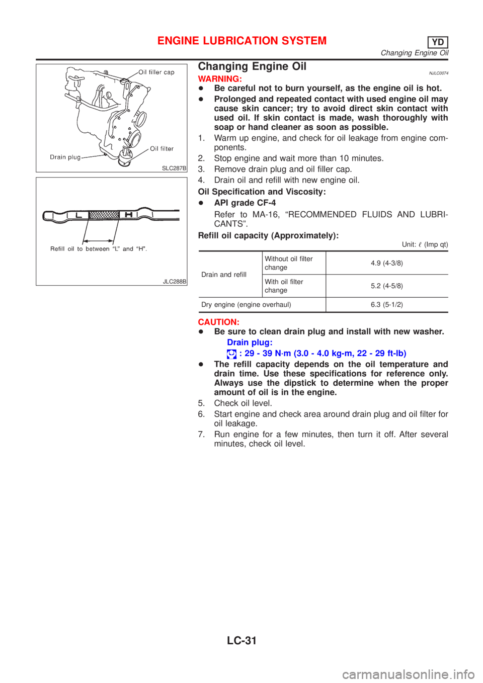
1. Warm up engine, and check for oil leakage from engine com-
ponents.
2. Stop engine and wait more than 10 minutes.
3. Remove drain plug and oil filler cap.
4. Drain oil and refill with new engine oil.
Oil Specification and Viscosity:
+API grade CF-4
Refer to MA-16, ªRECOMMENDED FLUIDS AND LUBRI-
CANTSº.
Refill oil capacity (Approximately):
Unit:!(Imp qt)
Drain and refillWithout oil filter
change4.9 (4-3/8)
With oil filter
change5.2 (4-5/8)
Dry engine (engine overhaul) 6.3 (5-1/2)
CAUTION:
+Be sure to clean drain plug and install with new washer.
Drain plug:
: 29 - 39 N´m (3.0 - 4.0 kg-m, 22 - 29 ft-lb)
+The refill capacity depends on the oil temperature and
drain time. Use these specifications for reference only.
Always use the dipstick to determine when the proper
amount of oil is in the engine.
5. Check oil level.
6. Start engine and check area around drain plug and oil filter for
oil leakage.
7. Run engine for a few minutes, then turn it off. After several
minutes, check oil level.
ENGINE LUBRICATION SYSTEMYD
Changing Engine Oil
LC-31
Page 2538 of 2898
Oil Filter BracketNJLC0075
JLC301B
REMOVAL AND INSTALLATIONNJLC0075S011. Remove the undercover.
2. Steer the front wheel to the right.
3. Remove the right splash cover.
4. Remove the oil filter bracket bolt.
5. Reinstall all removed parts in the reverse order of removal.
+Insert the top mounting bolt to the oil filter bracket beforehand,
and set the oil filter bracket to the installation location.
JLC289B
Changing Oil FilterNJLC0076
ENGINE LUBRICATION SYSTEMYD
Oil Filter Bracket
LC-32
Page 2539 of 2898
![NISSAN ALMERA 2001 Service Manual SLC428B
REMOVALNJLC0076S011. Using a socket wrench [plane-to-plane width: 17 mm (0.67 in)],
loosen the filter body approximately four turns.
JLC291B
2. Drain the oil after matching the ªDRAINº arrow NISSAN ALMERA 2001 Service Manual SLC428B
REMOVALNJLC0076S011. Using a socket wrench [plane-to-plane width: 17 mm (0.67 in)],
loosen the filter body approximately four turns.
JLC291B
2. Drain the oil after matching the ªDRAINº arrow](/manual-img/5/57348/w960_57348-2538.png)
SLC428B
REMOVALNJLC0076S011. Using a socket wrench [plane-to-plane width: 17 mm (0.67 in)],
loosen the filter body approximately four turns.
JLC291B
2. Drain the oil after matching the ªDRAINº arrow mark at the
bottom of the filter body to the protrusion on the oil filter
bracket.
+Catch the oil with a pan or cloth.
CAUTION:
+The drained oil flows over the right surface of the filter
body.
+Completely wipe clean any engine oil remaining on the
filter body or vehicle.
3. Remove the filter body, then remove the oil filter element.
JLC292B
4. Remove the O-ring from the filter body.
+Push the O-ring in one direction, lift the slack part using
fingers, and remove the O-ring from the filter body.
CAUTION:
Do not use wires or flat-bladed screwdrivers etc. as they may
cause damage to the filter body.
INSTALLATIONNJLC0076S021. Completely remove all foreign objects adhering to the inside of
the filter body or O-ring mounting area (body side and bracket
side).
2. Install the oil filter element and O-ring to the filter body.
+Push the oil filter element into the filter body completely.
3. Install the filter body to the oil filter bracket.
: 20 - 24 N´m (2.0 - 2.5 kg-m, 15 - 18 ft-lb)
4. After warming up the engine, check for engine oil leakage.
ENGINE LUBRICATION SYSTEMYD
Changing Oil Filter (Cont'd)
LC-33
Page 2540 of 2898
Oil CoolerNJLC0077
JLC312B
REMOVAL AND INSTALLATIONNJLC0077S011. Draining the coolant
Refer to LC-44, ªChanging Engine Coolantº.
2. Remove the exhaust front tube.
SLC359B
3. Reinstall all removed parts in the reverse order of removal.
+Confirm that no foreign objects are adhering to the installation
planes of the oil cooler or block.
+Tighten the connecting bolt after aligning the stopper on the
cylinder block side with protrusion of the oil cooler.
ENGINE LUBRICATION SYSTEMYD
Oil Cooler
LC-34
Page 2541 of 2898

Service Data and Specifications (SDS)
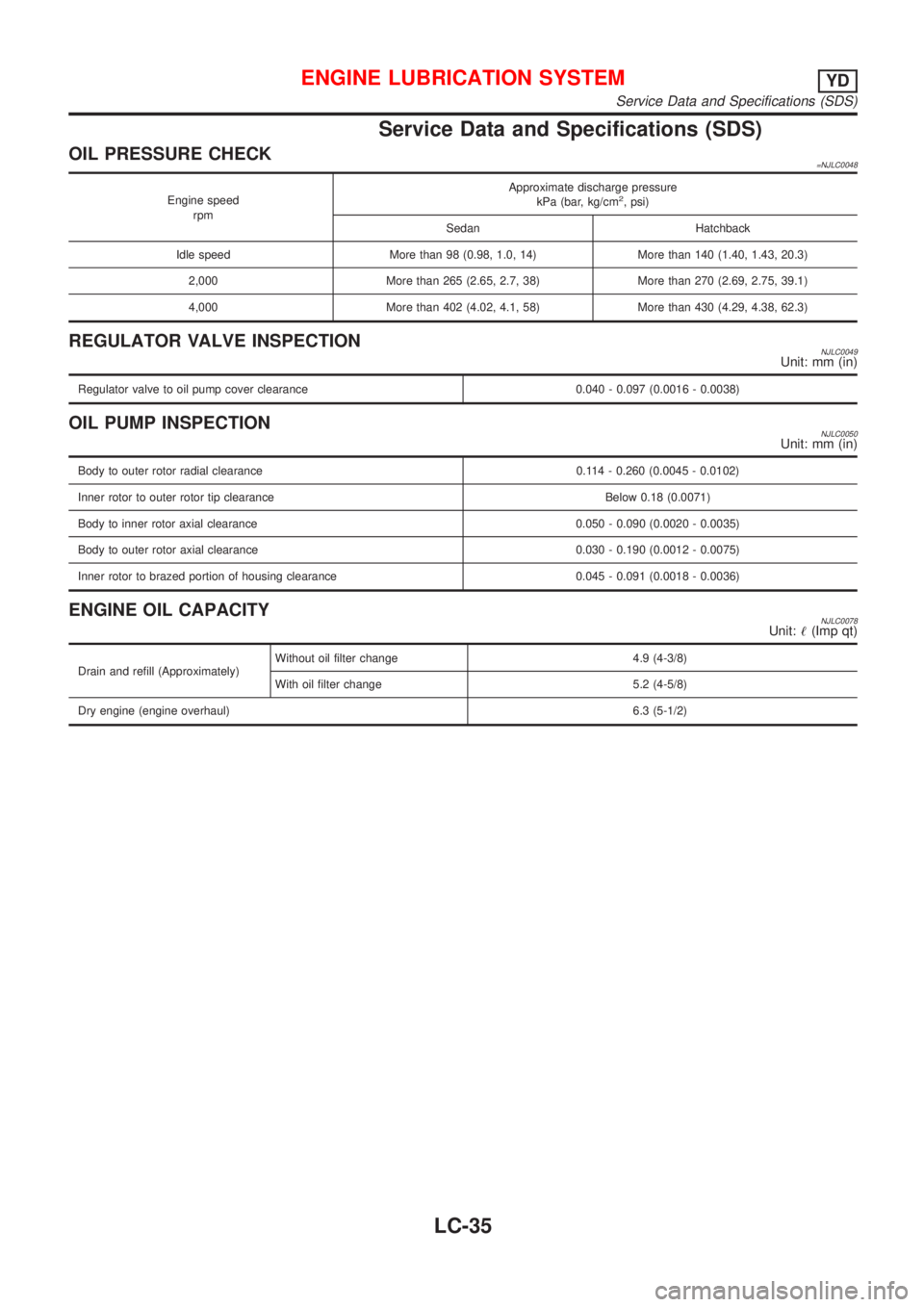
OIL PRESSURE CHECK=NJLC0048
Engine speed
rpmApproximate discharge pressure
kPa (bar, kg/cm2, psi)
Sedan Hatchback
Idle speed More than 98 (0.98, 1.0, 14) More than 140 (1.40, 1.43, 20.3)
2,000 More than 265 (2.65, 2.7, 38) More than 270 (2.69, 2.75, 39.1)
4,000 More than 402 (4.02, 4.1, 58) More than 430 (4.29, 4.38, 62.3)
REGULATOR VALVE INSPECTIONNJLC0049Unit: mm (in)
Regulator valve to oil pump cover clearance 0.040 - 0.097 (0.0016 - 0.0038)
OIL PUMP INSPECTIONNJLC0050Unit: mm (in)
Body to outer rotor radial clearance 0.114 - 0.260 (0.0045 - 0.0102)
Inner rotor to outer rotor tip clearance Below 0.18 (0.0071)
Body to inner rotor axial clearance 0.050 - 0.090 (0.0020 - 0.0035)
Body to outer rotor axial clearance 0.030 - 0.190 (0.0012 - 0.0075)
Inner rotor to brazed portion of housing clearance 0.045 - 0.091 (0.0018 - 0.0036)
ENGINE OIL CAPACITYNJLC0078Unit:!(Imp qt)
Drain and refill (Approximately)Without oil filter change 4.9 (4-3/8)
With oil filter change 5.2 (4-5/8)
Dry engine (engine overhaul)6.3 (5-1/2)
ENGINE LUBRICATION SYSTEMYD
Service Data and Specifications (SDS)
LC-35