Page 2526 of 2898

SMA182B
SMA412B
Refer to MA-16, ªRECOMMENDED FLUIDS AND LUBRI-
CANTSº.
Coolant capacity (With reservoir tank):
Unit:!(Imp qt)
M/T 6.7 (5-7/8)
A/TFor Sedan 6.6 (5-7/8)
For Hatchback 6.7 (5-7/8)
Reservoir tank capacity:
0.7!(5/8 Imp qt)
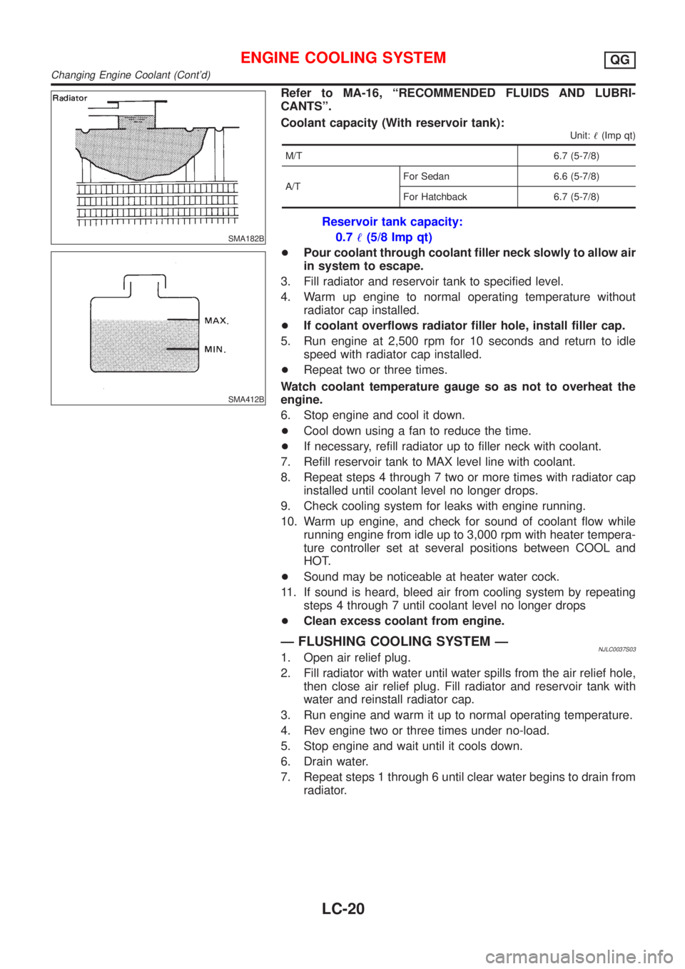
+Pour coolant through coolant filler neck slowly to allow air
in system to escape.
3. Fill radiator and reservoir tank to specified level.
4. Warm up engine to normal operating temperature without
radiator cap installed.
+If coolant overflows radiator filler hole, install filler cap.
5. Run engine at 2,500 rpm for 10 seconds and return to idle
speed with radiator cap installed.
+Repeat two or three times.
Watch coolant temperature gauge so as not to overheat the
engine.
6. Stop engine and cool it down.
+Cool down using a fan to reduce the time.
+If necessary, refill radiator up to filler neck with coolant.
7. Refill reservoir tank to MAX level line with coolant.
8. Repeat steps 4 through 7 two or more times with radiator cap
installed until coolant level no longer drops.
9. Check cooling system for leaks with engine running.
10. Warm up engine, and check for sound of coolant flow while
running engine from idle up to 3,000 rpm with heater tempera-
ture controller set at several positions between COOL and
HOT.
+Sound may be noticeable at heater water cock.
11. If sound is heard, bleed air from cooling system by repeating
steps 4 through 7 until coolant level no longer drops
+Clean excess coolant from engine.
Ð FLUSHING COOLING SYSTEM ÐNJLC0037S031. Open air relief plug.
2. Fill radiator with water until water spills from the air relief hole,
then close air relief plug. Fill radiator and reservoir tank with
water and reinstall radiator cap.
3. Run engine and warm it up to normal operating temperature.
4. Rev engine two or three times under no-load.
5. Stop engine and wait until it cools down.
6. Drain water.
7. Repeat steps 1 through 6 until clear water begins to drain from
radiator.
ENGINE COOLING SYSTEMQG
Changing Engine Coolant (Cont'd)
LC-20
Page 2527 of 2898
Radiator (Aluminum type)NJLC0081PREPARATIONNJLC0081S01
SLC882AB
SLC655C
1. Attach the spacer to the tip of the radiator plate pliers A.
Spacer specification: 1.5 mm (0.059 in) thick x 18 mm (0.71 in)
wide x 8.5 mm (0.335 in) long.
2. Make sure that when radiator plate pliers A are closed dimen-
sion H¢¢is approx. 7.6 mm (0.299 in).
3. Adjust dimension H¢¢with the spacer, if necessary.
SLC903
DISASSEMBLYNJLC0081S021. Remove tank with Tool.
SLC893
+Grip the crimped edge and bend it upwards so that Tool slips
off.
Do not bend excessively.
ENGINE COOLING SYSTEMQG
Radiator (Aluminum type)
LC-21
Page 2528 of 2898
SLC930
+In areas where Tool cannot be used, use a screwdriver to bend
the edge up.
Be careful not to damage tank.
SLC931
2. Make sure the edge stands straight up.
3. Remove oil cooler from tank. (A/T model only)
SLC894
ASSEMBLYNJLC0081S031. Install oil cooler. (A/T model only)
Pay attention to direction of conical washer.
SLC932
2. Clean contact portion of tank.
SLC917A
3. Install sealing rubber.
Push it in with fingers.
Be careful not to twist sealing rubber.
ENGINE COOLING SYSTEMQG
Radiator (Aluminum type) (Cont'd)
LC-22
Page 2529 of 2898
SLC904
4. Caulk tank in specified sequence with Tool.
SLC896
SLC897
+Use pliers in the locations where Tool cannot be used.
SLC554A
5. Make sure that the rim is completely crimped down.
Standard height ªHº:
8.0 - 8.4 mm (0.315 - 0.331 in)
6. Confirm that there is no leakage.
Refer to Inspection.
SLC933
INSPECTIONNJLC0081S041. Apply pressure with Tool.
Specified pressure value:
157 kPa (1.57 bar, 1.6 kg/cm
2, 23 psi)
WARNING:
To prevent the risk of the hose coming undone while under
pressure, securely fasten it down with a hose clamp.
Attach a hose to the oil cooler as well. (A/T model only)
ENGINE COOLING SYSTEMQG
Radiator (Aluminum type) (Cont'd)
LC-23
Page 2530 of 2898

SLC934
2. Check for leakage.
Overheating Cause AnalysisNJLC0028
Symptom Check items
Cooling sys-
tem parts
malfunctionPoor heat transferWater pump malfunction Worn or loose drive belt
Ð Thermostat stuck closed Ð
Damaged finsDust contamination or
paper clogging
Mechanical damage
Clogged radiator cooling
tubeExcess foreign material
(rust, dirt, sand, etc.)
Reduced air flowCooling fan does not oper-
ate
ÐÐ High resistance to fan rota-
tion
Damaged fan blades
Damaged radiator shroud Ð Ð Ð
Improper coolant mixture
ratioÐÐÐ
Poor coolant quality Ð Ð Ð
Insufficient coolantCoolant leaksCooling hoseLoose clamp
Cracked hose
Water pump Poor sealing
Radiator capLoose
Poor sealing
RadiatorO-ring for damage, deterio-
ration or improper fitting
Cracked radiator tank
Cracked radiator core
Reservoir tank Cracked reservoir tank
Overflowing reservoir tankExhaust gas leaks into
cooling systemCylinder head deterioration
Cylinder head gasket dete-
rioration
ENGINE COOLING SYSTEMQG
Radiator (Aluminum type) (Cont'd)
LC-24
Page 2531 of 2898

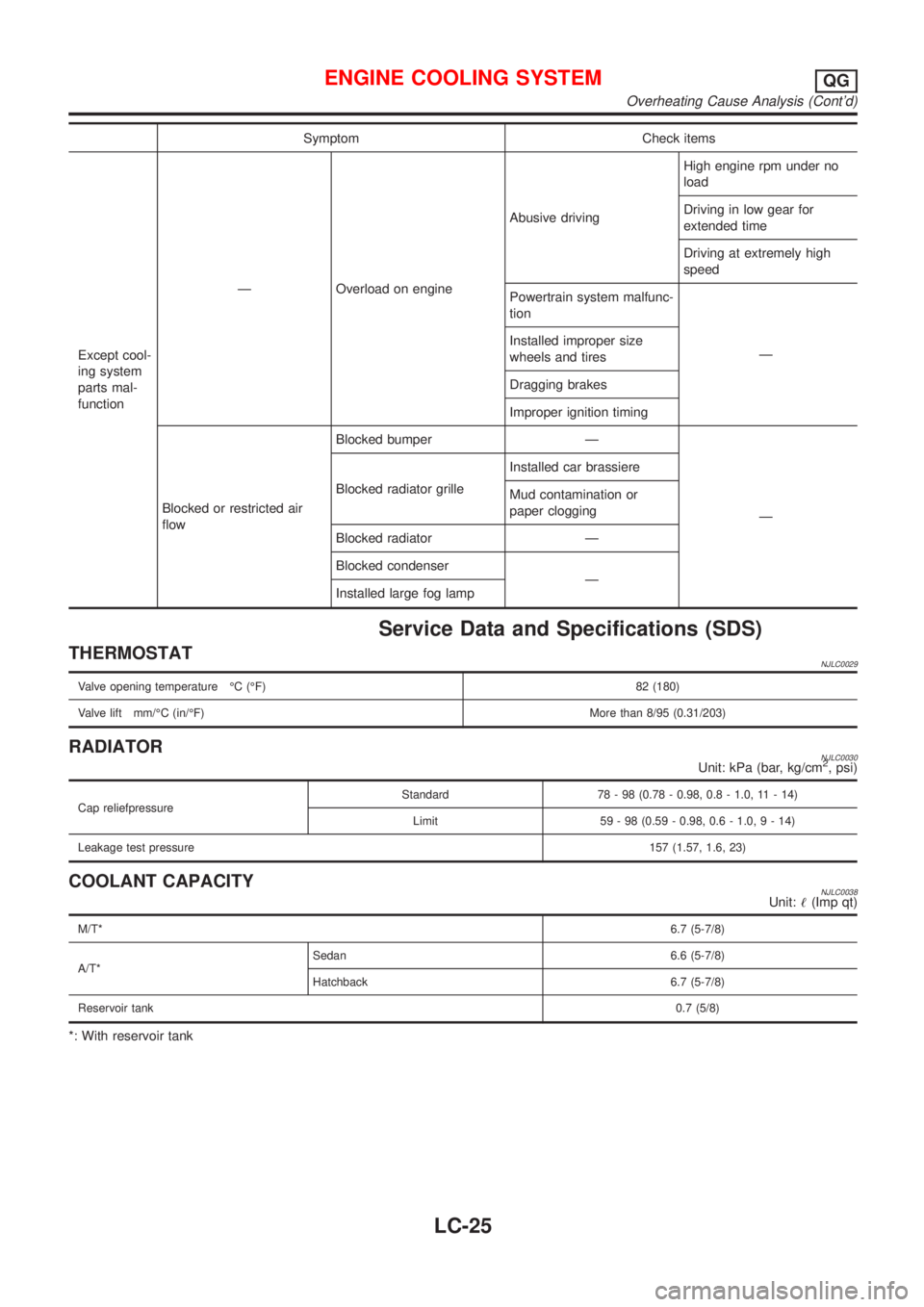
Symptom Check items
Except cool-
ing system
parts mal-
functionÐ Overload on engineAbusive drivingHigh engine rpm under no
load
Driving in low gear for
extended time
Driving at extremely high
speed
Powertrain system malfunc-
tion
Ð Installed improper size
wheels and tires
Dragging brakes
Improper ignition timing
Blocked or restricted air
flowBlocked bumper Ð
Ð Blocked radiator grilleInstalled car brassiere
Mud contamination or
paper clogging
Blocked radiator Ð
Blocked condenser
Ð
Installed large fog lamp
Service Data and Specifications (SDS)
THERMOSTATNJLC0029
Valve opening temperature ÉC (ÉF) 82 (180)
Valve lift mm/ÉC (in/ÉF)More than 8/95 (0.31/203)
RADIATORNJLC0030Unit: kPa (bar, kg/cm2, psi)
Cap reliefpressureStandard 78 - 98 (0.78 - 0.98, 0.8 - 1.0, 11 - 14)
Limit 59 - 98 (0.59 - 0.98, 0.6 - 1.0,9-14)
Leakage test pressure157 (1.57, 1.6, 23)
COOLANT CAPACITYNJLC0038Unit:!(Imp qt)
M/T*6.7 (5-7/8)
A/T*Sedan 6.6 (5-7/8)
Hatchback 6.7 (5-7/8)
Reservoir tank0.7 (5/8)
*: With reservoir tank
ENGINE COOLING SYSTEMQG
Overheating Cause Analysis (Cont'd)
LC-25
Page 2532 of 2898

SEM164F
AEM080
Precautions
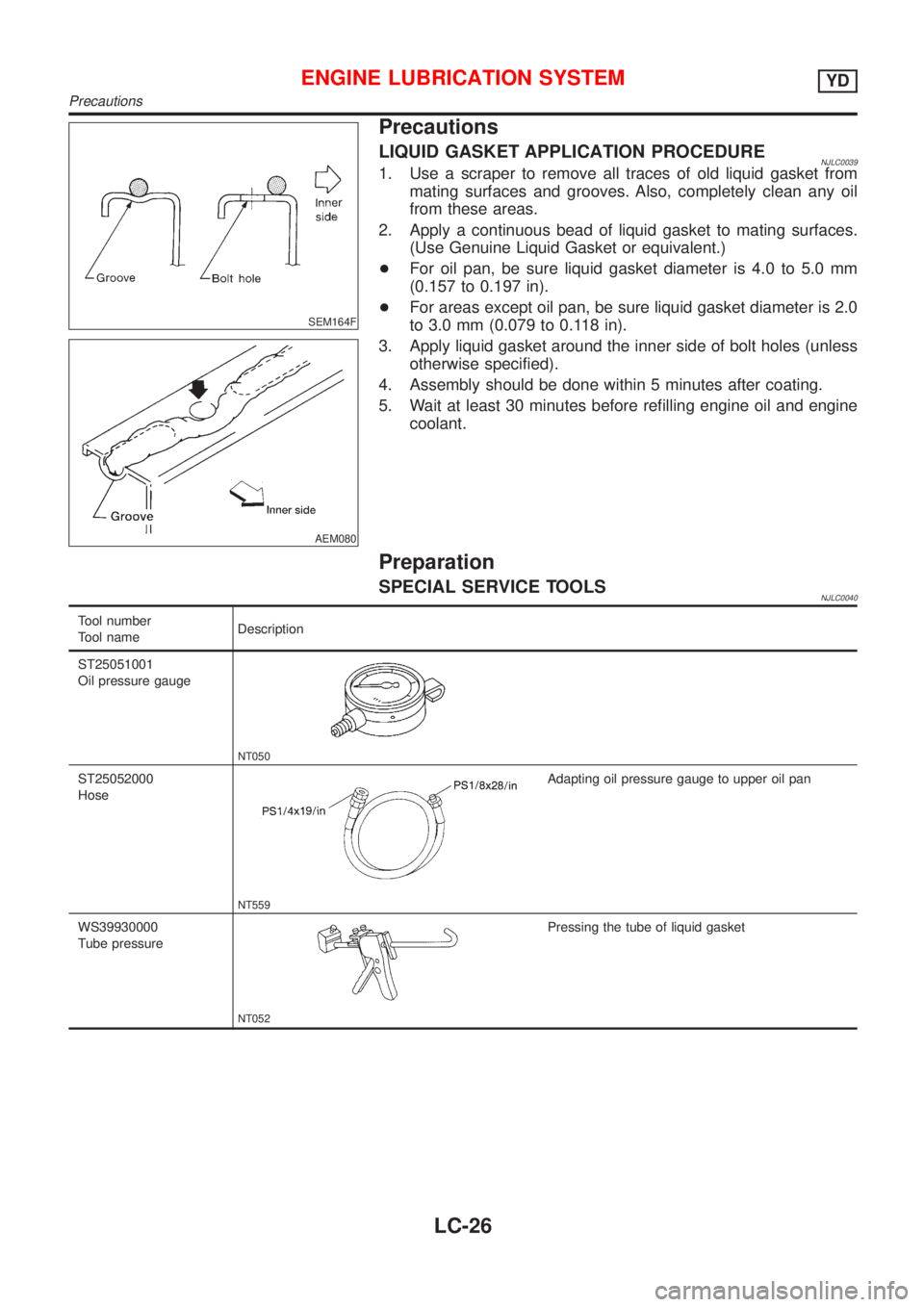
LIQUID GASKET APPLICATION PROCEDURENJLC00391. Use a scraper to remove all traces of old liquid gasket from
mating surfaces and grooves. Also, completely clean any oil
from these areas.
2. Apply a continuous bead of liquid gasket to mating surfaces.
(Use Genuine Liquid Gasket or equivalent.)
+For oil pan, be sure liquid gasket diameter is 4.0 to 5.0 mm
(0.157 to 0.197 in).
+For areas except oil pan, be sure liquid gasket diameter is 2.0
to 3.0 mm (0.079 to 0.118 in).
3. Apply liquid gasket around the inner side of bolt holes (unless
otherwise specified).
4. Assembly should be done within 5 minutes after coating.
5. Wait at least 30 minutes before refilling engine oil and engine
coolant.
Preparation
SPECIAL SERVICE TOOLSNJLC0040
Tool number
Tool nameDescription
ST25051001
Oil pressure gauge
NT050
ST25052000
Hose
NT559
Adapting oil pressure gauge to upper oil pan
WS39930000
Tube pressure
NT052
Pressing the tube of liquid gasket
ENGINE LUBRICATION SYSTEMYD
Precautions
LC-26
Page 2533 of 2898
Lubrication CircuitNJLC0041
JLC315B
ENGINE LUBRICATION SYSTEMYD
Lubrication Circuit
LC-27