2001 NISSAN ALMERA key
[x] Cancel search: keyPage 2372 of 2898
voltage; open is further down the circuit than the relay.
no voltage; open is between SW1 and relay (point B).
5) Close the relay and probe at the solenoid.
voltage; open is further down the circuit than the solenoid.
no voltage; open is between relay and solenoid (point C).
Any powered circuit can be diagnosed using the approach in the
above example.
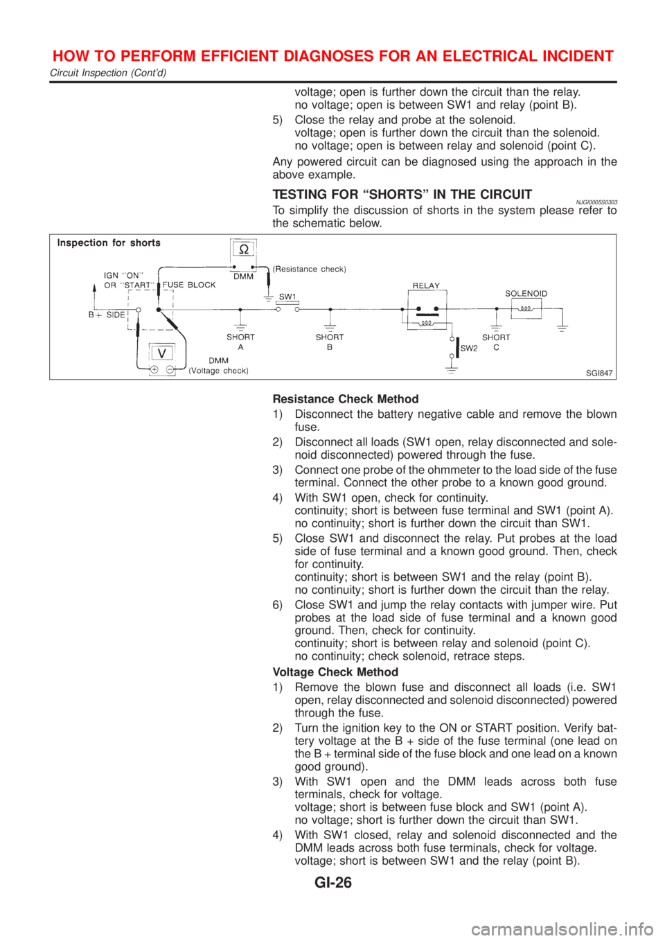
TESTING FOR ªSHORTSº IN THE CIRCUITNJGI0005S0303To simplify the discussion of shorts in the system please refer to
the schematic below.
SGI847
Resistance Check Method
1) Disconnect the battery negative cable and remove the blown
fuse.
2) Disconnect all loads (SW1 open, relay disconnected and sole-
noid disconnected) powered through the fuse.
3) Connect one probe of the ohmmeter to the load side of the fuse
terminal. Connect the other probe to a known good ground.
4) With SW1 open, check for continuity.
continuity; short is between fuse terminal and SW1 (point A).
no continuity; short is further down the circuit than SW1.
5) Close SW1 and disconnect the relay. Put probes at the load
side of fuse terminal and a known good ground. Then, check
for continuity.
continuity; short is between SW1 and the relay (point B).
no continuity; short is further down the circuit than the relay.
6) Close SW1 and jump the relay contacts with jumper wire. Put
probes at the load side of fuse terminal and a known good
ground. Then, check for continuity.
continuity; short is between relay and solenoid (point C).
no continuity; check solenoid, retrace steps.
Voltage Check Method
1) Remove the blown fuse and disconnect all loads (i.e. SW1
open, relay disconnected and solenoid disconnected) powered
through the fuse.
2) Turn the ignition key to the ON or START position. Verify bat-
tery voltage at the B + side of the fuse terminal (one lead on
the B + terminal side of the fuse block and one lead on a known
good ground).
3) With SW1 open and the DMM leads across both fuse
terminals, check for voltage.
voltage; short is between fuse block and SW1 (point A).
no voltage; short is further down the circuit than SW1.
4) With SW1 closed, relay and solenoid disconnected and the
DMM leads across both fuse terminals, check for voltage.
voltage; short is between SW1 and the relay (point B).
HOW TO PERFORM EFFICIENT DIAGNOSES FOR AN ELECTRICAL INCIDENT
Circuit Inspection (Cont'd)
GI-26
Page 2378 of 2898
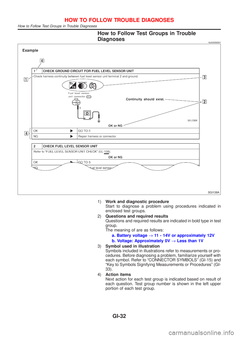
How to Follow Test Groups in Trouble
Diagnoses
NJGI0006S01
SGI138A
1)Work and diagnostic procedure
Start to diagnose a problem using procedures indicated in
enclosed test groups.
2)Questions and required results
Questions and required results are indicated in bold type in test
group.
The meaning of are as follows:
a. Battery voltage®11 - 14V or approximately 12V
b. Voltage: Approximately 0V®Less than 1V
3)Symbol used in illustration
Symbols included in illustrations refer to measurements or pro-
cedures. Before diagnosing a problem, familiarize yourself with
each symbol. Refer to ªCONNECTOR SYMBOLSº (GI-15) and
ªKey to Symbols Signifying Measurements or Proceduresº (GI-
33).
4)Action items
Next action for each test group is indicated based on result of
each question. Test group number is shown in the left upper
portion of each test group.
HOW TO FOLLOW TROUBLE DIAGNOSES
How to Follow Test Groups in Trouble Diagnoses
GI-32
Page 2379 of 2898
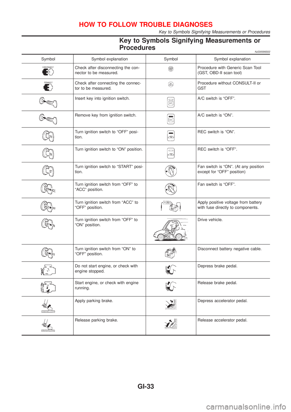
Key to Symbols Signifying Measurements or
Procedures
NJGI0006S02
Symbol Symbol explanation Symbol Symbol explanation
Check after disconnecting the con-
nector to be measured.Procedure with Generic Scan Tool
(GST, OBD-II scan tool)
Check after connecting the connec-
tor to be measured.Procedure without CONSULT-II or
GST
Insert key into ignition switch.A/C switch is ªOFFº.
Remove key from ignition switch.A/C switch is ªONº.
Turn ignition switch to ªOFFº posi-
tion.REC switch is ªONº.
Turn ignition switch to ªONº position.REC switch is ªOFFº.
Turn ignition switch to ªSTARTº posi-
tion.Fan switch is ªONº. (At any position
except for ªOFFº position)
Turn ignition switch from ªOFFº to
ªACCº position.Fan switch is ªOFFº.
Turn ignition switch from ªACCº to
ªOFFº position.Apply positive voltage from battery
with fuse directly to components.
Turn ignition switch from ªOFFº to
ªONº position.Drive vehicle.
Turn ignition switch from ªONº to
ªOFFº position.Disconnect battery negative cable.
Do not start engine, or check with
engine stopped.Depress brake pedal.
Start engine, or check with engine
running.Release brake pedal.
Apply parking brake.Depress accelerator pedal.
Release parking brake.Release accelerator pedal.
HOW TO FOLLOW TROUBLE DIAGNOSES
Key to Symbols Signifying Measurements or Procedures
GI-33
Page 2380 of 2898
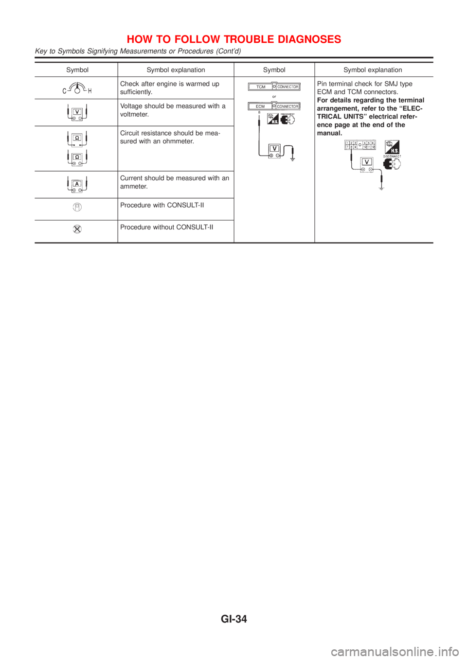
Symbol Symbol explanation Symbol Symbol explanation
Check after engine is warmed up
sufficiently.Pin terminal check for SMJ type
ECM and TCM connectors.
For details regarding the terminal
arrangement, refer to the ªELEC-
TRICAL UNITSº electrical refer-
ence page at the end of the
manual.
Voltage should be measured with a
voltmeter.
Circuit resistance should be mea-
sured with an ohmmeter.
Current should be measured with an
ammeter.
Procedure with CONSULT-II
Procedure without CONSULT-II
HOW TO FOLLOW TROUBLE DIAGNOSES
Key to Symbols Signifying Measurements or Procedures (Cont'd)
GI-34
Page 2381 of 2898
NJGI0007
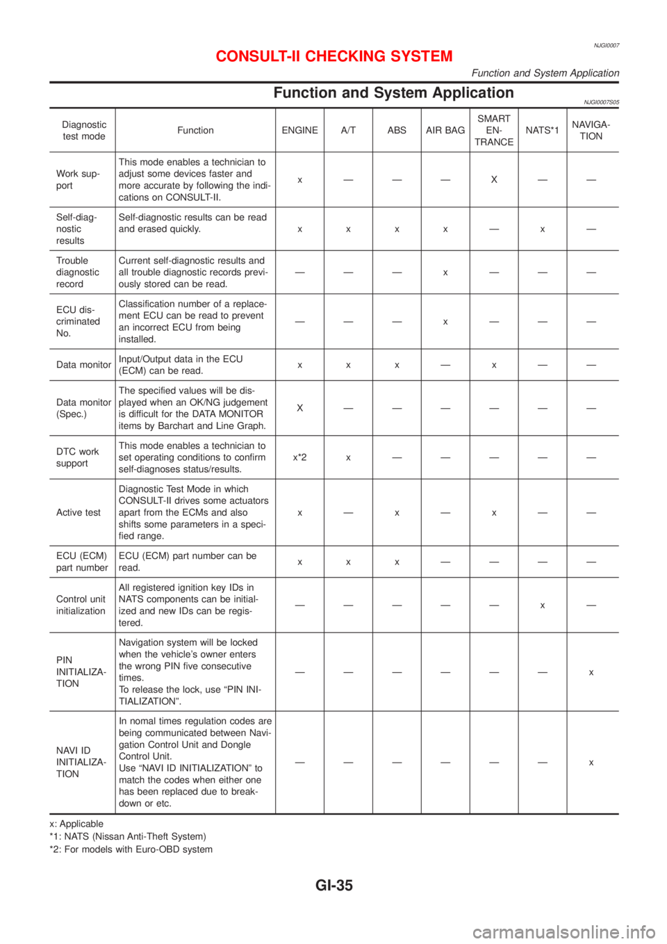
Function and System ApplicationNJGI0007S05
Diagnostic
test modeFunction ENGINE A/T ABS AIR BAGSMART
EN-
TRANCENATS*1NAVIGA-
TION
Work sup-
portThis mode enables a technician to
adjust some devices faster and
more accurate by following the indi-
cations on CONSULT-II.x ÐÐÐXÐÐ
Self-diag-
nostic
resultsSelf-diagnostic results can be read
and erased quickly.x x x xÐxÐ
Trouble
diagnostic
recordCurrent self-diagnostic results and
all trouble diagnostic records previ-
ously stored can be read.ÐÐÐ x ÐÐÐ
ECU dis-
criminated
No.Classification number of a replace-
ment ECU can be read to prevent
an incorrect ECU from being
installed.ÐÐÐ x ÐÐÐ
Data monitorInput/Output data in the ECU
(ECM) can be read.x x xÐxÐÐ
Data monitor
(Spec.)The specified values will be dis-
played when an OK/NG judgement
is difficult for the DATA MONITOR
items by Barchart and Line Graph.X ÐÐÐÐÐÐ
DTC work
supportThis mode enables a technician to
set operating conditions to confirm
self-diagnoses status/results.x*2x ÐÐÐÐÐ
Active testDiagnostic Test Mode in which
CONSULT-II drives some actuators
apart from the ECMs and also
shifts some parameters in a speci-
fied range.xÐxÐxÐÐ
ECU (ECM)
part numberECU (ECM) part number can be
read.x x x ÐÐÐÐ
Control unit
initializationAll registered ignition key IDs in
NATS components can be initial-
ized and new IDs can be regis-
tered.ÐÐÐÐÐ x Ð
PIN
INITIALIZA-
TIONNavigation system will be locked
when the vehicle's owner enters
the wrong PIN five consecutive
times.
To release the lock, use ªPIN INI-
TIALIZATIONº.ÐÐÐÐÐÐ x
NAVI ID
INITIALIZA-
TIONIn nomal times regulation codes are
being communicated between Navi-
gation Control Unit and Dongle
Control Unit.
Use ªNAVI ID INITIALIZATIONº to
match the codes when either one
has been replaced due to break-
down or etc.ÐÐÐÐÐÐ x
x: Applicable
*1: NATS (Nissan Anti-Theft System)
*2: For models with Euro-OBD system
CONSULT-II CHECKING SYSTEM
Function and System Application
GI-35
Page 2503 of 2898

Headlining - See Roof trim ........................ BT-43
Heated oxygen sensor (HO2S)
(front) .......... EC-216, 224, 230, 236, 245, 450
Heated oxygen sensor (HO2S) heater
(front) ........................................... EC-252, 457
Heated oxygen sensor (HO2S) heater
(rear) ............................................ EC-291, 469
Heated oxygen sensor (rear) ......... EC-258, 267,
275, 284, 462
Heated seat ............................................. EL-288
Height (Dimensions) ................................... GI-43
High clutch ............................................... AT-407
Hood ............................................................ BT-7
Horn ......................................................... EL-234
How to erase DTC for OBD system .. EC-70, 73,
627
I
IACV-AAC valve .............................. EC-376, 511
IATS - Wiring diagram .................... EC-196, 444
IGN/SG - Wiring diagram ........................ EC-548
ILL - Wiring diagram ................................ EL-112
INJECT - Wiring diagram ........................ EC-542
INT/L - Wiring diagram .................... EL-141, 143
IVC - Wiring diagram ...................... EC-395, 527
Identification plate ...................................... GI-40
Idle air control (IAC) system ........... EC-376, 511
Idle air control valve (IACV) ............ EC-376, 511
Idle speed ......................................... EC-43, 641
Ignition timing ............................................ EC-43
Illumination ............................................... EL-108
Injection nozzle ....................................... EC-614
Injector removal and installation ............... EC-41
Input shaft (FF M/T) ............... MT-36, 64, 93, 98
Instrument panel ........................................ BT-25
Intake air temperature sensor ......... EC-194, 442
Intake valve timing control solenoid
valve ............................................ EC-393, 526
Interior lamp on-off control .............. EL-116, 128
Interior lamp ............................................. EL-115
Interior ........................................................ BT-31
J
Jacking points ............................................ GI-45
Joint connector (J/C) ............................... EL-583
Junction box (J/B) .................................... EL-577
K
Keyless entry system - See Multi-remote control
system ..................................................... EL-392
Knock sensor (KS) .......................... EC-324, 325
Knuckle spindle ........................................... AX-5
L
LOAD - Wiring diagram .......................... EC-579
Length (Dimensions) .................................. GI-43
License lamp ............................................. EL-81
Lifting points ............................................... GI-46
Line pressure solenoid valve ................... AT-232
Line pressure test (A/T) ............................. AT-84
Liquid gasket application ...................... EM-4, 77
Location of electrical units ....................... EL-517
Lock, door .................................................. BT-21
Low and reverse brake ............................ AT-419
Lubricant (R134a) A/C .............................. HA-80
Lubricants ................................................. MA-16
Lubrication circuit (engine) .................... LC-4, 27
M
M/T major overhaul ....................... MT-30, 54, 92
M/T removal and installation ..................... MT-23
MAFS - Wiring diagram .................. EC-189, 673
MAIN - Wiring diagram ................... EC-178, 666
MAJOR OVERHALL ................................ AT-357
METER - Wiring diagram ........................ EL-151
MIL & Data link connectors circuit .......... EC-591
MIL/DL - Wiring diagram ................. EC-591, 831
MIRROR - Wiring diagram .............. EL-294, 295
Magnet clutch ............................................ HA-83
Mainshaft (M/T) .................... MT-39, 69, 93, 103
Malfunction indicator lamp (MIL) ...... EC-74, 628
Manual air conditioner - Wiring
diagram .................................................. HA-27
Manual transaxle number .......................... GI-42
Mass air flow sensor (MAFS) ......... EC-187, 673
Master cylinder (brake) ............................. BR-14
Master cylinder (clutch) ............................. CL-11
Meter ........................................................ EL-144
Mirror defogger ........................................ EL-240
Mirror, door ................................................ BT-75
Misfire ...................................................... EC-318
Mode door control linkage
adjustment ............................................. HA-41
Model variation ........................................... GI-38
Molding - See Exterior ............................... BT-47
Multi-remote control system .................... EL-392
Multiport fuel injection (MFI) system ......... EC-32
Multiport fuel injection precautions ............... GI-6
N
NATS (Nissan Anti-theft System)
precautions ................................................... GI-3
NATS (Nissan Anti-theft System) ............ EL-422
NATS - Wiring diagram ................... EL-425, 427
NVH troubleshooting (AX) ........................... AX-3
NVH troubleshooting (BR) .......................... BR-7
NVH troubleshooting (MT) ........................ MT-13
NVH troubleshooting (ST) ........................... ST-5
ALPHABETICAL INDEX
IDX-5
Page 2556 of 2898
NJMA0036
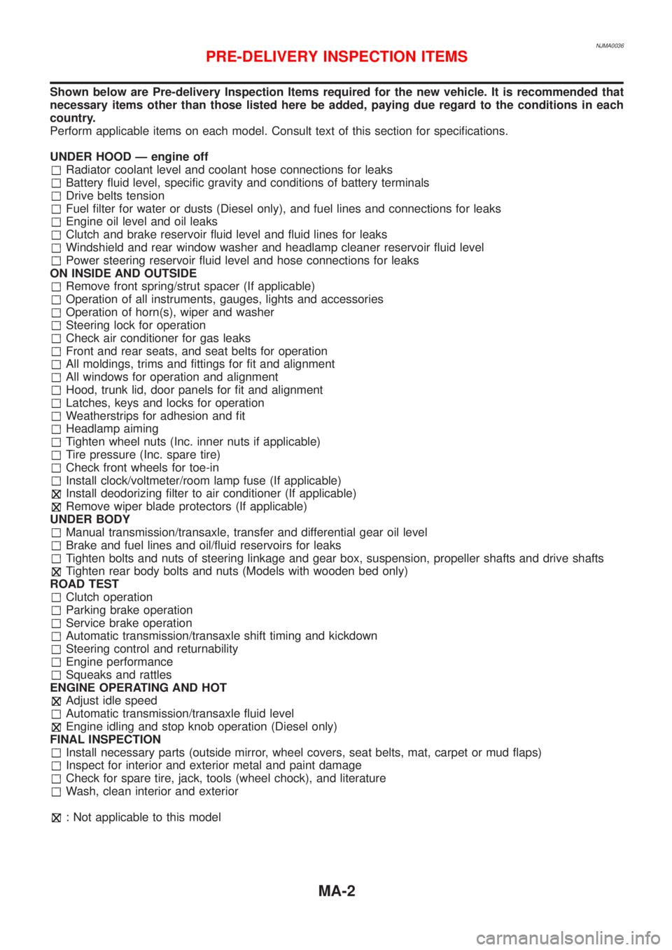
Shown below are Pre-delivery Inspection Items required for the new vehicle. It is recommended that
necessary items other than those listed here be added, paying due regard to the conditions in each
country.
Perform applicable items on each model. Consult text of this section for specifications.
UNDER HOOD Ð engine off
Radiator coolant level and coolant hose connections for leaks
Battery fluid level, specific gravity and conditions of battery terminals
Drive belts tension
Fuel filter for water or dusts (Diesel only), and fuel lines and connections for leaks
Engine oil level and oil leaks
Clutch and brake reservoir fluid level and fluid lines for leaks
Windshield and rear window washer and headlamp cleaner reservoir fluid level
Power steering reservoir fluid level and hose connections for leaks
ON INSIDE AND OUTSIDE
Remove front spring/strut spacer (If applicable)
Operation of all instruments, gauges, lights and accessories
Operation of horn(s), wiper and washer
Steering lock for operation
Check air conditioner for gas leaks
Front and rear seats, and seat belts for operation
All moldings, trims and fittings for fit and alignment
All windows for operation and alignment
Hood, trunk lid, door panels for fit and alignment
Latches, keys and locks for operation
Weatherstrips for adhesion and fit
Headlamp aiming
Tighten wheel nuts (Inc. inner nuts if applicable)
Tire pressure (Inc. spare tire)
Check front wheels for toe-in
Install clock/voltmeter/room lamp fuse (If applicable)
Install deodorizing filter to air conditioner (If applicable)
Remove wiper blade protectors (If applicable)
UNDER BODY
Manual transmission/transaxle, transfer and differential gear oil level
Brake and fuel lines and oil/fluid reservoirs for leaks
Tighten bolts and nuts of steering linkage and gear box, suspension, propeller shafts and drive shafts
Tighten rear body bolts and nuts (Models with wooden bed only)
ROAD TEST
Clutch operation
Parking brake operation
Service brake operation
Automatic transmission/transaxle shift timing and kickdown
Steering control and returnability
Engine performance
Squeaks and rattles
ENGINE OPERATING AND HOT
Adjust idle speed
Automatic transmission/transaxle fluid level
Engine idling and stop knob operation (Diesel only)
FINAL INSPECTION
Install necessary parts (outside mirror, wheel covers, seat belts, mat, carpet or mud flaps)
Inspect for interior and exterior metal and paint damage
Check for spare tire, jack, tools (wheel chock), and literature
Wash, clean interior and exterior
: Not applicable to this model
PRE-DELIVERY INSPECTION ITEMS
MA-2
Page 2733 of 2898
SRS797-A
Maintenance ItemsNJRS0012CAUTION:
Do not use electrical test equipment to check SRS circuit.
1. Check operation of ªAIR BAGº warning lamp.
After turning ignition key to ªONº position, ªAIR BAGº warning
lamp illuminates. The ªAIR BAGº warning lamp will go off after
about 7 seconds if no malfunction is detected. If any of the fol-
lowing ªAIR BAGº warning lamp conditions occur, immediately
check the air bag system. Refer to RS-59 for details.
+The ªAIR BAGº warning lamp does not illuminate when the
ignition switch is turned ªONº.
+The ªAIR BAGº warning lamp does not go off about 7 seconds
after the ignition switch is turned ªONº.
+The ªAIR BAGº warning lamp blinks after about 7 seconds after
the ignition switch is turned ªONº.
2. Visually check SRS components.
1) Diagnosis sensor unit
+Check diagnosis sensor unit and bracket for dents, cracks and
deformities.
+Check connectors for damage, and terminals for deformities.
2) Air bag module and steering wheel
+Remove air bag module from steering wheel, instrument panel
or seatback. Check harness cover and connectors for damage,
terminals for deformities, and harness for binding.
+Install driver air bag module to steering wheel to check fit or
alignment with the wheel.
+Check steering wheel for excessive free play.
+Install front passenger air bag module to instrument panel to
check fit or alignment with the instrument panel.
+Install front side air bag module to seatback to check fit and
alignment with the seat.
3) Spiral cable
+Check spiral cable for dents, cracks, or deformities.
+Check connectors and protective tape for damage.
+Check steering wheel for noise, binding or heavy operation.
4) Main harness, body harness, side air bag module sub-harness
+Check connectors for poor connections, damage, and termi-
nals for deformities.
+Check harnesses for binding, chafing or cut.
5) Front seat belt pre-tensioner
+Check harness cover and connectors for damage, terminals
for deformities, and harness for binding.
+Check belts for damage and anchors for loose mounting.
+Check retractor for smooth operation.
+Perform self-diagnosis for seat belt pre-tensioner using ªAIR
BAGº warning lamp or CONSULT-II.
Refer to ªSRS Operation Checkº for details. (RS-59)
6) Side air bag (satellite) sensor
+Check side air bag (satellite) sensor (including bracket portion)
for dents, cracks or deformities.
+Check connectors for damage, and terminals for deformities.
CAUTION:
Replace previously used special bolts, hex bolts and ground
bolt with new ones.
SUPPLEMENTAL RESTRAINT SYSTEM (SRS)
Maintenance Items
RS-25