2001 NISSAN ALMERA key
[x] Cancel search: keyPage 2188 of 2898
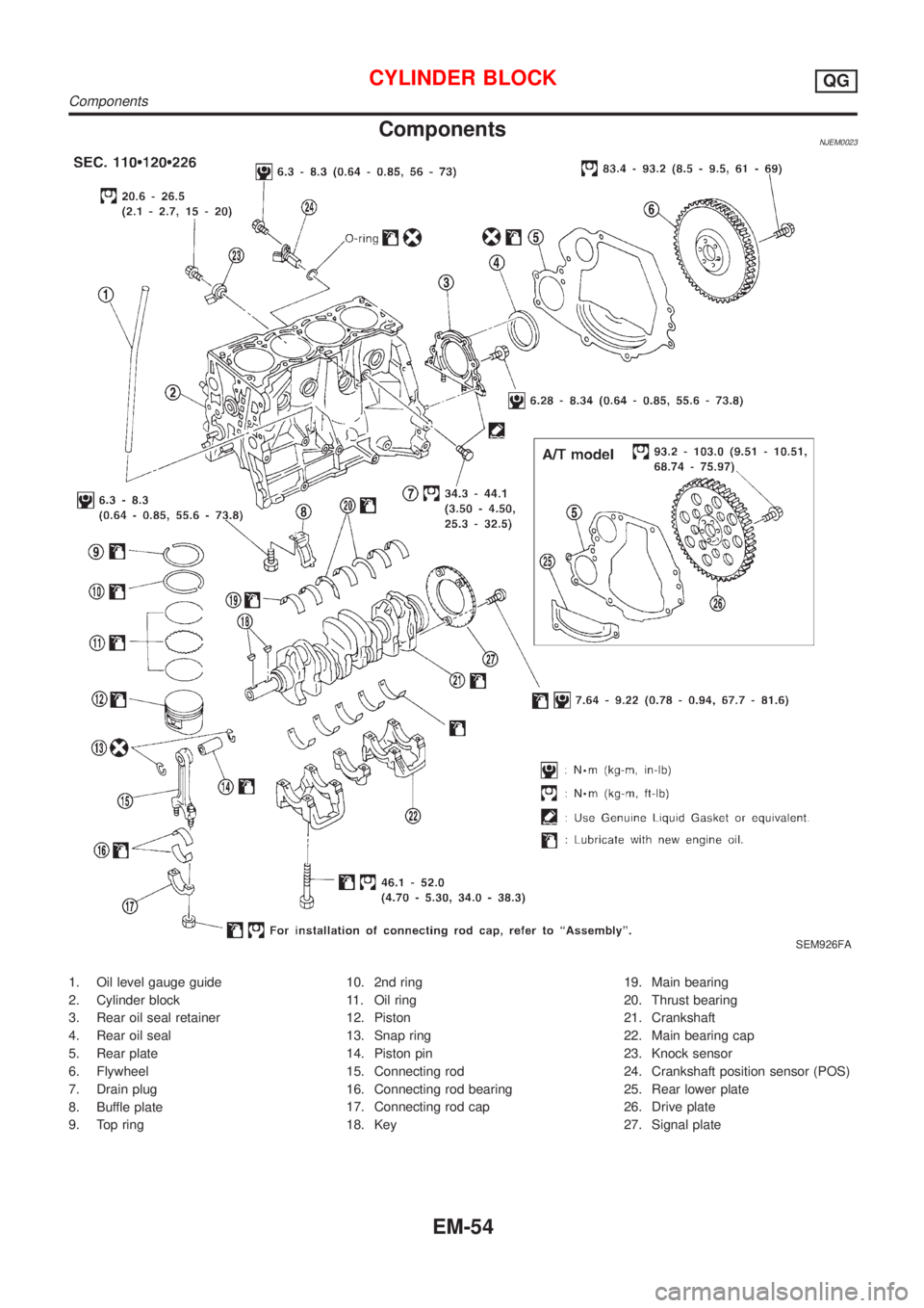
ComponentsNJEM0023
SEM926FA
1. Oil level gauge guide
2. Cylinder block
3. Rear oil seal retainer
4. Rear oil seal
5. Rear plate
6. Flywheel
7. Drain plug
8. Buffle plate
9. Top ring10. 2nd ring
11. Oil ring
12. Piston
13. Snap ring
14. Piston pin
15. Connecting rod
16. Connecting rod bearing
17. Connecting rod cap
18. Key19. Main bearing
20. Thrust bearing
21. Crankshaft
22. Main bearing cap
23. Knock sensor
24. Crankshaft position sensor (POS)
25. Rear lower plate
26. Drive plate
27. Signal plate
CYLINDER BLOCKQG
Components
EM-54
Page 2238 of 2898
JEM137G
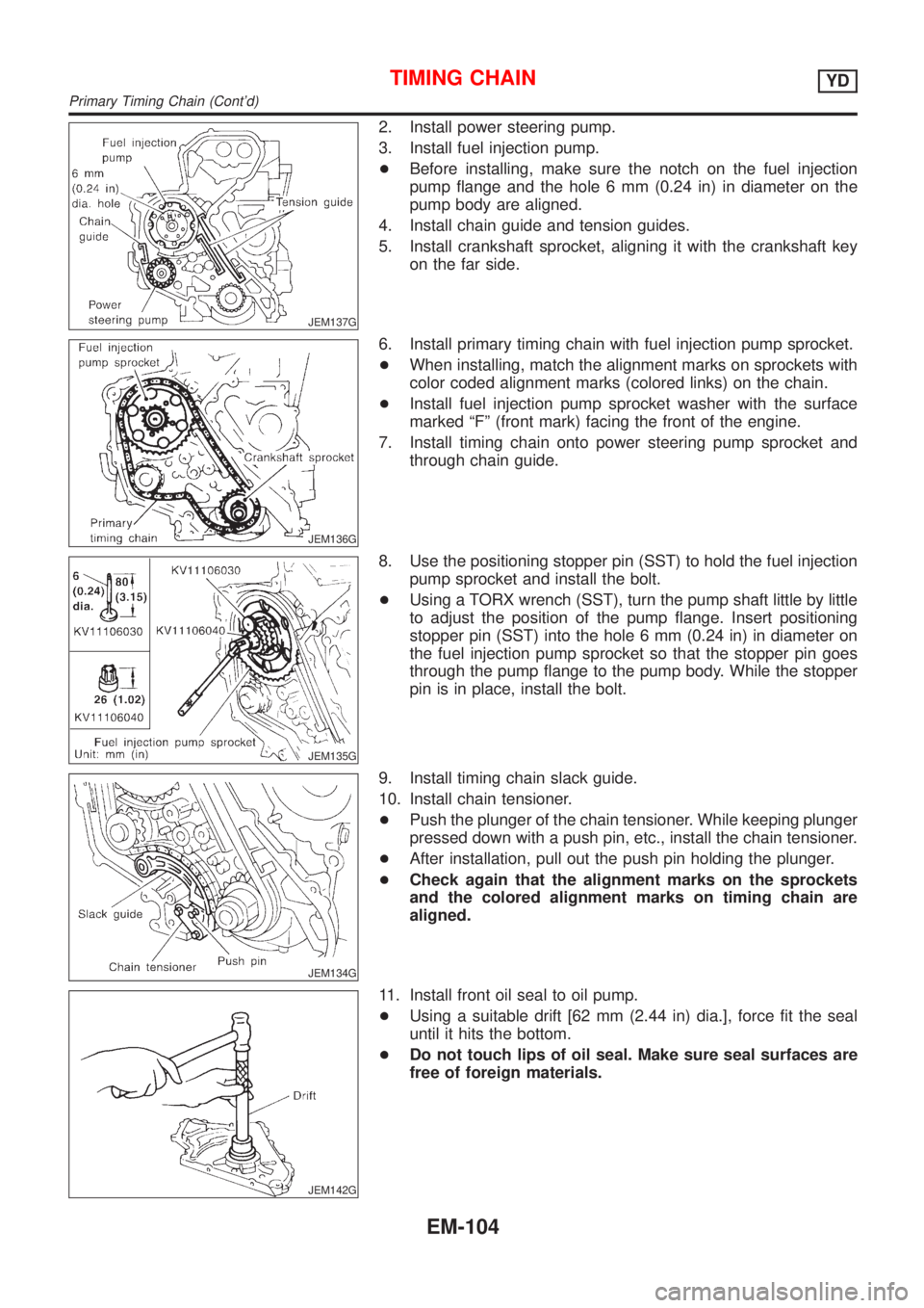
2. Install power steering pump.
3. Install fuel injection pump.
+Before installing, make sure the notch on the fuel injection
pump flange and the hole 6 mm (0.24 in) in diameter on the
pump body are aligned.
4. Install chain guide and tension guides.
5. Install crankshaft sprocket, aligning it with the crankshaft key
on the far side.
JEM136G
6. Install primary timing chain with fuel injection pump sprocket.
+When installing, match the alignment marks on sprockets with
color coded alignment marks (colored links) on the chain.
+Install fuel injection pump sprocket washer with the surface
marked ªFº (front mark) facing the front of the engine.
7. Install timing chain onto power steering pump sprocket and
through chain guide.
JEM135G
8. Use the positioning stopper pin (SST) to hold the fuel injection
pump sprocket and install the bolt.
+Using a TORX wrench (SST), turn the pump shaft little by little
to adjust the position of the pump flange. Insert positioning
stopper pin (SST) into the hole 6 mm (0.24 in) in diameter on
the fuel injection pump sprocket so that the stopper pin goes
through the pump flange to the pump body. While the stopper
pin is in place, install the bolt.
JEM134G
9. Install timing chain slack guide.
10. Install chain tensioner.
+Push the plunger of the chain tensioner. While keeping plunger
pressed down with a push pin, etc., install the chain tensioner.
+After installation, pull out the push pin holding the plunger.
+Check again that the alignment marks on the sprockets
and the colored alignment marks on timing chain are
aligned.
JEM142G
11. Install front oil seal to oil pump.
+Using a suitable drift [62 mm (2.44 in) dia.], force fit the seal
until it hits the bottom.
+Do not touch lips of oil seal. Make sure seal surfaces are
free of foreign materials.
TIMING CHAINYD
Primary Timing Chain (Cont'd)
EM-104
Page 2326 of 2898
SEF122U
Checking Water in Fuel Filter Sensor (where
fitted)
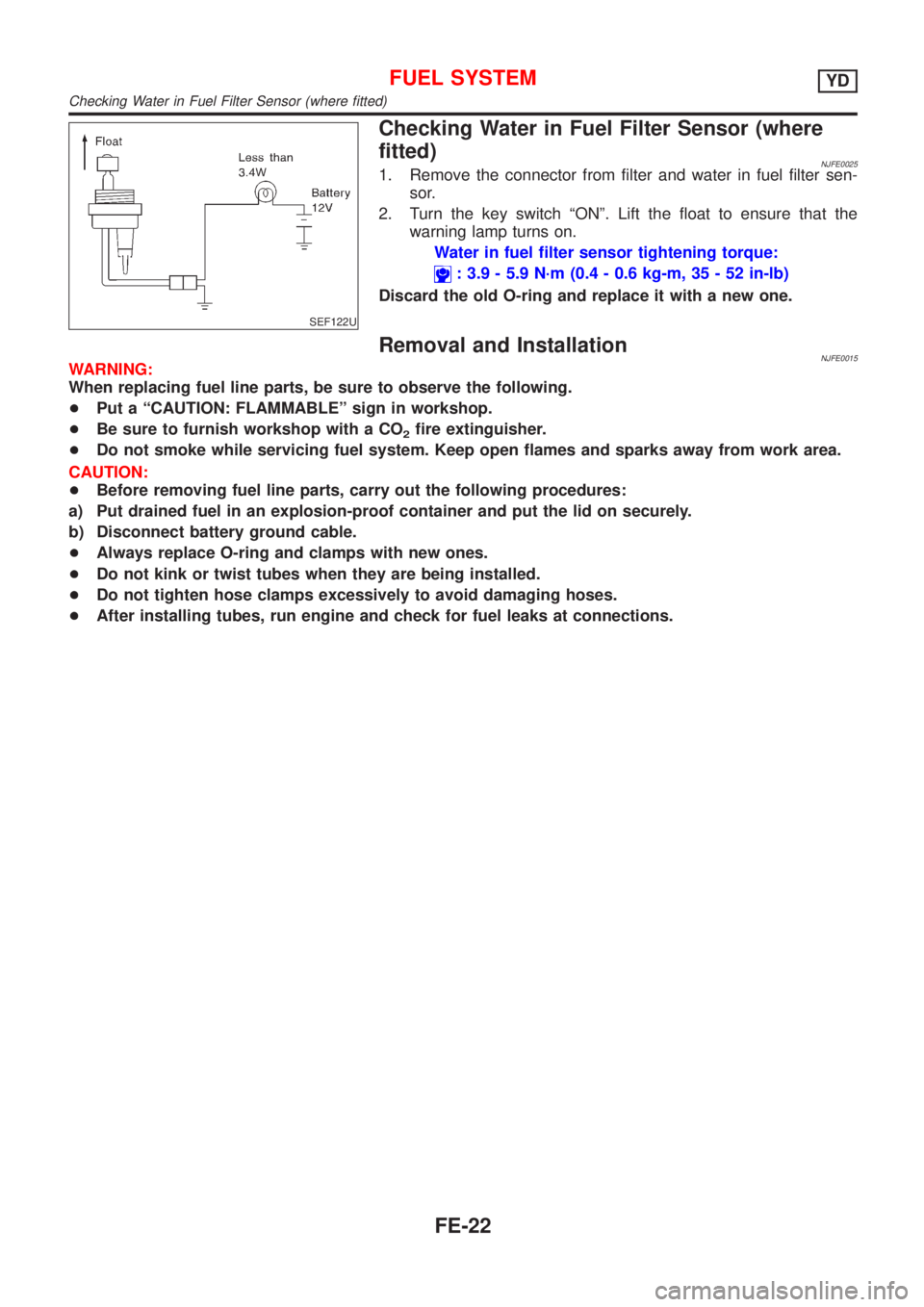
NJFE00251. Remove the connector from filter and water in fuel filter sen-
sor.
2. Turn the key switch ªONº. Lift the float to ensure that the
warning lamp turns on.
Water in fuel filter sensor tightening torque:
: 3.9 - 5.9 N´m (0.4 - 0.6 kg-m, 35 - 52 in-lb)
Discard the old O-ring and replace it with a new one.
Removal and InstallationNJFE0015WARNING:
When replacing fuel line parts, be sure to observe the following.
+Put a ªCAUTION: FLAMMABLEº sign in workshop.
+Be sure to furnish workshop with a CO
2fire extinguisher.
+Do not smoke while servicing fuel system. Keep open flames and sparks away from work area.
CAUTION:
+Before removing fuel line parts, carry out the following procedures:
a) Put drained fuel in an explosion-proof container and put the lid on securely.
b) Disconnect battery ground cable.
+Always replace O-ring and clamps with new ones.
+Do not kink or twist tubes when they are being installed.
+Do not tighten hose clamps excessively to avoid damaging hoses.
+After installing tubes, run engine and check for fuel leaks at connections.
FUEL SYSTEMYD
Checking Water in Fuel Filter Sensor (where fitted)
FE-22
Page 2347 of 2898
GENERAL INFORMATION
SECTION
GI
CONTENTS
PRECAUTIONS...............................................................3
Precautions ..................................................................3
PRECAUTIONS FOR SUPPLEMENTAL
RESTRAINT SYSTEM (SRS)²AIR BAG²AND
²SEAT BELT PRE-TENSIONER²
.................................3
PRECAUTIONS FOR NATS (NISSAN ANTI-THEFT
SYSTEM)
..................................................................3
GENERAL PRECAUTIONS.........................................4
PRECAUTIONS FOR MULTIPORT FUEL
INJECTION SYSTEM OR ENGINE CONTROL
SYSTEM
...................................................................6
PRECAUTIONS FOR THREE WAY CATALYST...........6
PRECAUTIONS FOR HOSES.....................................6
PRECAUTIONS FOR ENGINE OILS...........................7
PRECAUTIONS FOR FUEL........................................8
PRECAUTIONS FOR AIR CONDITIONING..................8
HOW TO USE THIS MANUAL........................................9
HOW TO READ WIRING DIAGRAMS.......................... 11
Sample/Wiring Diagram - EXAMPL - ........................ 11
OPTIONAL SPLICE..................................................12
Description .................................................................13
CONNECTOR SYMBOLS.........................................15
HARNESS INDICATION...........................................16
COMPONENT INDICATION......................................16
SWITCH POSITIONS...............................................16
DETECTABLE LINES AND NON-DETECTABLE
LINES
.....................................................................17
MULTIPLE SWITCH.................................................18
REFERENCE AREA.................................................19
HOW TO PERFORM EFFICIENT DIAGNOSES
FOR AN ELECTRICAL INCIDENT...............................21
Work Flow ..................................................................21
Incident Simulation Tests ...........................................22
INTRODUCTION......................................................22
VEHICLE VIBRATION..............................................22
HEAT SENSITIVE....................................................23
FREEZING..............................................................23
WATER INTRUSION................................................24
ELECTRICAL LOAD.................................................24
COLD OR HOT START UP.......................................24
Circuit Inspection .......................................................24
INTRODUCTION......................................................24
TESTING FOR²OPENS²IN THE CIRCUIT................25
TESTING FOR²SHORTS²IN THE CIRCUIT..............26
GROUND INSPECTION...........................................27
VOLTAGE DROP TESTS..........................................27
CONTROL UNIT CIRCUIT TEST...............................29
HOW TO FOLLOW TROUBLE DIAGNOSES...............31
How to Follow Test Groups in Trouble Diagnoses ....32
Key to Symbols Signifying Measurements or
Procedures.................................................................33
CONSULT-II CHECKING SYSTEM...............................35
Function and System Application ..............................35
Nickel Metal Hydride Battery Replacement...............36
Checking Equipment..................................................36
CONSULT-II Data Link Connector (DLC) Circuit ......37
INSPECTION PROCEDURE.....................................37
IDENTIFICATION INFORMATION................................38
Model Variation ..........................................................38
PREFIX AND SUFFIX DESIGNATIONS.....................39
Identification Number .................................................39
VEHICLE IDENTIFICATION NUMBER
ARRANGEMENT
.....................................................40
IDENTIFICATION PLATE..........................................40
ENGINE SERIAL NUMBER.......................................41
AUTOMATIC TRANSAXLE NUMBER........................41
MANUAL TRANSAXLE NUMBER..............................42
Dimensions ................................................................43
Wheels and Tires .......................................................43
LIFTING POINTS AND TOW TRUCK TOWING...........44
Preparation ................................................................44
SPECIAL SERVICE TOOLS......................................44
Board-on Lift ..............................................................44
Garage Jack and Safety Stand .................................45
2-pole Lift ...................................................................46
Tow Truck Towing ......................................................47
TOWING AN AUTOMATIC TRANSAXLE MODEL
WITH FOUR WHEELS ON GROUND
........................47
TOWING AN AUTOMATIC TRANSAXLE MODEL
WITH REAR WHEELS RAISED (WITH FRONT
WHEELS ON GROUND)
..........................................47
Page 2349 of 2898
PrecautionsNJGI0001Observe the following precautions to ensure safe and proper
servicing. These precautions are not described in each indi-
vidual section.
SGI646
PRECAUTIONS FOR SUPPLEMENTAL RESTRAINT
SYSTEM (SRS) ªAIR BAGº AND ªSEAT BELT
PRE-TENSIONERº
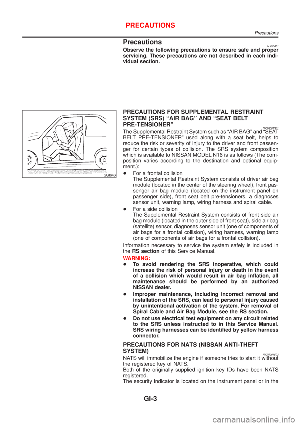
NJGI0001S01The Supplemental Restraint System such as ªAIR BAGº and ªSEAT
BELT PRE-TENSIONERº used along with a seat belt, helps to
reduce the risk or severity of injury to the driver and front passen-
ger for certain types of collision. The SRS system composition
which is available to NISSAN MODEL N16 is as follows (The com-
position varies according to the destination and optional equip-
ment.):
+For a frontal collision
The Supplemental Restraint System consists of driver air bag
module (located in the center of the steering wheel), front pas-
senger air bag module (located on the instrument panel on
passenger side), front seat belt pre-tensioners, a diagnoses
sensor unit, warning lamp, wiring harness and spiral cable.
+For a side collision
The Supplemental Restraint System consists of front side air
bag module (located in the outer side of front seat), side air bag
(satellite) sensor, diagnoses sensor unit (one of components of
air bags for a frontal collision), wiring harness, warning lamp
(one of components of air bags for a frontal collision).
Information necessary to service the system safely is included in
theRS sectionof this Service Manual.
WARNING:
+To avoid rendering the SRS inoperative, which could
increase the risk of personal injury or death in the event
of a collision which would result in air bag inflation, all
maintenance should be performed by an authorized
NISSAN dealer.
+Improper maintenance, including incorrect removal and
installation of the SRS, can lead to personal injury caused
by unintentional activation of the system. For removal of
Spiral Cable and Air Bag Module, see the RS section.
+Do not use electrical test equipment on any circuit related
to the SRS unless instructed to in this Service Manual.
SRS wiring harnesses can be identified by yellow harness
connector.
PRECAUTIONS FOR NATS (NISSAN ANTI-THEFT
SYSTEM)
NJGI0001S02NATS will immobilize the engine if someone tries to start it without
the registered key of NATS.
Both of the originally supplied ignition key IDs have been NATS
registered.
The security indicator is located on the instrument panel or in the
PRECAUTIONS
Precautions
GI-3
Page 2350 of 2898
combination meter. The indicator blinks when the ignition switch is
in ªOFFº or ªACCº position. Therefore, NATS warns outsiders that
the vehicle is equipped with the anti-theft system.
+When NATS detects trouble, the security indicator lamp lights
up while ignition switch is in ªONº position.
This lighting up indicates that the anti-theft is not functioning,
so prompt service is required.
+When servicing NATS (trouble diagnoses, system initialization
and additional registration of other NATS ignition key IDs),
CONSULT-II hardware and CONSULT-II NATS software is
necessary.
Regarding the procedures of NATS initialization and NATS
ignition key ID registration, refer to CONSULT-II operation
manual, NATS.
Therefore, CONSULT-II NATS software (program card and
operation manual) must be kept strictly confidential to main-
tain the integrity of the anti-theft function.
+When servicing NATS (trouble diagnoses, system initialization
and additional registration of other NATS ignition key IDs), it
may be necessary to re-register original key identification.
Therefore, be sure to receive all keys from vehicle owner. A
maximum of five key IDs can be registered into NATS.
+When failing to start the engine first time using the key of
NATS, start as follows.
a) Leave the ignition key in ªONº position for approximately 5
seconds.
b) Turn ignition key to ªOFFº or ªLOCKº position and wait approxi-
mately 5 seconds.
c) Repeat step 1 and 2 again.
d) Restart the engine while keeping the key separate from any
others on key-chain.
SGI285
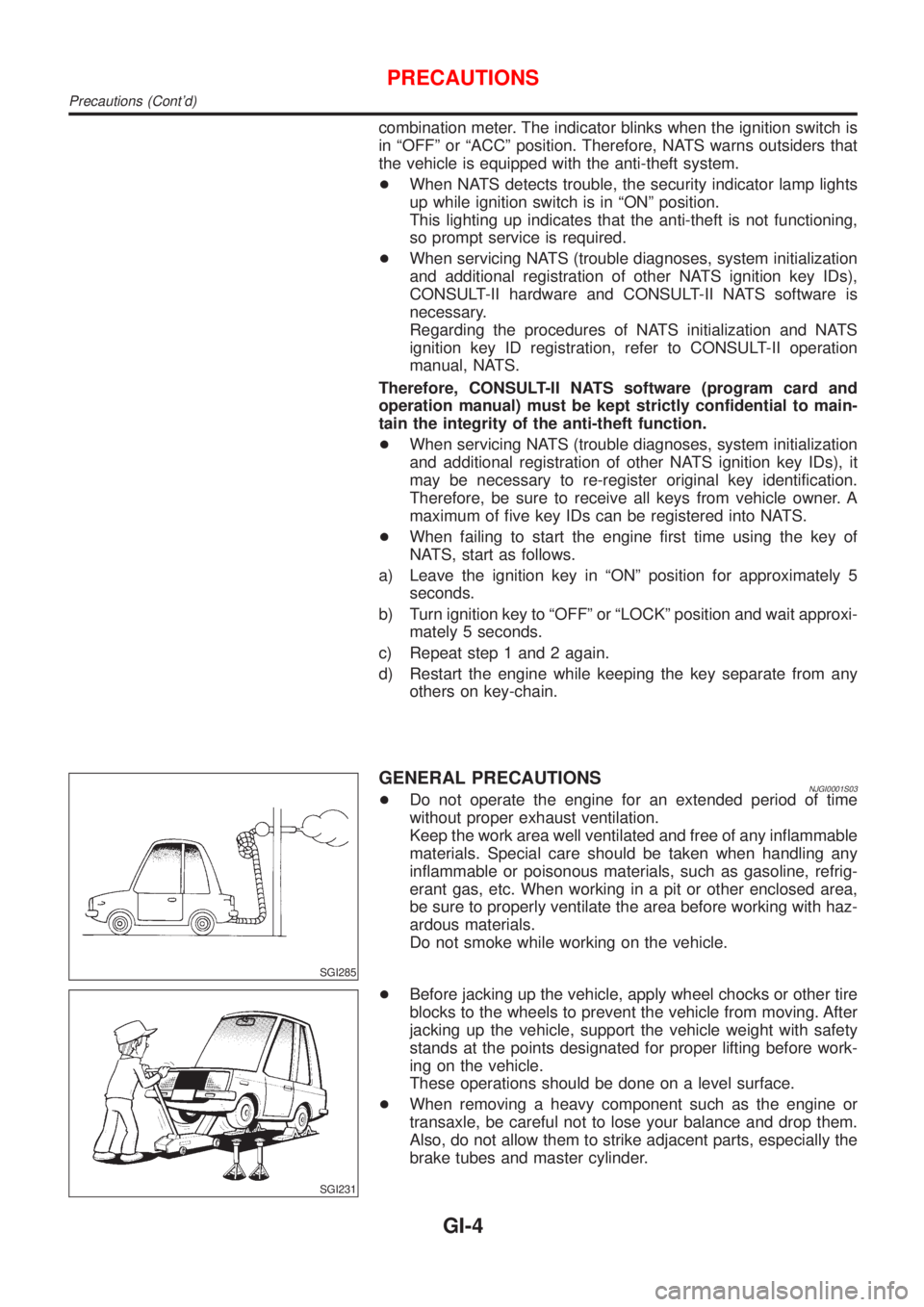
GENERAL PRECAUTIONSNJGI0001S03+Do not operate the engine for an extended period of time
without proper exhaust ventilation.
Keep the work area well ventilated and free of any inflammable
materials. Special care should be taken when handling any
inflammable or poisonous materials, such as gasoline, refrig-
erant gas, etc. When working in a pit or other enclosed area,
be sure to properly ventilate the area before working with haz-
ardous materials.
Do not smoke while working on the vehicle.
SGI231
+Before jacking up the vehicle, apply wheel chocks or other tire
blocks to the wheels to prevent the vehicle from moving. After
jacking up the vehicle, support the vehicle weight with safety
stands at the points designated for proper lifting before work-
ing on the vehicle.
These operations should be done on a level surface.
+When removing a heavy component such as the engine or
transaxle, be careful not to lose your balance and drop them.
Also, do not allow them to strike adjacent parts, especially the
brake tubes and master cylinder.
PRECAUTIONS
Precautions (Cont'd)
GI-4
Page 2351 of 2898
SEF289H
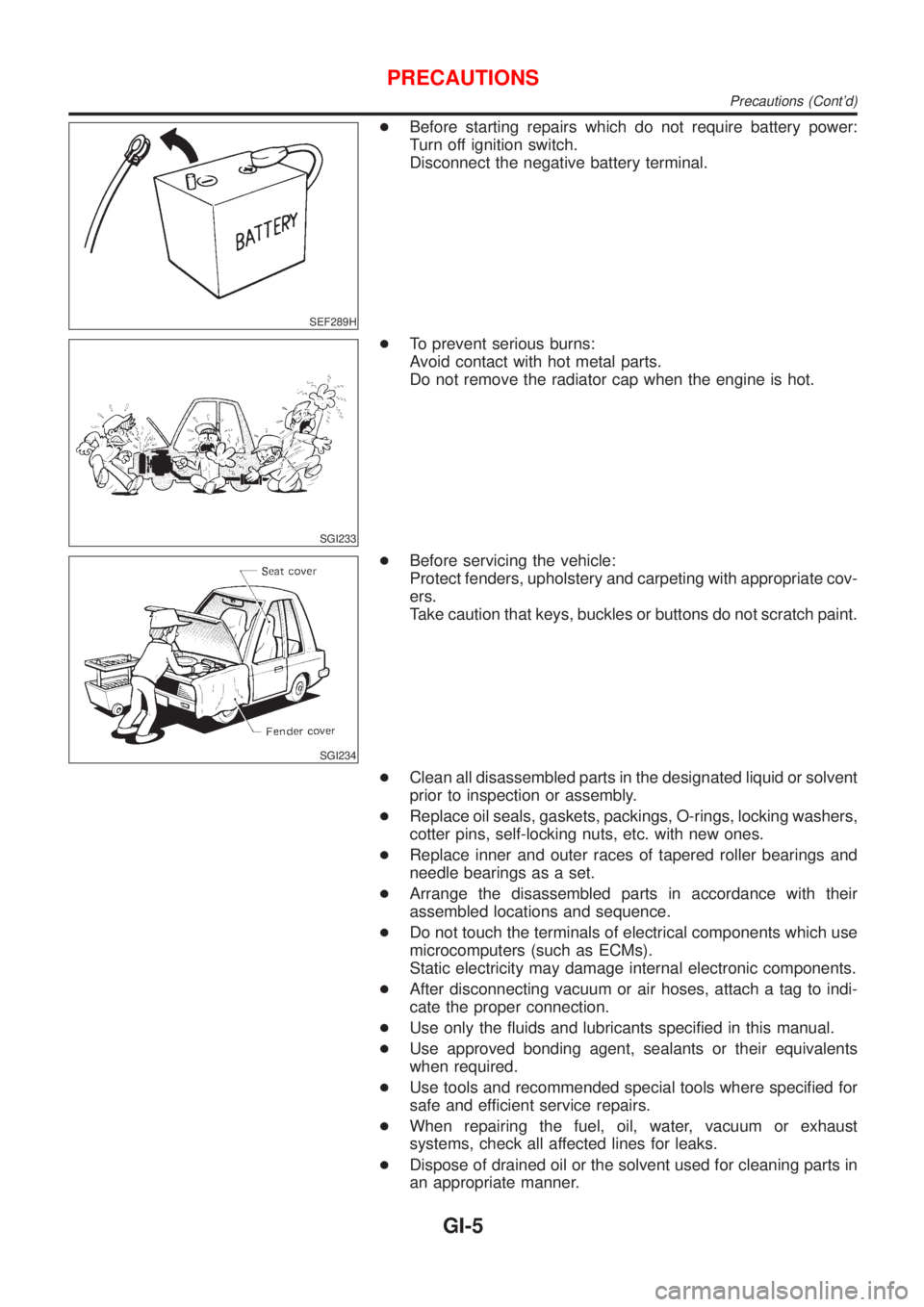
+Before starting repairs which do not require battery power:
Turn off ignition switch.
Disconnect the negative battery terminal.
SGI233
+To prevent serious burns:
Avoid contact with hot metal parts.
Do not remove the radiator cap when the engine is hot.
SGI234
+Before servicing the vehicle:
Protect fenders, upholstery and carpeting with appropriate cov-
ers.
Take caution that keys, buckles or buttons do not scratch paint.
+Clean all disassembled parts in the designated liquid or solvent
prior to inspection or assembly.
+Replace oil seals, gaskets, packings, O-rings, locking washers,
cotter pins, self-locking nuts, etc. with new ones.
+Replace inner and outer races of tapered roller bearings and
needle bearings as a set.
+Arrange the disassembled parts in accordance with their
assembled locations and sequence.
+Do not touch the terminals of electrical components which use
microcomputers (such as ECMs).
Static electricity may damage internal electronic components.
+After disconnecting vacuum or air hoses, attach a tag to indi-
cate the proper connection.
+Use only the fluids and lubricants specified in this manual.
+Use approved bonding agent, sealants or their equivalents
when required.
+Use tools and recommended special tools where specified for
safe and efficient service repairs.
+When repairing the fuel, oil, water, vacuum or exhaust
systems, check all affected lines for leaks.
+Dispose of drained oil or the solvent used for cleaning parts in
an appropriate manner.
PRECAUTIONS
Precautions (Cont'd)
GI-5
Page 2367 of 2898
NJGI0005
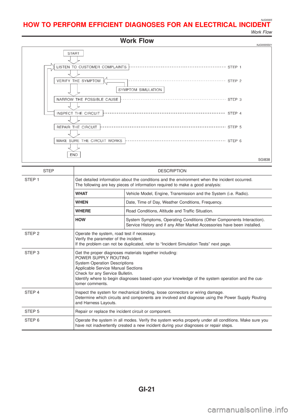
Work FlowNJGI0005S01
SGI838
STEP DESCRIPTION
STEP 1 Get detailed information about the conditions and the environment when the incident occurred.
The following are key pieces of information required to make a good analysis:
WHATVehicle Model, Engine, Transmission and the System (i.e. Radio).
WHENDate, Time of Day, Weather Conditions, Frequency.
WHERERoad Conditions, Altitude and Traffic Situation.
HOWSystem Symptoms, Operating Conditions (Other Components Interaction).
Service History and if any After Market Accessories have been installed.
STEP 2 Operate the system, road test if necessary.
Verify the parameter of the incident.
If the problem can not be duplicated, refer to ªIncident Simulation Testsº next page.
STEP 3 Get the proper diagnoses materials together including:
POWER SUPPLY ROUTING
System Operation Descriptions
Applicable Service Manual Sections
Check for any Service Bulletin.
Identify where to begin diagnoses based upon your knowledge of the system operation and the cus-
tomer comments.
STEP 4 Inspect the system for mechanical binding, loose connectors or wiring damage.
Determine which circuits and components are involved and diagnose using the Power Supply Routing
and Harness Layouts.
STEP 5 Repair or replace the incident circuit or component.
STEP 6 Operate the system in all modes. Verify the system works properly under all conditions. Make sure you
have not inadvertently created a new incident during your diagnoses or repair steps.
HOW TO PERFORM EFFICIENT DIAGNOSES FOR AN ELECTRICAL INCIDENT
Work Flow
GI-21