Page 2757 of 2898

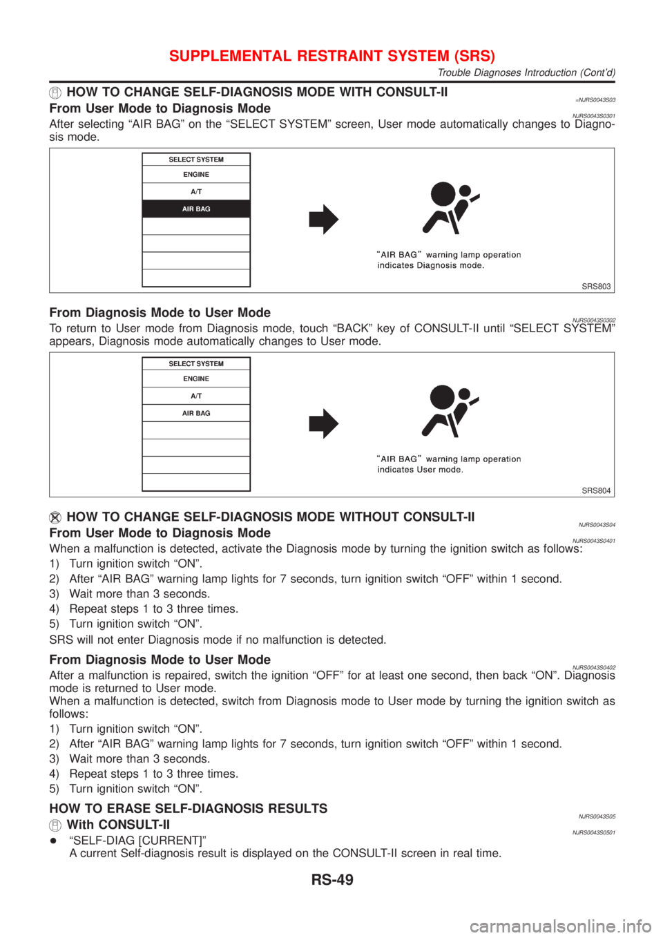
HOW TO CHANGE SELF-DIAGNOSIS MODE WITH CONSULT-II=NJRS0043S03From User Mode to Diagnosis ModeNJRS0043S0301After selecting ªAIR BAGº on the ªSELECT SYSTEMº screen, User mode automatically changes to Diagno-
sis mode.
SRS803
From Diagnosis Mode to User ModeNJRS0043S0302To return to User mode from Diagnosis mode, touch ªBACKº key of CONSULT-II until ªSELECT SYSTEMº
appears, Diagnosis mode automatically changes to User mode.
SRS804
HOW TO CHANGE SELF-DIAGNOSIS MODE WITHOUT CONSULT-IINJRS0043S04From User Mode to Diagnosis ModeNJRS0043S0401When a malfunction is detected, activate the Diagnosis mode by turning the ignition switch as follows:
1) Turn ignition switch ªONº.
2) After ªAIR BAGº warning lamp lights for 7 seconds, turn ignition switch ªOFFº within 1 second.
3) Wait more than 3 seconds.
4) Repeat steps 1 to 3 three times.
5) Turn ignition switch ªONº.
SRS will not enter Diagnosis mode if no malfunction is detected.
From Diagnosis Mode to User ModeNJRS0043S0402After a malfunction is repaired, switch the ignition ªOFFº for at least one second, then back ªONº. Diagnosis
mode is returned to User mode.
When a malfunction is detected, switch from Diagnosis mode to User mode by turning the ignition switch as
follows:
1) Turn ignition switch ªONº.
2) After ªAIR BAGº warning lamp lights for 7 seconds, turn ignition switch ªOFFº within 1 second.
3) Wait more than 3 seconds.
4) Repeat steps 1 to 3 three times.
5) Turn ignition switch ªONº.
HOW TO ERASE SELF-DIAGNOSIS RESULTSNJRS0043S05With CONSULT-IINJRS0043S0501+ªSELF-DIAG [CURRENT]º
A current Self-diagnosis result is displayed on the CONSULT-II screen in real time.
SUPPLEMENTAL RESTRAINT SYSTEM (SRS)
Trouble Diagnoses Introduction (Cont'd)
RS-49
Page 2758 of 2898
After the malfunction is repaired completely, no malfunction is detected on ªSELF-DIAG [CURRENT]º.
+ªSELF-DIAG [PAST]º
Return to the ªSELF-DIAG [CURRENT]º CONSULT-II screen by pushing ªBACKº key of CONSULT-II and
select ªSELF-DIAG [CURRENT]º in SELECT DIAG MODE. Touch ªERASEº in ªSELF-DIAG [CURRENT]º
mode.
NOTE:
If the memory of the malfunction in ªSELF-DIAG [PAST]º is not erased, the User mode shows the sys-
tem malfunction by the operation of the warning lamp even if the malfunction is repaired completely.
SRS701
+ªTROUBLE DIAG RECORDº
The memory of ªTROUBLE DIAG RECORDº cannot be erased.
Without CONSULT-IINJRS0043S0502After a malfunction is repaired, switch the ignition ªOFFº for at least one second, then back ªONº. Diagnosis
mode returns to the User mode. At that time, the self-diagnostic result is cleared.
SUPPLEMENTAL RESTRAINT SYSTEM (SRS)
Trouble Diagnoses Introduction (Cont'd)
RS-50
Page 2769 of 2898
![NISSAN ALMERA 2001 Service Manual SRS772
7. Diagnostic codes are displayed on ªSELF-DIAG [CURRENT]º.
SRS701
4-door Sedan
If no malfunction is detected on ªSELF-DIAG [CURRENT]º even
though malfunction is detected in ªSRS Operation NISSAN ALMERA 2001 Service Manual SRS772
7. Diagnostic codes are displayed on ªSELF-DIAG [CURRENT]º.
SRS701
4-door Sedan
If no malfunction is detected on ªSELF-DIAG [CURRENT]º even
though malfunction is detected in ªSRS Operation](/manual-img/5/57348/w960_57348-2768.png)
SRS772
7. Diagnostic codes are displayed on ªSELF-DIAG [CURRENT]º.
SRS701
4-door Sedan
If no malfunction is detected on ªSELF-DIAG [CURRENT]º even
though malfunction is detected in ªSRS Operation Checkº, check
the battery voltage.
If the battery voltage is less than 9V, charge the battery. Then go
to DIAGNOSTIC PROCEDURE 3, page RS-66.
If the battery voltage is OK, go to DIAGNOSTIC PROCEDURE 4,
page RS-68, to diagnose the following cases:
+Self-diagnostic result ªSELF-DIAG [PAST]º (previously stored
in the memory) might not be erased after repair.
+The SRS system malfunctions intermittently.
Hatchback
If no malfunction is detected on ªSELF-DIAG [CURRENT]º but mal-
function is indicated by the ªAIR BAGº warning lamp, go to DIAG-
NOSTIC PROCEDURE 4, page RS-68, to diagnose the following
situations:
+Self-diagnostic result ªSELF-DIAG [PAST]º (previously stored
in the memory) might not be erased after repair.
+The SRS system malfunctions intermittently.
8. Touch ªPRINTº.
9. Compare diagnostic codes to ªCONSULT-II Diagnostic Code
Chartº, page RS-62 (4-door Sedan) or RS-64 (Hatchback).
10. Touch ªBACKº key of CONSULT-II until ªSELECT SYSTEMº
appears in order to return to User mode from Diagnosis mode.
11. Turn ignition switch ªOFFº, then turn off and disconnect
CONSULT-II, and disconnect both battery cables.
12. Repair the system as outlined by the ªRepair orderº in ªCON-
SULT-II Diagnostic Code Chartº, that corresponds to the self-
diagnostic result. For replacement procedure of component
parts, refer to RS-26.
13. After repairing the system, go to DIAGNOSTIC PROCEDURE
3, page RS-66 for final checking.
SUPPLEMENTAL RESTRAINT SYSTEM (SRS)
Trouble Diagnoses with CONSULT-II (Cont'd)
RS-61
Page 2775 of 2898
SRS771
5. Touch ªAIR BAGº.
SRS697
6. Touch ªSELF-DIAG [CURRENT]º.
SRS701
7. If no malfunction is detected on ªSELF-DIAG [CURRENT]º,
repair of SRS is completed. Go to step 8.
If any malfunction is displayed on ªSELF-DIAG [CURRENT]º,
the malfunctioning part is not repaired completely or another
malfunctioning part is detected. Go to DIAGNOSTIC PROCE-
DURE 2, page RS-60, and repair malfunctioning part com-
pletely.
SRS773
8. Touch ªERASEº.
NOTE:
Touch ªERASEº to clear the memory of the malfunction
(ªSELF-DIAG [PAST]º).
If the memory of the malfunction in ªSELF-DIAG [PAST]º is not
erased, the User mode shows the system malfunction by the
operation of the warning lamp even if the malfunction is repaired
completely.
SRS697
9. Touch ªBACKº key of CONSULT-II to ªSELECT SYSTEMº
screen. Touch ªSELF-DIAG [PAST]º.
SUPPLEMENTAL RESTRAINT SYSTEM (SRS)
Trouble Diagnoses with CONSULT-II (Cont'd)
RS-67
Page 2776 of 2898
![NISSAN ALMERA 2001 Service Manual SRS702
10. Check that no malfunction is detected on ªSELF-DIAG
[PAST]º.
11. Touch ªBACKº key of CONSULT-II until ªSELECT SYSTEMº
appears in order to return to User mode from Diagnosis mode.
12. NISSAN ALMERA 2001 Service Manual SRS702
10. Check that no malfunction is detected on ªSELF-DIAG
[PAST]º.
11. Touch ªBACKº key of CONSULT-II until ªSELECT SYSTEMº
appears in order to return to User mode from Diagnosis mode.
12.](/manual-img/5/57348/w960_57348-2775.png)
SRS702
10. Check that no malfunction is detected on ªSELF-DIAG
[PAST]º.
11. Touch ªBACKº key of CONSULT-II until ªSELECT SYSTEMº
appears in order to return to User mode from Diagnosis mode.
12. Turn ignition switch ªOFFº, then turn off and disconnect CON-
SULT-II.
13. Go to ªSRS Operation Checkº, page RS-59 to check SRS
operation by using ªAIR BAGº warning lamp with User mode.
DIAGNOSTIC PROCEDURE 4 (CONTINUED FROM
DIAGNOSTIC PROCEDURE 2)
NJRS0048S03Inspecting SRS malfunctioning record
1 CONSIDER POSSIBILITY OF NOT ERASING SELF-DIAGNOSTIC RESULT AFTER REPAIRING
Is it the first time for maintenance of SRS?
YesorNo
Ye s©Go to DIAGNOSTIC PROCEDURE 5 (RS-68).
No©Self-diagnostic result ªSELF-DIAG [PAST]º (previously stored in the memory) might not
be erased after repair. Go to DIAGNOSTIC PROCEDURE 3, step 8 (RS-66).
SRS834-A
SRS872
DIAGNOSTIC PROCEDURE 5NJRS0048S04Inspecting SRS intermittent malfunction by using CONSULT-II
Ð Diagnosis mode
1. Turn ignition switch ªOFFº.
2. Connect CONSULT-II to data link connector.
SUPPLEMENTAL RESTRAINT SYSTEM (SRS)
Trouble Diagnoses with CONSULT-II (Cont'd)
RS-68
Page 2778 of 2898

SRS697
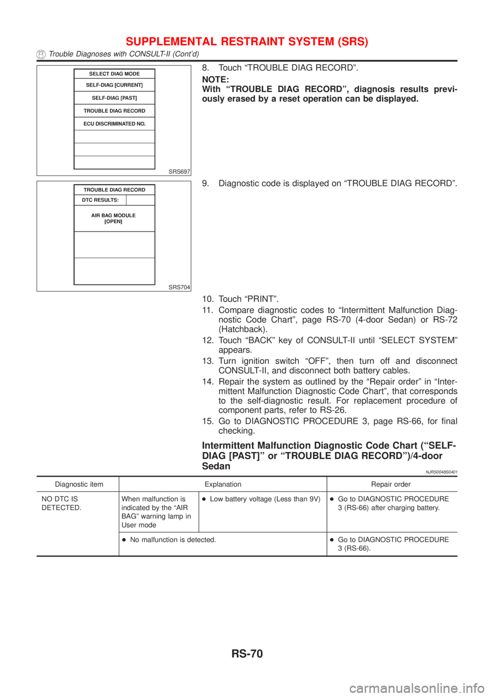
8. Touch ªTROUBLE DIAG RECORDº.
NOTE:
With ªTROUBLE DIAG RECORDº, diagnosis results previ-
ously erased by a reset operation can be displayed.
SRS704
9. Diagnostic code is displayed on ªTROUBLE DIAG RECORDº.
10. Touch ªPRINTº.
11. Compare diagnostic codes to ªIntermittent Malfunction Diag-
nostic Code Chartº, page RS-70 (4-door Sedan) or RS-72
(Hatchback).
12. Touch ªBACKº key of CONSULT-II until ªSELECT SYSTEMº
appears.
13. Turn ignition switch ªOFFº, then turn off and disconnect
CONSULT-II, and disconnect both battery cables.
14. Repair the system as outlined by the ªRepair orderº in ªInter-
mittent Malfunction Diagnostic Code Chartº, that corresponds
to the self-diagnostic result. For replacement procedure of
component parts, refer to RS-26.
15. Go to DIAGNOSTIC PROCEDURE 3, page RS-66, for final
checking.
Intermittent Malfunction Diagnostic Code Chart (ªSELF-
DIAG [PAST]º or ªTROUBLE DIAG RECORDº)/4-door
Sedan
NJRS0048S0401
Diagnostic item Explanation Repair order
NO DTC IS
DETECTED.When malfunction is
indicated by the ªAIR
BAGº warning lamp in
User mode+Low battery voltage (Less than 9V)+Go to DIAGNOSTIC PROCEDURE
3 (RS-66) after charging battery.
+No malfunction is detected.+Go to DIAGNOSTIC PROCEDURE
3 (RS-66).
SUPPLEMENTAL RESTRAINT SYSTEM (SRS)
Trouble Diagnoses with CONSULT-II (Cont'd)
RS-70
Page 2842 of 2898

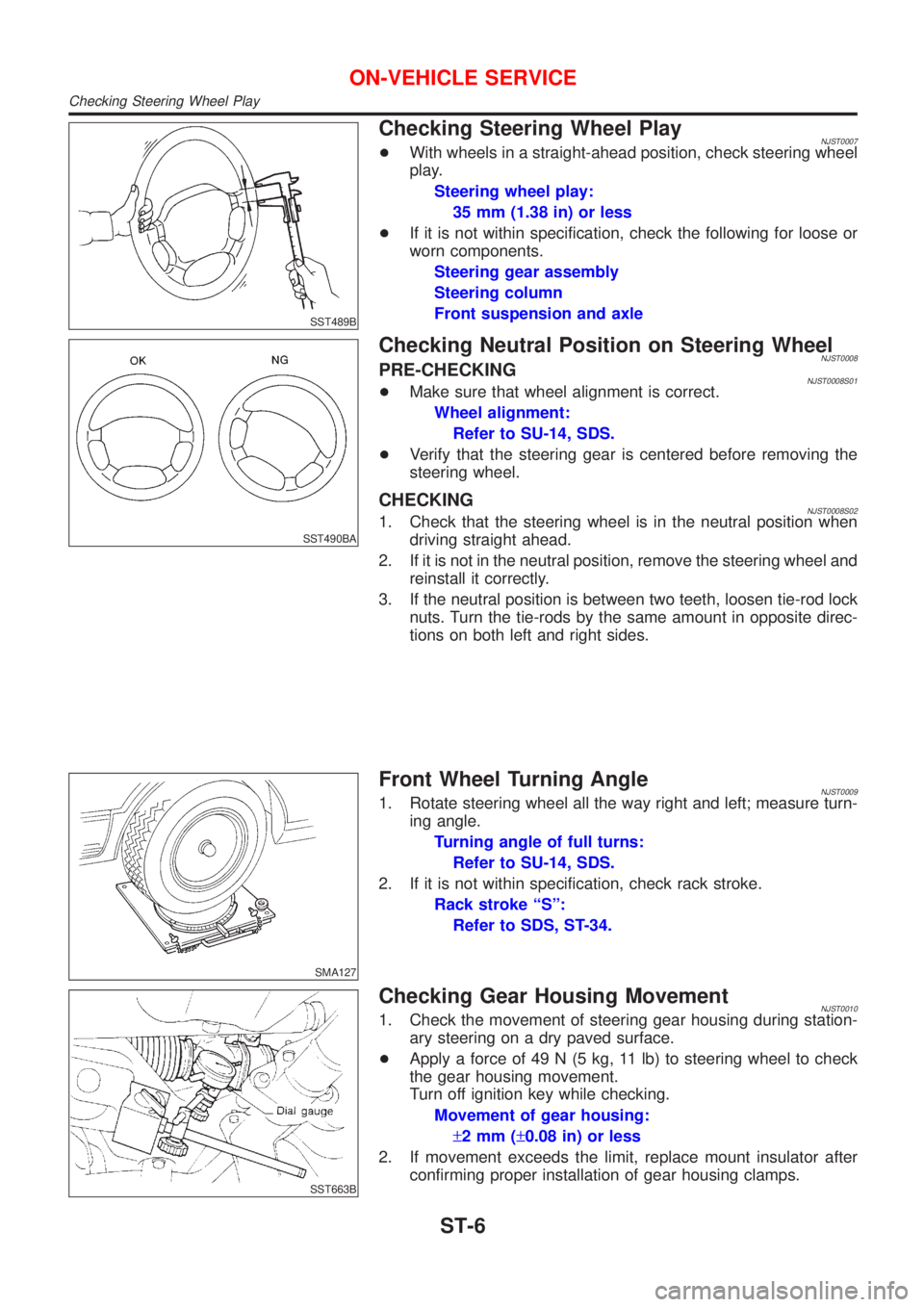
SST489B
Checking Steering Wheel PlayNJST0007+With wheels in a straight-ahead position, check steering wheel
play.
Steering wheel play:
35 mm (1.38 in) or less
+If it is not within specification, check the following for loose or
worn components.
Steering gear assembly
Steering column
Front suspension and axle
SST490BA
Checking Neutral Position on Steering WheelNJST0008PRE-CHECKINGNJST0008S01+Make sure that wheel alignment is correct.
Wheel alignment:
Refer to SU-14, SDS.
+Verify that the steering gear is centered before removing the
steering wheel.
CHECKINGNJST0008S021. Check that the steering wheel is in the neutral position when
driving straight ahead.
2. If it is not in the neutral position, remove the steering wheel and
reinstall it correctly.
3. If the neutral position is between two teeth, loosen tie-rod lock
nuts. Turn the tie-rods by the same amount in opposite direc-
tions on both left and right sides.
SMA127
Front Wheel Turning AngleNJST00091. Rotate steering wheel all the way right and left; measure turn-
ing angle.
Turning angle of full turns:
Refer to SU-14, SDS.
2. If it is not within specification, check rack stroke.
Rack stroke ªSº:
Refer to SDS, ST-34.
SST663B
Checking Gear Housing MovementNJST00101. Check the movement of steering gear housing during station-
ary steering on a dry paved surface.
+Apply a force of 49 N (5 kg, 11 lb) to steering wheel to check
the gear housing movement.
Turn off ignition key while checking.
Movement of gear housing:
±2mm(±0.08 in) or less
2. If movement exceeds the limit, replace mount insulator after
confirming proper installation of gear housing clamps.
ON-VEHICLE SERVICE
Checking Steering Wheel Play
ST-6
Page 2848 of 2898

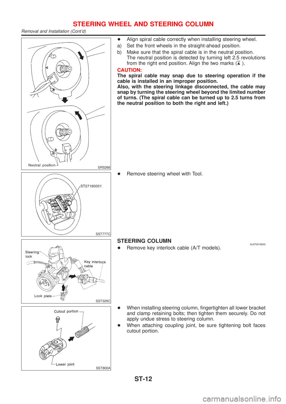
SRS266
+Align spiral cable correctly when installing steering wheel.
a) Set the front wheels in the straight-ahead position.
b) Make sure that the spiral cable is in the neutral position.
The neutral position is detected by turning left 2.5 revolutions
from the right end position. Align the two marks (
).
CAUTION:
The spiral cable may snap due to steering operation if the
cable is installed in an improper position.
Also, with the steering linkage disconnected, the cable may
snap by turning the steering wheel beyond the limited number
of turns. (The spiral cable can be turned up to 2.5 turns from
the neutral position to both the right and left.)
SST777C
+Remove steering wheel with Tool.
SST329C
STEERING COLUMNNJST0018S02+Remove key interlock cable (A/T models).
SST800A
+When installing steering column, fingertighten all lower bracket
and clamp retaining bolts; then tighten them securely. Do not
apply undue stress to steering column.
+When attaching coupling joint, be sure tightening bolt faces
cutout portion.
STEERING WHEEL AND STEERING COLUMN
Removal and Installation (Cont'd)
ST-12