Page 2149 of 2898

NJEM0007
1. Warm up engine.
2. Turn ignition switch OFF.
3. Release fuel pressure.
Refer to EC-40, ªReleasing Fuel Pressureº.
4. Remove ignition coils.
5. Remove spark plugs.
+Clean area around plug with compressed air before removing
the spark plug.
SEM973E
AEM308
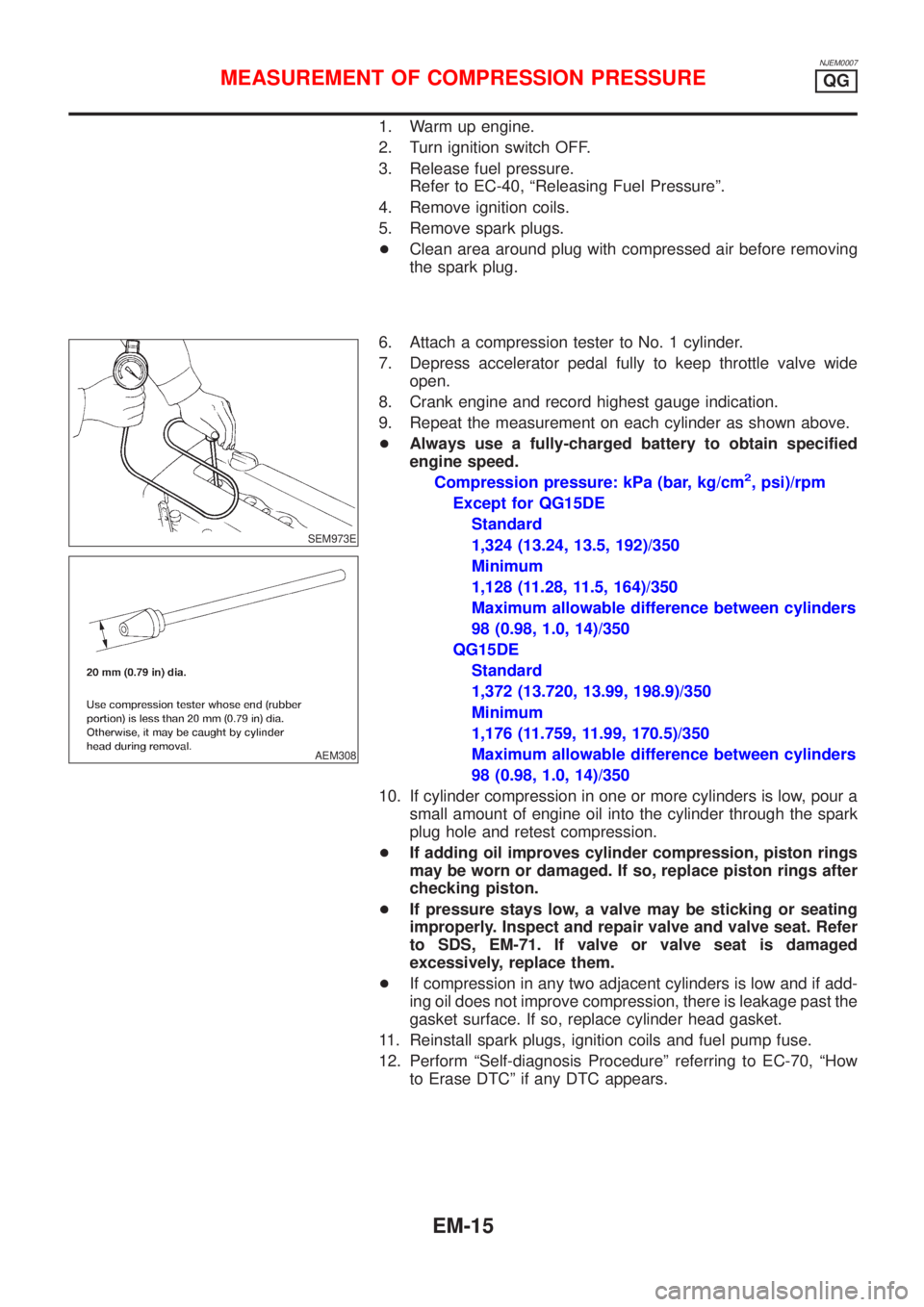
6. Attach a compression tester to No. 1 cylinder.
7. Depress accelerator pedal fully to keep throttle valve wide
open.
8. Crank engine and record highest gauge indication.
9. Repeat the measurement on each cylinder as shown above.
+Always use a fully-charged battery to obtain specified
engine speed.
Compression pressure: kPa (bar, kg/cm
2, psi)/rpm
Except for QG15DE
Standard
1,324 (13.24, 13.5, 192)/350
Minimum
1,128 (11.28, 11.5, 164)/350
Maximum allowable difference between cylinders
98 (0.98, 1.0, 14)/350
QG15DE
Standard
1,372 (13.720, 13.99, 198.9)/350
Minimum
1,176 (11.759, 11.99, 170.5)/350
Maximum allowable difference between cylinders
98 (0.98, 1.0, 14)/350
10. If cylinder compression in one or more cylinders is low, pour a
small amount of engine oil into the cylinder through the spark
plug hole and retest compression.
+If adding oil improves cylinder compression, piston rings
may be worn or damaged. If so, replace piston rings after
checking piston.
+If pressure stays low, a valve may be sticking or seating
improperly. Inspect and repair valve and valve seat. Refer
to SDS, EM-71. If valve or valve seat is damaged
excessively, replace them.
+If compression in any two adjacent cylinders is low and if add-
ing oil does not improve compression, there is leakage past the
gasket surface. If so, replace cylinder head gasket.
11. Reinstall spark plugs, ignition coils and fuel pump fuse.
12. Perform ªSelf-diagnosis Procedureº referring to EC-70, ªHow
to Erase DTCº if any DTC appears.
MEASUREMENT OF COMPRESSION PRESSUREQG
EM-15
Page 2150 of 2898
CheckingNJEM0042
SEM100G
1. Inspect for cracks, fraying, wear or oil adhesion. If necessary,
replace with a new one.
+When replacing belt, make sure the new belt has the same
number of ribs as the old one.
2. Inspect drive belt deflections by pushing on the belt midway
between pulleys.
3. Turn crankshaft two revolutions and recheck drive belt deflec-
tion.
+Inspect drive belt deflection when engine is cold.
+Adjust if belt deflections exceed the limit.
DRIVE BELTSQG
Checking
EM-16
Page 2151 of 2898
Belt deflection:
Unit: mm (in)
Applied engineUsed belt deflection
Deflection
of new belt
LimitDeflection
after
adjustment
AlternatorWith air
conditioner
compressorQG15´18DE 8.1 (0.319)5.3 - 5.7
(0.209 -
0.224)4.5 - 5.0
(0.177 -
0.197)
Without air
conditioner
compressorQG15´18DE10.2
(0.402)6.5 - 7.0
(0.256 -
0.276)5.5 - 6.1
(0.217 -
0.240)
Power steering oil
pumpSedan with
QG15DE8.5 (0.335)5.2 - 5.8
(0.205 -
0.228)4.6 - 5.2
(0.181 -
0.205)
Except for
Sedan with
QG15DE7.1 (0.280)4.4 - 4.9
(0.173 -
0.193)3.9 - 4.4
(0.154 -
0.173)
Applied pushing force 98 N (10 kg, 22 lb)
Inspect drive belt deflections when engine is cold.
DRIVE BELTSQG
Checking (Cont'd)
EM-17
Page 2154 of 2898
ComponentsNJEM0008
SEM391G
SEM067F
RemovalNJEM00091. Remove front RH side cover.
2. Drain engine oil.
3. Remove front exhaust tube.
Refer to FE-15, ªEXHAUST SYSTEMº.
4. Set a suitable transmission jack under transaxle and lift engine
with engine slinger.
5. Remove center member.
OIL PANQG
Components
EM-20
Page 2155 of 2898
SEM071FA
SEM110G
6. Remove engine gussets.
Refer to MT-24 or AT-355, ªInstallationº.
7. Remove rear plate cover (A/T models).
SEM365EB
8. Remove oil pan.
a. Insert Tool between cylinder block and oil pan.
1)Be careful not to damage aluminum mating face.
Do not insert screwdriver, or oil pan flange will be dam-
aged.
b. Slide Tool by tapping on the side of the Tool with a hammer.
SEM295C
InstallationNJEM00101. Use a scraper to remove old liquid gasket from mating surface
of oil pan.
+Also remove old liquid gasket from mating surface of cyl-
inder block.
SEM015E
2. Apply a continuous bead of liquid gasket to mating surface of
oil pan.
+Use Genuine Liquid Gasket or equivalent.
+Apply to groove on mating surface.
+Allow 7 mm (0.28 in) clearance around bolt holes.
OIL PANQG
Removal (Cont'd)
EM-21
Page 2156 of 2898
SEM259G
+Be sure liquid gasket diameter is 3.5 to 4.5 mm (0.138 to
0.177 in).
+Attaching should be done within 5 minutes after coating.
SEM072F
3. Install oil pan.
+Tighten oil pan nuts and bolts in the numerical order.
+Wait at least 30 minutes before refilling engine oil.
4. Install parts in reverse order of removal.
OIL PANQG
Installation (Cont'd)
EM-22
Page 2158 of 2898

CAUTION:
+After removing timing chain, do not turn crankshaft and
camshaft separately, or valves will strike piston heads.
+When installing chain tensioner, oil seats, or other sliding
parts, lubricate contacting surfaces with new engine oil.
+Apply new engine oil to bolt threads and seat surfaces
when installing camshaft sprocket and crankshaft pulley.
+When removing oil pump assembly, remove camshaft
position sensor (PHASE), then remove timing chain from
engine.
+Be careful not to damage sensor edges.
SEM869F
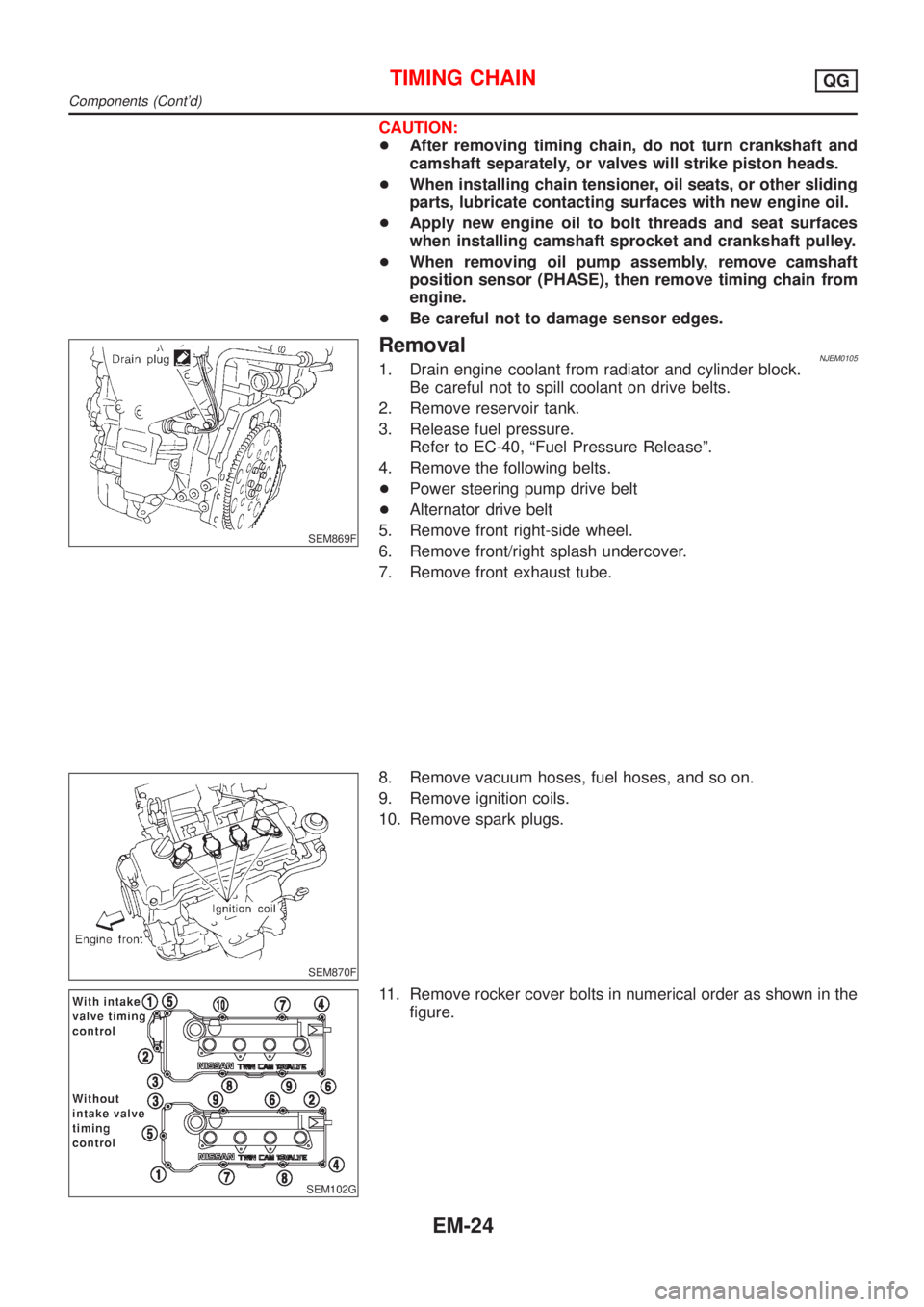
RemovalNJEM01051. Drain engine coolant from radiator and cylinder block.
Be careful not to spill coolant on drive belts.
2. Remove reservoir tank.
3. Release fuel pressure.
Refer to EC-40, ªFuel Pressure Releaseº.
4. Remove the following belts.
+Power steering pump drive belt
+Alternator drive belt
5. Remove front right-side wheel.
6. Remove front/right splash undercover.
7. Remove front exhaust tube.
SEM870F
8. Remove vacuum hoses, fuel hoses, and so on.
9. Remove ignition coils.
10. Remove spark plugs.
SEM102G
11. Remove rocker cover bolts in numerical order as shown in the
figure.
TIMING CHAINQG
Components (Cont'd)
EM-24
Page 2160 of 2898
SEM008G
20. Remove cylinder head bolts at engine front side.
SEM879F
21. Remove oil pan. Refer to EM-20, ªRemovalº.
22. Remove oil strainer.
SEM880F
23. Remove starter motor, and set ring gear stopper using mount-
ing bolt holes.
SEM881F
24. Loosen crankshaft pulley bolt.
25. Remove crankshaft pulley with a suitable puller.
SEM103G
26. Remove RH engine mounting.
TIMING CHAINQG
Removal (Cont'd)
EM-26