Page 2217 of 2898
NJEM0053
JEM111G
1. Warm up engine.
2. Turn ignition switch OFF.
3. Using CONSULT-II, make sure no error codes are indicated for
self-diagnosis items. Refer to EC-10, ªTrouble Diagnosis Ð
INDEXº.
+Do not disconnect CONSULT-II until the end of this operation;
it will be used to check engine rpm and for error detection at
the end of this operation.
4. Disconnect the negative battery terminal.
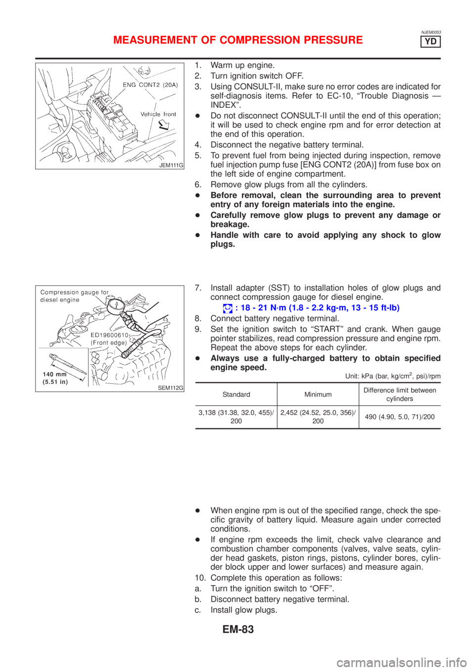
5. To prevent fuel from being injected during inspection, remove
fuel injection pump fuse [ENG CONT2 (20A)] from fuse box on
the left side of engine compartment.
6. Remove glow plugs from all the cylinders.
+Before removal, clean the surrounding area to prevent
entry of any foreign materials into the engine.
+Carefully remove glow plugs to prevent any damage or
breakage.
+Handle with care to avoid applying any shock to glow
plugs.
SEM112G
7. Install adapter (SST) to installation holes of glow plugs and
connect compression gauge for diesel engine.
: 18 - 21 N´m (1.8 - 2.2 kg-m, 13 - 15 ft-lb)
8. Connect battery negative terminal.
9. Set the ignition switch to ªSTARTº and crank. When gauge
pointer stabilizes, read compression pressure and engine rpm.
Repeat the above steps for each cylinder.
+Always use a fully-charged battery to obtain specified
engine speed.
Unit: kPa (bar, kg/cm2, psi)/rpm
Standard MinimumDifference limit between
cylinders
3,138 (31.38, 32.0, 455)/
2002,452 (24.52, 25.0, 356)/
200490 (4.90, 5.0, 71)/200
+When engine rpm is out of the specified range, check the spe-
cific gravity of battery liquid. Measure again under corrected
conditions.
+If engine rpm exceeds the limit, check valve clearance and
combustion chamber components (valves, valve seats, cylin-
der head gaskets, piston rings, pistons, cylinder bores, cylin-
der block upper and lower surfaces) and measure again.
10. Complete this operation as follows:
a. Turn the ignition switch to ªOFFº.
b. Disconnect battery negative terminal.
c. Install glow plugs.
MEASUREMENT OF COMPRESSION PRESSUREYD
EM-83
Page 2219 of 2898
JEM249G
InspectionNJEM0088+Before inspecting the engine, make sure the engine has
cooled down; wait approximately 30 minutes after the engine
has been stopped.
+Visually inspect all belts for wear, damage, or cracks on con-
tacting surfaces and edge areas.
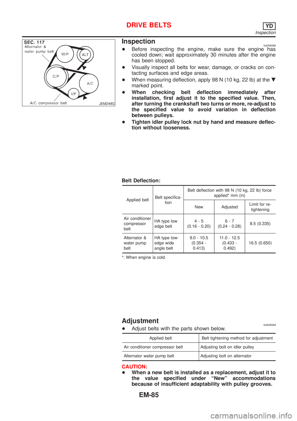
+When measuring deflection, apply 98 N (10 kg, 22 lb) at the.
marked point.
+When checking belt deflection immediately after
installation, first adjust it to the specified value. Then,
after turning the crankshaft two turns or more, re-adjust to
the specified value to avoid variation in deflection
between pulleys.
+Tighten idler pulley lock nut by hand and measure deflec-
tion without looseness.
Belt Deflection:
Applied beltBelt specifica-
tionBelt deflection with 98 N (10 kg, 22 lb) force
applied* mm (in)
New AdjustedLimit for re-
tightening
Air conditioner
compressor
beltHA type low
edge belt4-5
(0.16 - 0.20)6-7
(0.24 - 0.28)8.5 (0.335)
Alternator &
water pump
beltHA type low-
edge wide
angle belt9.0 - 10.5
(0.354 -
0.413)11.0 - 12.5
(0.433 -
0.492)16.5 (0.650)
*: When engine is cold.
AdjustmentNJEM0089+Adjust belts with the parts shown below.
Applied belt Belt tightening method for adjustment
Air conditioner compressor belt Adjusting bolt on idler pulley
Alternator water pump belt Adjusting bolt on alternator
CAUTION:
+When a new belt is installed as a replacement, adjust it to
the value specified under ªNewº accommodations
because of insufficient adaptability with pulley grooves.
DRIVE BELTSYD
Inspection
EM-85
Page 2223 of 2898
ComponentsNJEM0054
SEM654G
RemovalNJEM0055CAUTION:
When removing the upper oil pan from engine, first remove
the crankshaft position sensor (TDC sensor) from the assem-
bly.
Be careful not to damage sensor edges and signal plate teeth.
1. Remove right engine undercover.
2. Drain engine oil.
OIL PANYD
Components
EM-89
Page 2224 of 2898
JEM114G
3. Remove air compressor bracket.
4. Remove lower oil pan bolts.
+Loosen bolts in the reverse order of that shown in the figure.
SEM544G
5. Remove lower oil pan.
a. Insert Tool between upper oil pan and lower oil pan.
+Be careful not to damage aluminum mating surface.
+Do not insert screwdriver, or oil pan flange will be
deformed.
SEM545G
b. Slide Tool by tapping on the side of the Tool with a hammer.
c. Remove lower oil pan.
6. Remove oil strainer.
7. Remove front exhaust tube and its support.
Refer to FE-32, ªRemoval and Installationº.
JEM553G
8. Set a suitable transmission jack under transaxle and hoist
engine with engine slinger.
+Place the jack as close to the center as possible for support.
9. Remove front and rear engine mounting nuts and bolts.
10. Remove center member.
11. Remove crankshaft position sensor (TDC sensor) from oil pan.
12. Remove oil pan cover.
OIL PANYD
Removal (Cont'd)
EM-90
Page 2225 of 2898
JEM116G
13. For Europe only, remove catalyst rear diffuser, EM-110, ªCata-
lystº.
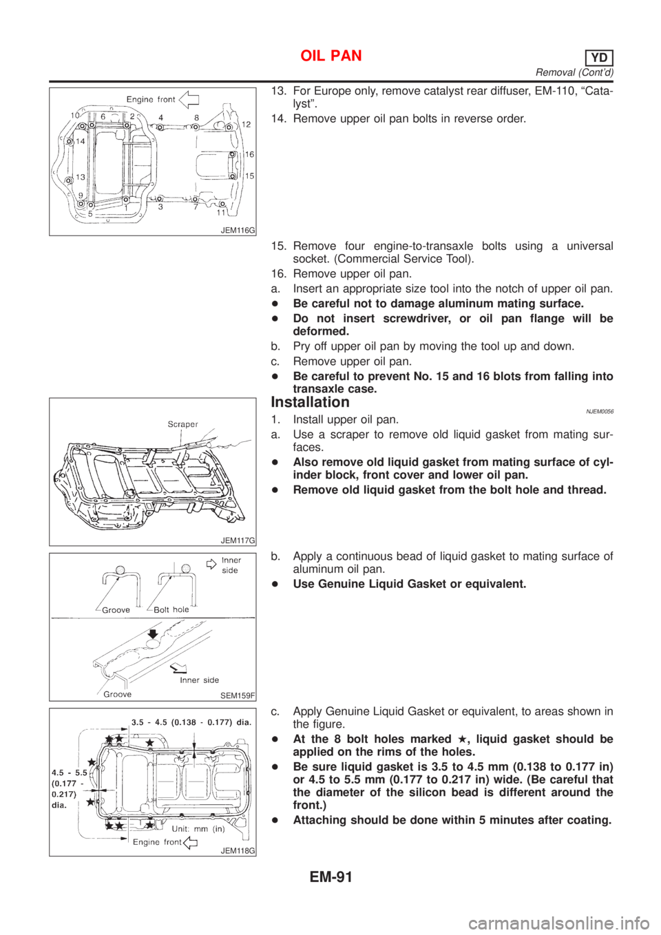
14. Remove upper oil pan bolts in reverse order.
15. Remove four engine-to-transaxle bolts using a universal
socket. (Commercial Service Tool).
16. Remove upper oil pan.
a. Insert an appropriate size tool into the notch of upper oil pan.
+Be careful not to damage aluminum mating surface.
+Do not insert screwdriver, or oil pan flange will be
deformed.
b. Pry off upper oil pan by moving the tool up and down.
c. Remove upper oil pan.
+Be careful to prevent No. 15 and 16 blots from falling into
transaxle case.
JEM117G
InstallationNJEM00561. Install upper oil pan.
a. Use a scraper to remove old liquid gasket from mating sur-
faces.
+Also remove old liquid gasket from mating surface of cyl-
inder block, front cover and lower oil pan.
+Remove old liquid gasket from the bolt hole and thread.
SEM159F
b. Apply a continuous bead of liquid gasket to mating surface of
aluminum oil pan.
+Use Genuine Liquid Gasket or equivalent.
JEM118G
c. Apply Genuine Liquid Gasket or equivalent, to areas shown in
the figure.
+At the 8 bolt holes markedH, liquid gasket should be
applied on the rims of the holes.
+Be sure liquid gasket is 3.5 to 4.5 mm (0.138 to 0.177 in)
or 4.5 to 5.5 mm (0.177 to 0.217 in) wide. (Be careful that
the diameter of the silicon bead is different around the
front.)
+Attaching should be done within 5 minutes after coating.
OIL PANYD
Removal (Cont'd)
EM-91
Page 2226 of 2898
JEM116G
d. Install upper oil pan.
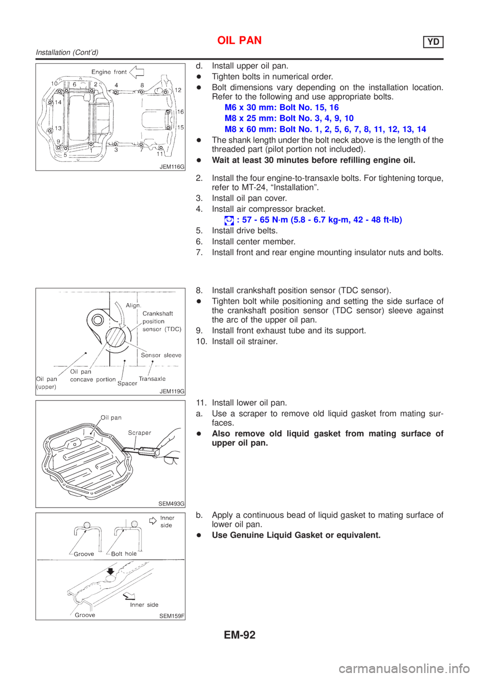
+Tighten bolts in numerical order.
+Bolt dimensions vary depending on the installation location.
Refer to the following and use appropriate bolts.
M6 x 30 mm: Bolt No. 15, 16
M8 x 25 mm: Bolt No. 3, 4, 9, 10
M8 x 60 mm: Bolt No. 1, 2, 5, 6, 7, 8, 11, 12, 13, 14
+The shank length under the bolt neck above is the length of the
threaded part (pilot portion not included).
+Wait at least 30 minutes before refilling engine oil.
2. Install the four engine-to-transaxle bolts. For tightening torque,
refer to MT-24, ªInstallationº.
3. Install oil pan cover.
4. Install air compressor bracket.
: 57 - 65 N´m (5.8 - 6.7 kg-m, 42 - 48 ft-lb)
5. Install drive belts.
6. Install center member.
7. Install front and rear engine mounting insulator nuts and bolts.
JEM119G
8. Install crankshaft position sensor (TDC sensor).
+Tighten bolt while positioning and setting the side surface of
the crankshaft position sensor (TDC sensor) sleeve against
the arc of the upper oil pan.
9. Install front exhaust tube and its support.
10. Install oil strainer.
SEM493G
11. Install lower oil pan.
a. Use a scraper to remove old liquid gasket from mating sur-
faces.
+Also remove old liquid gasket from mating surface of
upper oil pan.
SEM159F
b. Apply a continuous bead of liquid gasket to mating surface of
lower oil pan.
+Use Genuine Liquid Gasket or equivalent.
OIL PANYD
Installation (Cont'd)
EM-92
Page 2227 of 2898
SEM494G
+Be sure liquid gasket is 3.5 to 4.5 mm (0.138 to 0.177 in)
wide.
+Attaching should be done within 5 minutes after coating.
JEM114G
c. Install lower oil pan.
+Tighten in numerical order shown in the figure.
+Wait at least 30 minutes before refilling engine oil.
OIL PANYD
Installation (Cont'd)
EM-93
Page 2228 of 2898
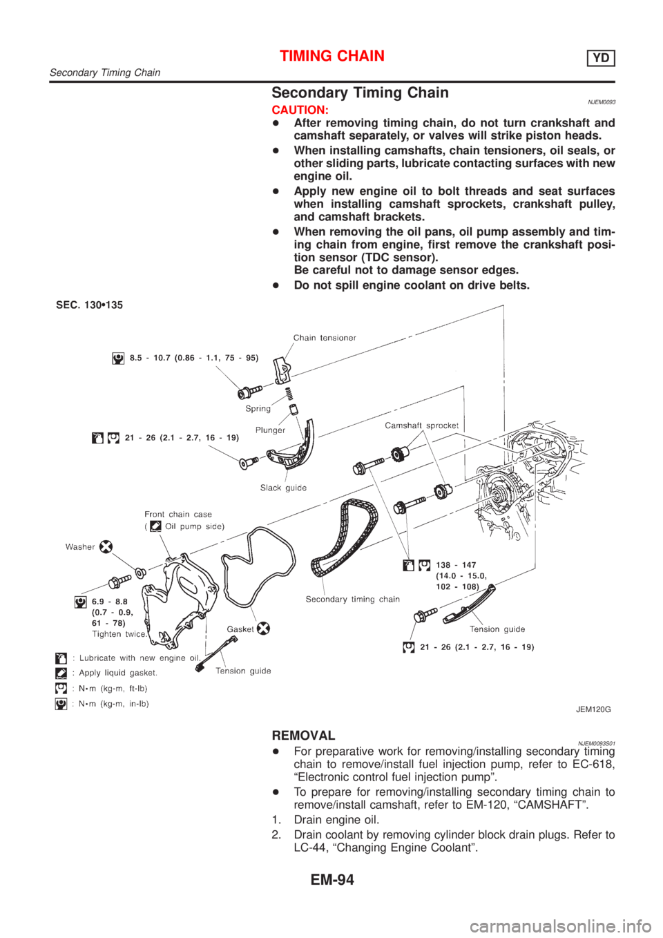
Secondary Timing ChainNJEM0093CAUTION:
+After removing timing chain, do not turn crankshaft and
camshaft separately, or valves will strike piston heads.
+When installing camshafts, chain tensioners, oil seals, or
other sliding parts, lubricate contacting surfaces with new
engine oil.
+Apply new engine oil to bolt threads and seat surfaces
when installing camshaft sprockets, crankshaft pulley,
and camshaft brackets.
+When removing the oil pans, oil pump assembly and tim-
ing chain from engine, first remove the crankshaft posi-
tion sensor (TDC sensor).
Be careful not to damage sensor edges.
+Do not spill engine coolant on drive belts.
JEM120G
REMOVALNJEM0093S01+For preparative work for removing/installing secondary timing
chain to remove/install fuel injection pump, refer to EC-618,
ªElectronic control fuel injection pumpº.
+To prepare for removing/installing secondary timing chain to
remove/install camshaft, refer to EM-120, ªCAMSHAFTº.
1. Drain engine oil.
2. Drain coolant by removing cylinder block drain plugs. Refer to
LC-44, ªChanging Engine Coolantº.
TIMING CHAINYD
Secondary Timing Chain
EM-94