Page 2290 of 2898
JEM213G
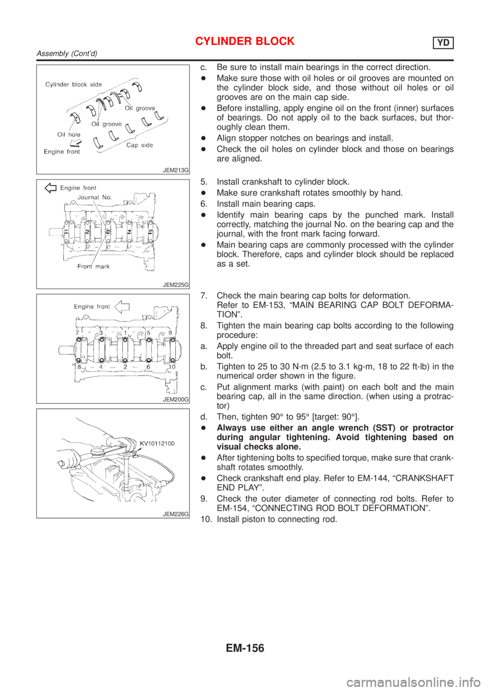
c. Be sure to install main bearings in the correct direction.
+Make sure those with oil holes or oil grooves are mounted on
the cylinder block side, and those without oil holes or oil
grooves are on the main cap side.
+Before installing, apply engine oil on the front (inner) surfaces
of bearings. Do not apply oil to the back surfaces, but thor-
oughly clean them.
+Align stopper notches on bearings and install.
+Check the oil holes on cylinder block and those on bearings
are aligned.
JEM225G
5. Install crankshaft to cylinder block.
+Make sure crankshaft rotates smoothly by hand.
6. Install main bearing caps.
+Identify main bearing caps by the punched mark. Install
correctly, matching the journal No. on the bearing cap and the
journal, with the front mark facing forward.
+Main bearing caps are commonly processed with the cylinder
block. Therefore, caps and cylinder block should be replaced
as a set.
JEM200G
JEM226G
7. Check the main bearing cap bolts for deformation.
Refer to EM-153, ªMAIN BEARING CAP BOLT DEFORMA-
TIONº.
8. Tighten the main bearing cap bolts according to the following
procedure:
a. Apply engine oil to the threaded part and seat surface of each
bolt.
b. Tighten to 25 to 30 N´m (2.5 to 3.1 kg-m, 18 to 22 ft-lb) in the
numerical order shown in the figure.
c. Put alignment marks (with paint) on each bolt and the main
bearing cap, all in the same direction. (when using a protrac-
tor)
d. Then, tighten 90É to 95É [target: 90É].
+Always use either an angle wrench (SST) or protractor
during angular tightening. Avoid tightening based on
visual checks alone.
+After tightening bolts to specified torque, make sure that crank-
shaft rotates smoothly.
+Check crankshaft end play. Refer to EM-144, ªCRANKSHAFT
END PLAYº.
9. Check the outer diameter of connecting rod bolts. Refer to
EM-154, ªCONNECTING ROD BOLT DEFORMATIONº.
10. Install piston to connecting rod.
CYLINDER BLOCKYD
Assembly (Cont'd)
EM-156
Page 2291 of 2898
JEM229G
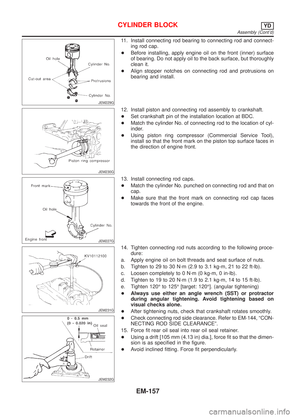
11. Install connecting rod bearing to connecting rod and connect-
ing rod cap.
+Before installing, apply engine oil on the front (inner) surface
of bearing. Do not apply oil to the back surface, but thoroughly
clean it.
+Align stopper notches on connecting rod and protrusions on
bearing and install.
JEM230G
12. Install piston and connecting rod assembly to crankshaft.
+Set crankshaft pin of the installation location at BDC.
+Match the cylinder No. of connecting rod to the location of cyl-
inder.
+Using piston ring compressor (Commercial Service Tool),
install so that the front mark on the piston top surface faces in
the direction of engine front.
JEM227G
13. Install connecting rod caps.
+Match the cylinder No. punched on connecting rod and that on
cap.
+Make sure that the front mark on connecting rod cap faces
towards the front of the engine.
JEM231G
JEM232G
14. Tighten connecting rod nuts according to the following proce-
dure:
a. Apply engine oil on bolt threads and seat surface of nuts.
b. Tighten to 29 to 30 N´m (2.9 to 3.1 kg-m, 21 to 22 ft-lb).
c. Loosen completely to 0 N´m (0 kg-m, 0 in-lb).
d. Tighten to 19 to 20 N´m (1.9 to 2.1 kg-m, 14 to 15 ft-lb).
e. Tighten 120É to 125É [target: 120É]. (angular tightening)
+Always use either an angle wrench (SST) or protractor
during angular tightening. Avoid tightening based on
visual checks alone.
+After tightening nuts, check that crankshaft rotates smoothly.
+Check connecting rod side clearance. Refer to EM-144, ªCON-
NECTING ROD SIDE CLEARANCEº.
15. Force fit rear oil seal into rear oil seal retainer.
+Using a drift [105 mm (4.13 in) dia.], force fit so that the dimen-
sion is as specified in the figure.
+Avoid inclined fitting. Force fit perpendicularly.
CYLINDER BLOCKYD
Assembly (Cont'd)
EM-157
Page 2292 of 2898
JEM233G
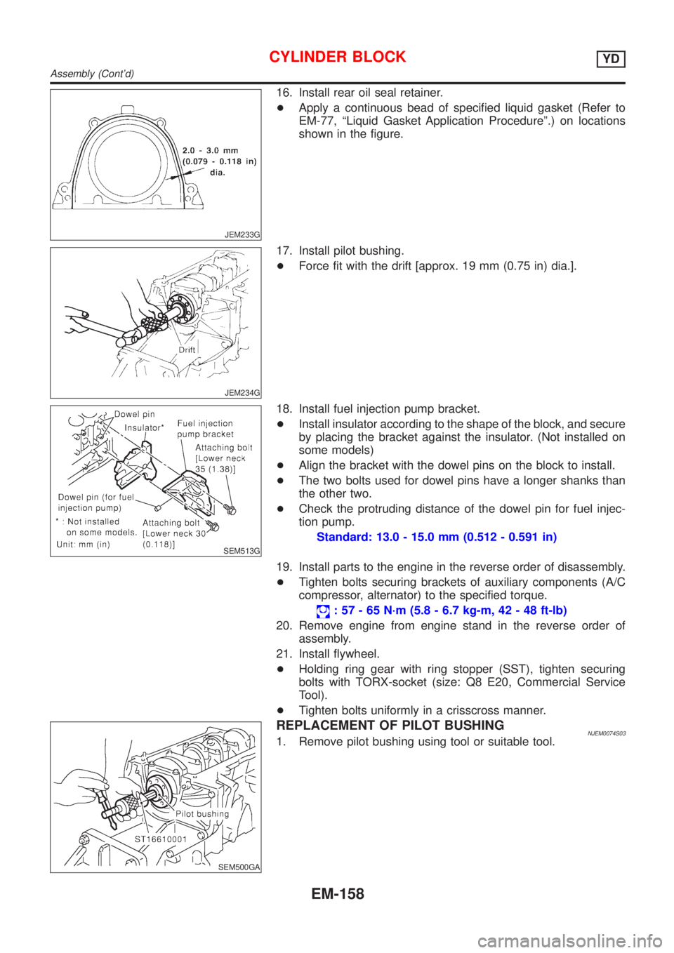
16. Install rear oil seal retainer.
+Apply a continuous bead of specified liquid gasket (Refer to
EM-77, ªLiquid Gasket Application Procedureº.) on locations
shown in the figure.
JEM234G
17. Install pilot bushing.
+Force fit with the drift [approx. 19 mm (0.75 in) dia.].
SEM513G
18. Install fuel injection pump bracket.
+Install insulator according to the shape of the block, and secure
by placing the bracket against the insulator. (Not installed on
some models)
+Align the bracket with the dowel pins on the block to install.
+The two bolts used for dowel pins have a longer shanks than
the other two.
+Check the protruding distance of the dowel pin for fuel injec-
tion pump.
Standard: 13.0 - 15.0 mm (0.512 - 0.591 in)
19. Install parts to the engine in the reverse order of disassembly.
+Tighten bolts securing brackets of auxiliary components (A/C
compressor, alternator) to the specified torque.
: 57 - 65 N´m (5.8 - 6.7 kg-m, 42 - 48 ft-lb)
20. Remove engine from engine stand in the reverse order of
assembly.
21. Install flywheel.
+Holding ring gear with ring stopper (SST), tighten securing
bolts with TORX-socket (size: Q8 E20, Commercial Service
Tool).
+Tighten bolts uniformly in a crisscross manner.
SEM500GA
REPLACEMENT OF PILOT BUSHINGNJEM0074S031. Remove pilot bushing using tool or suitable tool.
CYLINDER BLOCKYD
Assembly (Cont'd)
EM-158
Page 2294 of 2898
General SpecificationsNJEM0075
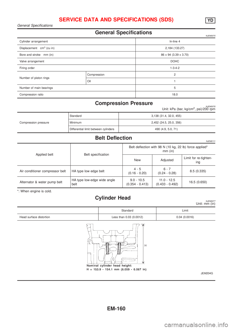
Cylinder arrangementIn-line 4
Displacement cm
3(cu in)2,184 (133.27)
Bore and stroke mm (in)86 x 94 (3.39 x 3.70)
Valve arrangementDOHC
Firing order1-3-4-2
Number of piston ringsCompression 2
Oil 1
Number of main bearings5
Compression ratio18.0
Compression PressureNJEM0076Unit: kPa (bar, kg/cm2, psi)/200 rpm
Compression pressureStandard 3,138 (31.4, 32.0, 455)
Minimum 2,452 (24.5, 25.0, 356)
Differential limit between cylinders 490 (4.9, 5.0, 71)
Belt DeflectionNJEM0111
Applied belt Belt specificationBelt deflection with 98 N (10 kg, 22 lb) force applied*
mm (in)
New AdjustedLimit for re-tighten-
ing
Air conditioner compressor belt HA type low edge belt4-5
(0.16 - 0.20)6-7
(0.24 - 0.28)8.5 (0.335)
Alternator & water pump beltHA type low-edge wide angle
belt9.0 - 10.5
(0.354 - 0.413)11.0 - 12.5
(0.433 - 0.492)16.5 (0.650)
*: When engine is cold.
Cylinder HeadNJEM0077Unit: mm (in)
Standard Limit
Head surface distortion Less than 0.03 (0.0012) 0.04 (0.0016)
JEM204G
SERVICE DATA AND SPECIFICATIONS (SDS)YD
General Specifications
EM-160
Page 2309 of 2898
SMA803A
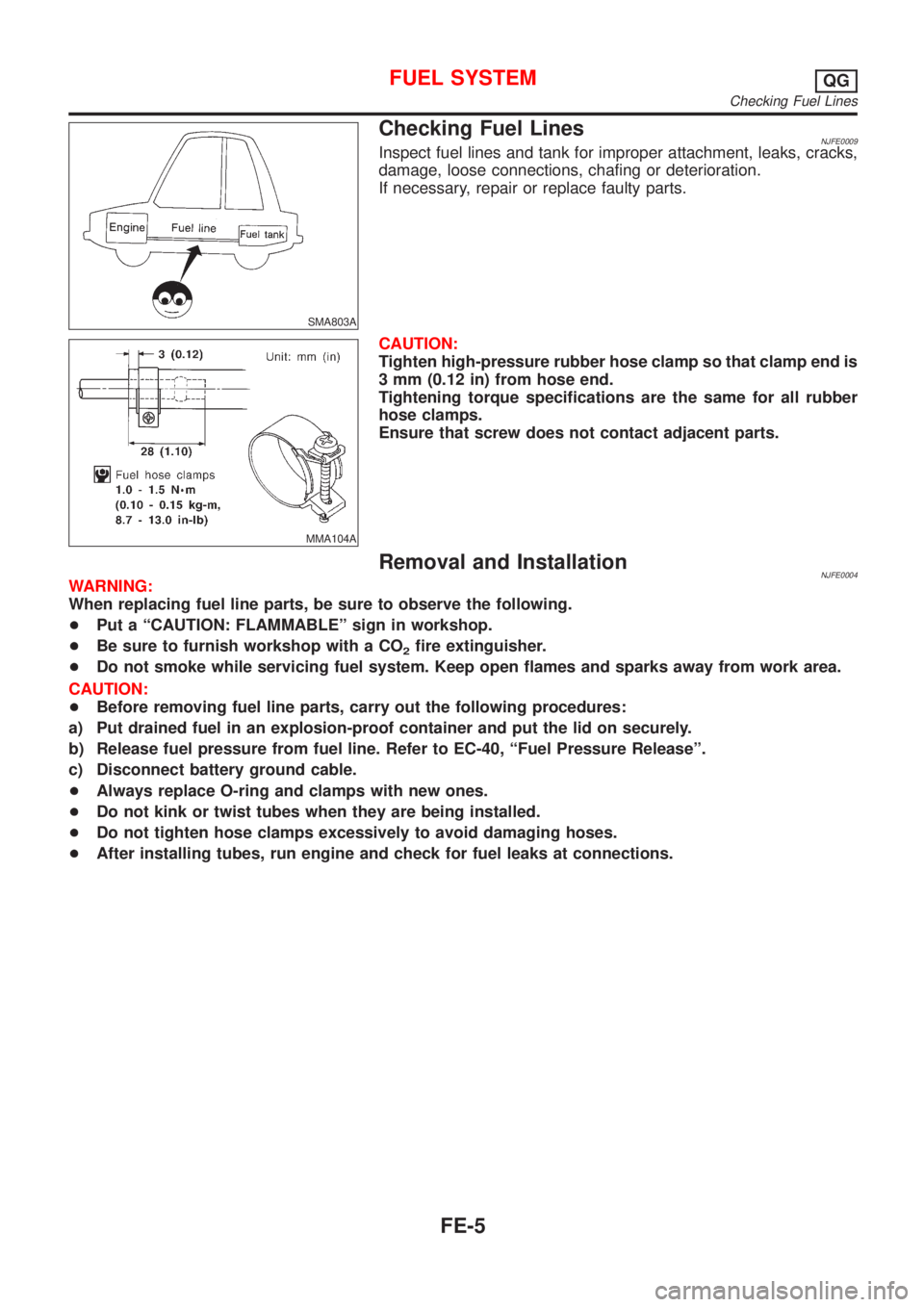
Checking Fuel LinesNJFE0009Inspect fuel lines and tank for improper attachment, leaks, cracks,
damage, loose connections, chafing or deterioration.
If necessary, repair or replace faulty parts.
MMA104A
CAUTION:
Tighten high-pressure rubber hose clamp so that clamp end is
3 mm (0.12 in) from hose end.
Tightening torque specifications are the same for all rubber
hose clamps.
Ensure that screw does not contact adjacent parts.
Removal and InstallationNJFE0004WARNING:
When replacing fuel line parts, be sure to observe the following.
+Put a ªCAUTION: FLAMMABLEº sign in workshop.
+Be sure to furnish workshop with a CO
2fire extinguisher.
+Do not smoke while servicing fuel system. Keep open flames and sparks away from work area.
CAUTION:
+Before removing fuel line parts, carry out the following procedures:
a) Put drained fuel in an explosion-proof container and put the lid on securely.
b) Release fuel pressure from fuel line. Refer to EC-40, ªFuel Pressure Releaseº.
c) Disconnect battery ground cable.
+Always replace O-ring and clamps with new ones.
+Do not kink or twist tubes when they are being installed.
+Do not tighten hose clamps excessively to avoid damaging hoses.
+After installing tubes, run engine and check for fuel leaks at connections.
FUEL SYSTEMQG
Checking Fuel Lines
FE-5
Page 2315 of 2898
SFE560AA
SFE657A
INSTALLATIONNJFE0006S02To install, reverse the removal procedure. Connect the quick con-
nector as follows:
+Align mating marks on tubes and connectors for correct instal-
lation.
+Insert tube into the center of the connector until you hear a
click.
SFE561AA
SFE658A
After connecting quick connector, make sure the connection is
firmly made using the following method.
+Pull on the fuel tube and connector to make sure they are firmly
connected.
+Start the engine, increase engine speed and verify that there
are no leaks.
FUEL SYSTEMQG
Fuel Tank (Cont'd)
FE-11
Page 2319 of 2898
SMA211A
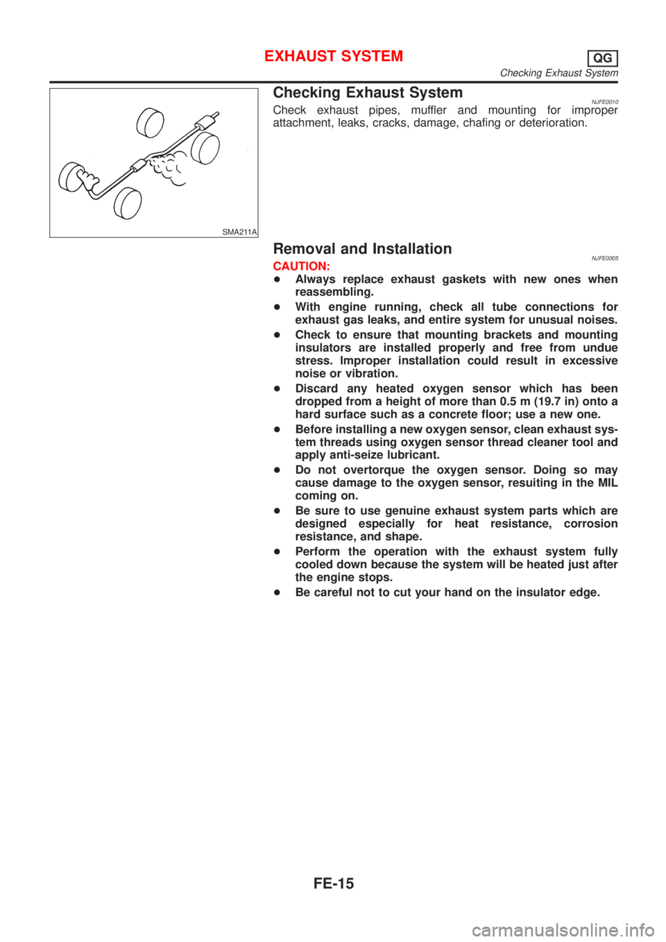
Checking Exhaust SystemNJFE0010Check exhaust pipes, muffler and mounting for improper
attachment, leaks, cracks, damage, chafing or deterioration.
Removal and InstallationNJFE0005CAUTION:
+Always replace exhaust gaskets with new ones when
reassembling.
+With engine running, check all tube connections for
exhaust gas leaks, and entire system for unusual noises.
+Check to ensure that mounting brackets and mounting
insulators are installed properly and free from undue
stress. Improper installation could result in excessive
noise or vibration.
+Discard any heated oxygen sensor which has been
dropped from a height of more than 0.5 m (19.7 in) onto a
hard surface such as a concrete floor; use a new one.
+Before installing a new oxygen sensor, clean exhaust sys-
tem threads using oxygen sensor thread cleaner tool and
apply anti-seize lubricant.
+Do not overtorque the oxygen sensor. Doing so may
cause damage to the oxygen sensor, resuiting in the MIL
coming on.
+Be sure to use genuine exhaust system parts which are
designed especially for heat resistance, corrosion
resistance, and shape.
+Perform the operation with the exhaust system fully
cooled down because the system will be heated just after
the engine stops.
+Be careful not to cut your hand on the insulator edge.
EXHAUST SYSTEMQG
Checking Exhaust System
FE-15
Page 2323 of 2898
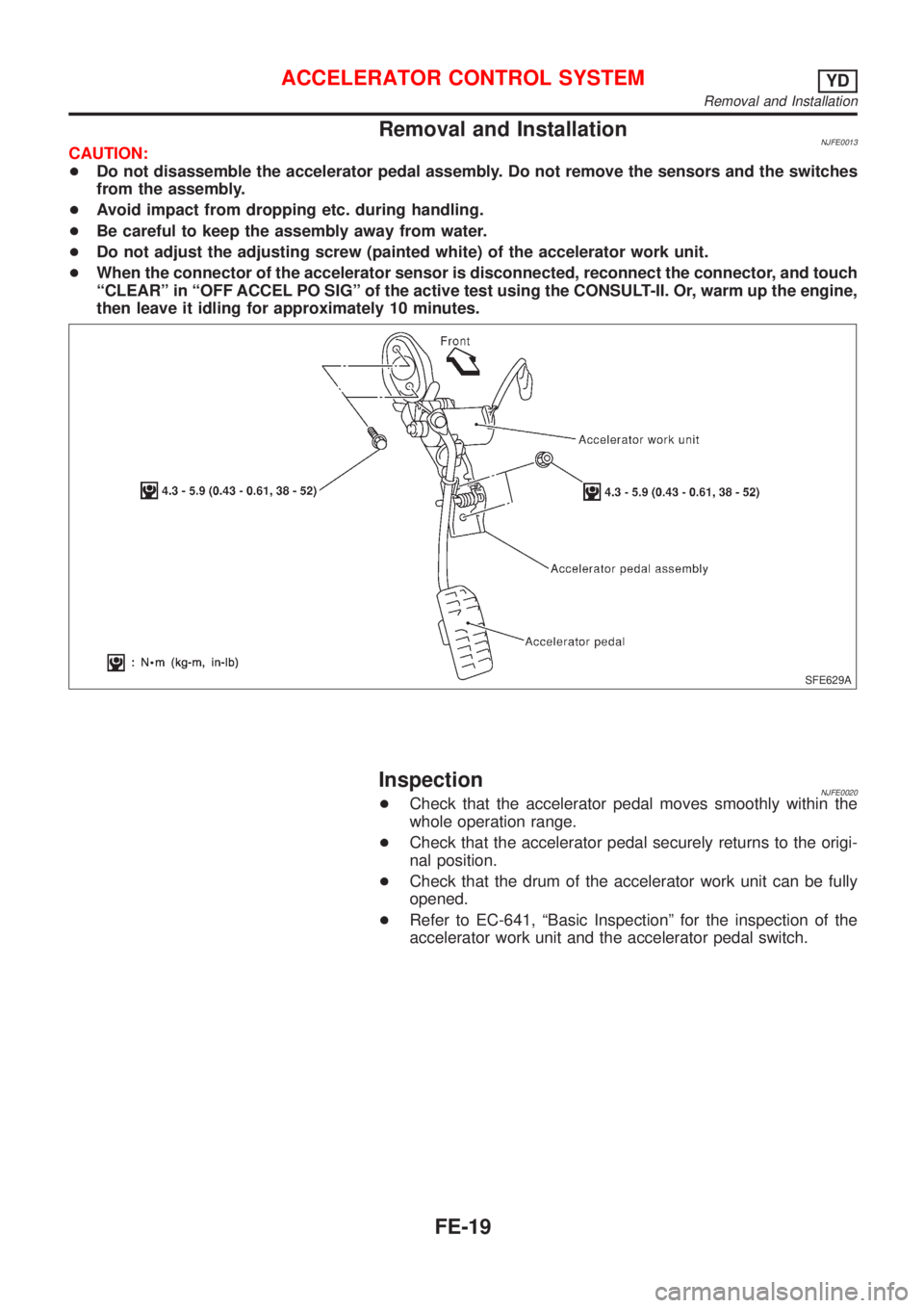
Removal and InstallationNJFE0013CAUTION:
+Do not disassemble the accelerator pedal assembly. Do not remove the sensors and the switches
from the assembly.
+Avoid impact from dropping etc. during handling.
+Be careful to keep the assembly away from water.
+Do not adjust the adjusting screw (painted white) of the accelerator work unit.
+When the connector of the accelerator sensor is disconnected, reconnect the connector, and touch
ªCLEARº in ªOFF ACCEL PO SIGº of the active test using the CONSULT-II. Or, warm up the engine,
then leave it idling for approximately 10 minutes.
SFE629A
InspectionNJFE0020+Check that the accelerator pedal moves smoothly within the
whole operation range.
+Check that the accelerator pedal securely returns to the origi-
nal position.
+Check that the drum of the accelerator work unit can be fully
opened.
+Refer to EC-641, ªBasic Inspectionº for the inspection of the
accelerator work unit and the accelerator pedal switch.
ACCELERATOR CONTROL SYSTEMYD
Removal and Installation
FE-19