2001 NISSAN ALMERA engine
[x] Cancel search: enginePage 2379 of 2898
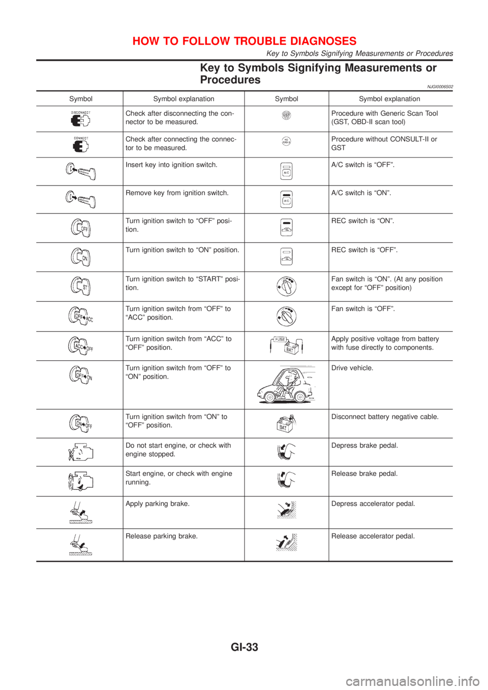
Key to Symbols Signifying Measurements or
Procedures
NJGI0006S02
Symbol Symbol explanation Symbol Symbol explanation
Check after disconnecting the con-
nector to be measured.Procedure with Generic Scan Tool
(GST, OBD-II scan tool)
Check after connecting the connec-
tor to be measured.Procedure without CONSULT-II or
GST
Insert key into ignition switch.A/C switch is ªOFFº.
Remove key from ignition switch.A/C switch is ªONº.
Turn ignition switch to ªOFFº posi-
tion.REC switch is ªONº.
Turn ignition switch to ªONº position.REC switch is ªOFFº.
Turn ignition switch to ªSTARTº posi-
tion.Fan switch is ªONº. (At any position
except for ªOFFº position)
Turn ignition switch from ªOFFº to
ªACCº position.Fan switch is ªOFFº.
Turn ignition switch from ªACCº to
ªOFFº position.Apply positive voltage from battery
with fuse directly to components.
Turn ignition switch from ªOFFº to
ªONº position.Drive vehicle.
Turn ignition switch from ªONº to
ªOFFº position.Disconnect battery negative cable.
Do not start engine, or check with
engine stopped.Depress brake pedal.
Start engine, or check with engine
running.Release brake pedal.
Apply parking brake.Depress accelerator pedal.
Release parking brake.Release accelerator pedal.
HOW TO FOLLOW TROUBLE DIAGNOSES
Key to Symbols Signifying Measurements or Procedures
GI-33
Page 2380 of 2898
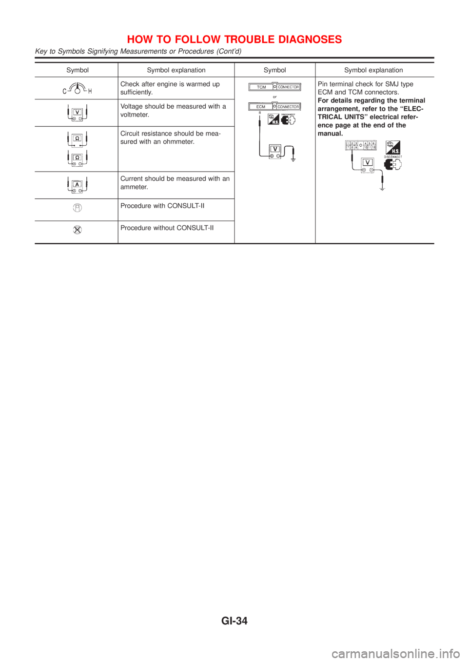
Symbol Symbol explanation Symbol Symbol explanation
Check after engine is warmed up
sufficiently.Pin terminal check for SMJ type
ECM and TCM connectors.
For details regarding the terminal
arrangement, refer to the ªELEC-
TRICAL UNITSº electrical refer-
ence page at the end of the
manual.
Voltage should be measured with a
voltmeter.
Circuit resistance should be mea-
sured with an ohmmeter.
Current should be measured with an
ammeter.
Procedure with CONSULT-II
Procedure without CONSULT-II
HOW TO FOLLOW TROUBLE DIAGNOSES
Key to Symbols Signifying Measurements or Procedures (Cont'd)
GI-34
Page 2381 of 2898
NJGI0007
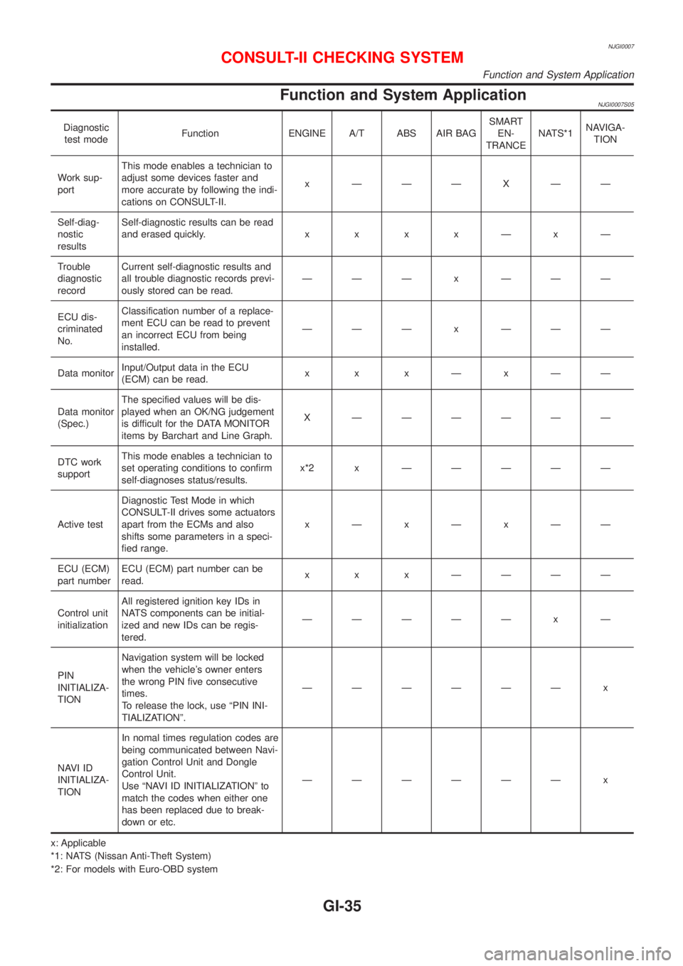
Function and System ApplicationNJGI0007S05
Diagnostic
test modeFunction ENGINE A/T ABS AIR BAGSMART
EN-
TRANCENATS*1NAVIGA-
TION
Work sup-
portThis mode enables a technician to
adjust some devices faster and
more accurate by following the indi-
cations on CONSULT-II.x ÐÐÐXÐÐ
Self-diag-
nostic
resultsSelf-diagnostic results can be read
and erased quickly.x x x xÐxÐ
Trouble
diagnostic
recordCurrent self-diagnostic results and
all trouble diagnostic records previ-
ously stored can be read.ÐÐÐ x ÐÐÐ
ECU dis-
criminated
No.Classification number of a replace-
ment ECU can be read to prevent
an incorrect ECU from being
installed.ÐÐÐ x ÐÐÐ
Data monitorInput/Output data in the ECU
(ECM) can be read.x x xÐxÐÐ
Data monitor
(Spec.)The specified values will be dis-
played when an OK/NG judgement
is difficult for the DATA MONITOR
items by Barchart and Line Graph.X ÐÐÐÐÐÐ
DTC work
supportThis mode enables a technician to
set operating conditions to confirm
self-diagnoses status/results.x*2x ÐÐÐÐÐ
Active testDiagnostic Test Mode in which
CONSULT-II drives some actuators
apart from the ECMs and also
shifts some parameters in a speci-
fied range.xÐxÐxÐÐ
ECU (ECM)
part numberECU (ECM) part number can be
read.x x x ÐÐÐÐ
Control unit
initializationAll registered ignition key IDs in
NATS components can be initial-
ized and new IDs can be regis-
tered.ÐÐÐÐÐ x Ð
PIN
INITIALIZA-
TIONNavigation system will be locked
when the vehicle's owner enters
the wrong PIN five consecutive
times.
To release the lock, use ªPIN INI-
TIALIZATIONº.ÐÐÐÐÐÐ x
NAVI ID
INITIALIZA-
TIONIn nomal times regulation codes are
being communicated between Navi-
gation Control Unit and Dongle
Control Unit.
Use ªNAVI ID INITIALIZATIONº to
match the codes when either one
has been replaced due to break-
down or etc.ÐÐÐÐÐÐ x
x: Applicable
*1: NATS (Nissan Anti-Theft System)
*2: For models with Euro-OBD system
CONSULT-II CHECKING SYSTEM
Function and System Application
GI-35
Page 2384 of 2898
NJGI0008
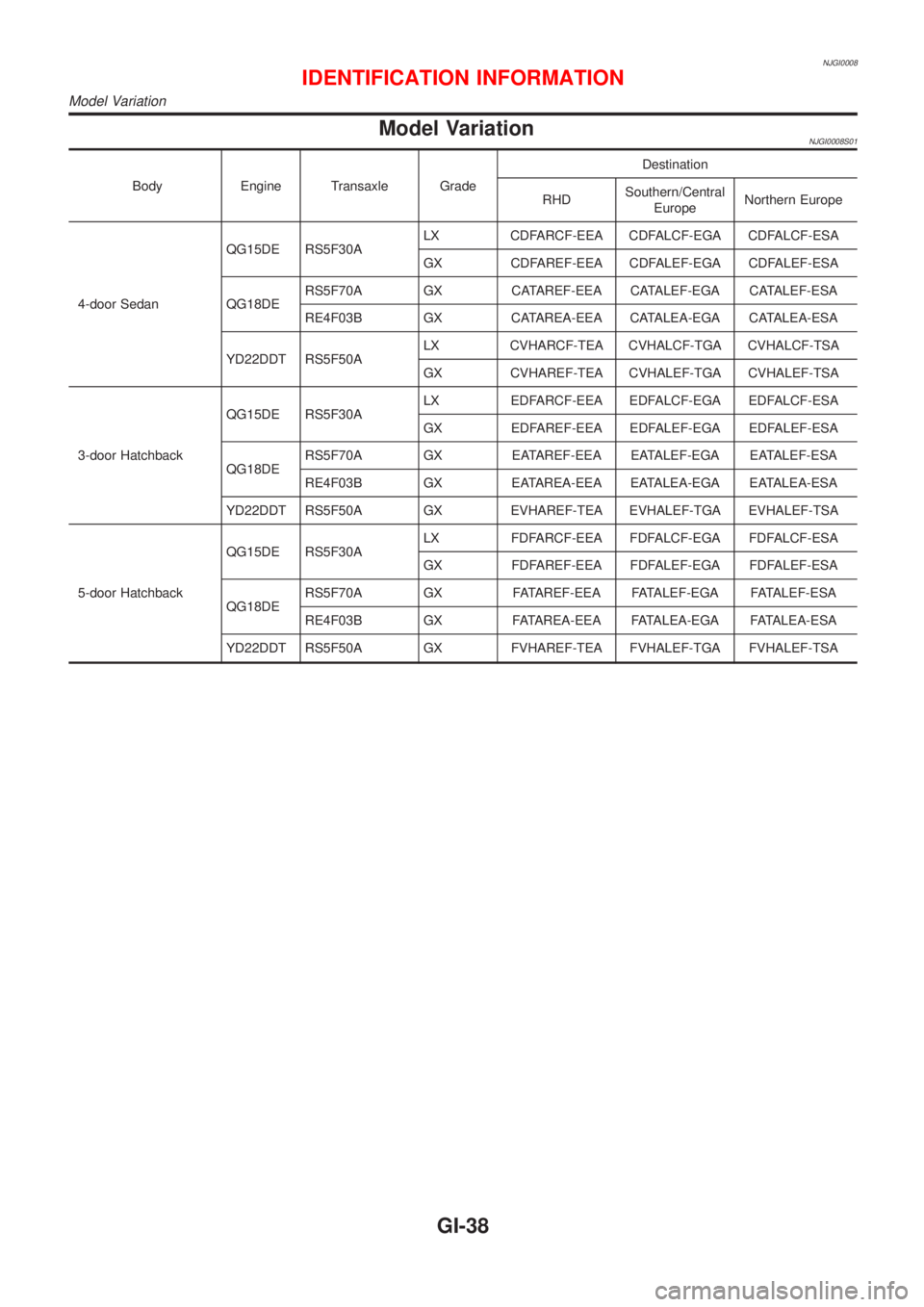
Model VariationNJGI0008S01
Body Engine Transaxle GradeDestination
RHDSouthern/Central
EuropeNorthern Europe
4-door SedanQG15DE RS5F30ALX CDFARCF-EEA CDFALCF-EGA CDFALCF-ESA
GX CDFAREF-EEA CDFALEF-EGA CDFALEF-ESA
QG18DERS5F70A GX CATAREF-EEA CATALEF-EGA CATALEF-ESA
RE4F03B GX CATAREA-EEA CATALEA-EGA CATALEA-ESA
YD22DDT RS5F50ALX CVHARCF-TEA CVHALCF-TGA CVHALCF-TSA
GX CVHAREF-TEA CVHALEF-TGA CVHALEF-TSA
3-door HatchbackQG15DE RS5F30ALX EDFARCF-EEA EDFALCF-EGA EDFALCF-ESA
GX EDFAREF-EEA EDFALEF-EGA EDFALEF-ESA
QG18DERS5F70A GX EATAREF-EEA EATALEF-EGA EATALEF-ESA
RE4F03B GX EATAREA-EEA EATALEA-EGA EATALEA-ESA
YD22DDT RS5F50A GX EVHAREF-TEA EVHALEF-TGA EVHALEF-TSA
5-door HatchbackQG15DE RS5F30ALX FDFARCF-EEA FDFALCF-EGA FDFALCF-ESA
GX FDFAREF-EEA FDFALEF-EGA FDFALEF-ESA
QG18DERS5F70A GX FATAREF-EEA FATALEF-EGA FATALEF-ESA
RE4F03B GX FATAREA-EEA FATALEA-EGA FATALEA-ESA
YD22DDT RS5F50A GX FVHAREF-TEA FVHALEF-TGA FVHALEF-TSA
IDENTIFICATION INFORMATION
Model Variation
GI-38
Page 2387 of 2898
SGI117A
SGI118A
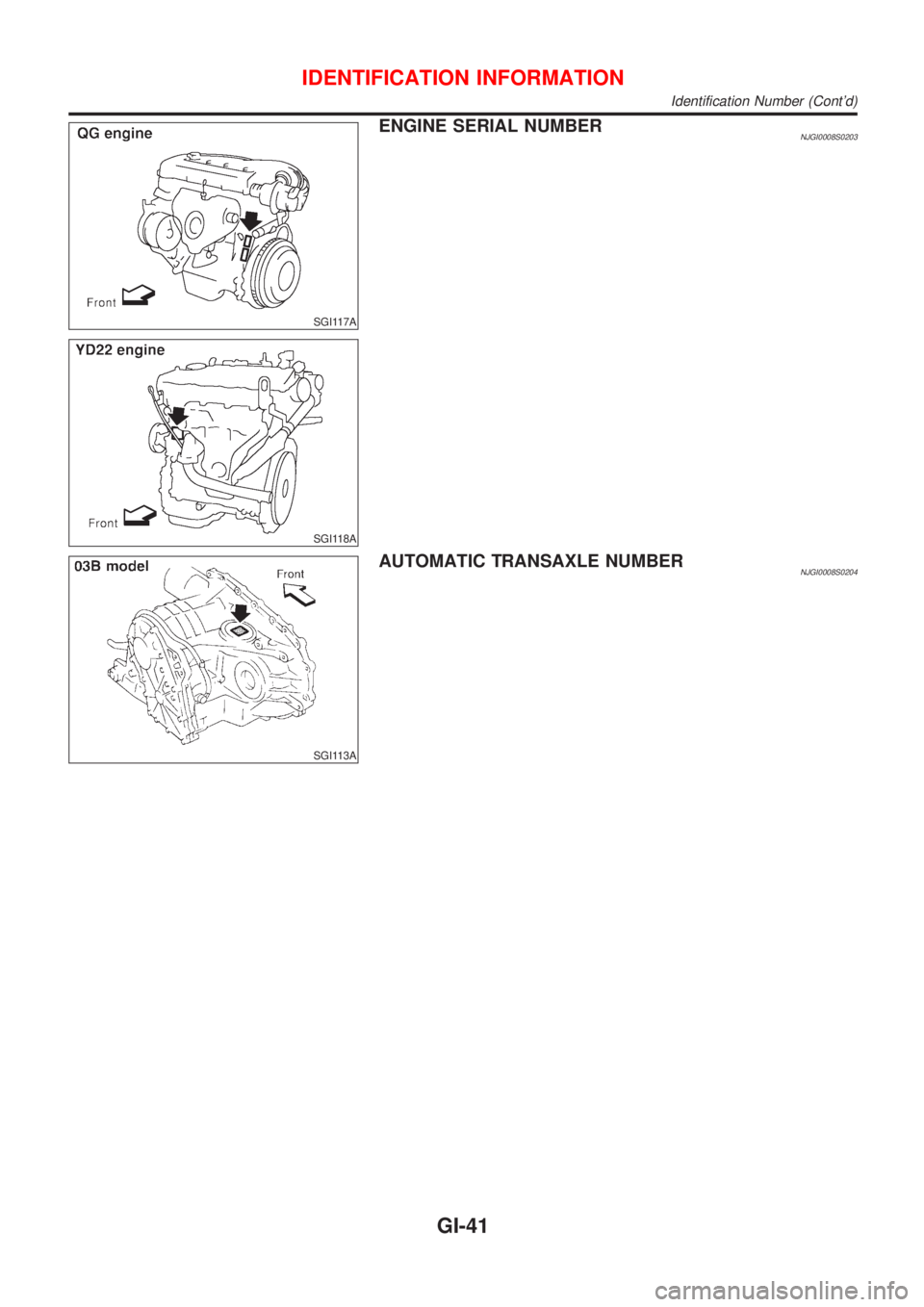
ENGINE SERIAL NUMBERNJGI0008S0203
SGI113A
AUTOMATIC TRANSAXLE NUMBERNJGI0008S0204
IDENTIFICATION INFORMATION
Identification Number (Cont'd)
GI-41
Page 2396 of 2898
NJGI0011
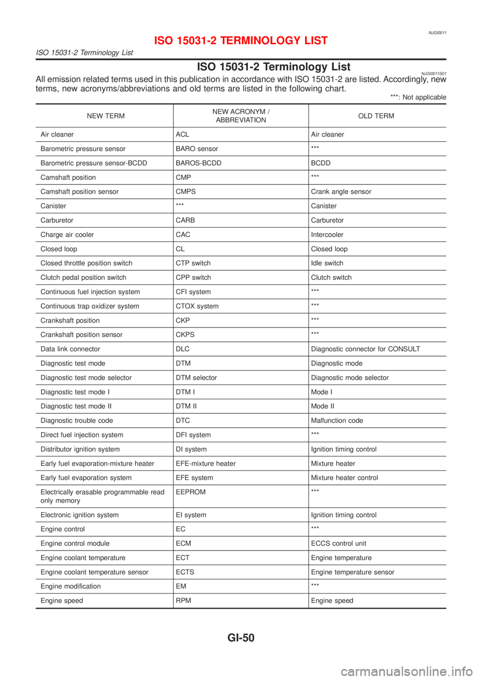
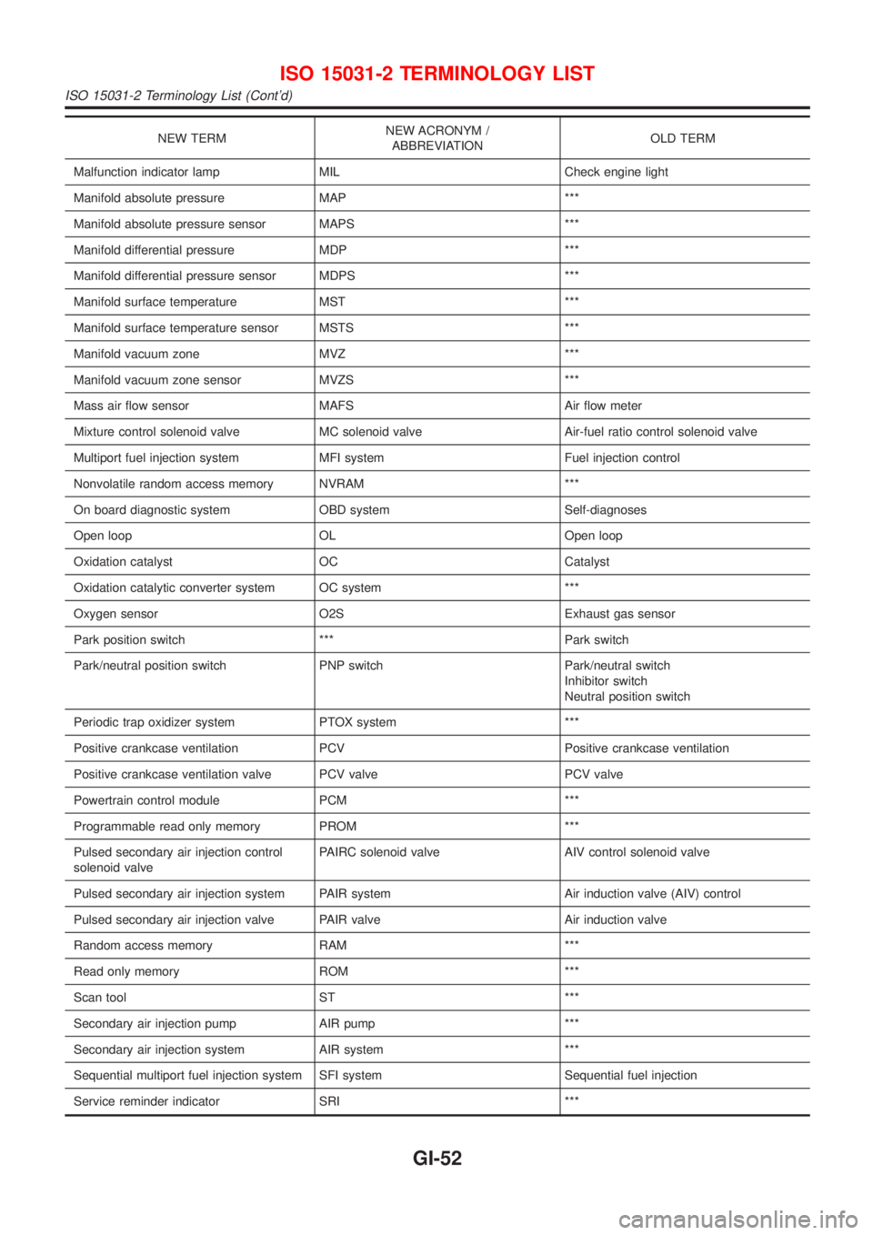
ISO 15031-2 Terminology ListNJGI0011S01All emission related terms used in this publication in accordance with ISO 15031-2 are listed. Accordingly, new
terms, new acronyms/abbreviations and old terms are listed in the following chart.
***: Not applicable
NEW TERMNEW ACRONYM /
ABBREVIATIONOLD TERM
Air cleaner ACL Air cleaner
Barometric pressure sensor BARO sensor ***
Barometric pressure sensor-BCDD BAROS-BCDD BCDD
Camshaft position CMP ***
Camshaft position sensor CMPS Crank angle sensor
Canister *** Canister
Carburetor CARB Carburetor
Charge air cooler CAC Intercooler
Closed loop CL Closed loop
Closed throttle position switch CTP switch Idle switch
Clutch pedal position switch CPP switch Clutch switch
Continuous fuel injection system CFI system ***
Continuous trap oxidizer system CTOX system ***
Crankshaft position CKP ***
Crankshaft position sensor CKPS ***
Data link connector DLC Diagnostic connector for CONSULT
Diagnostic test mode DTM Diagnostic mode
Diagnostic test mode selector DTM selector Diagnostic mode selector
Diagnostic test mode I DTM I Mode I
Diagnostic test mode II DTM II Mode II
Diagnostic trouble code DTC Malfunction code
Direct fuel injection system DFI system ***
Distributor ignition system DI system Ignition timing control
Early fuel evaporation-mixture heater EFE-mixture heater Mixture heater
Early fuel evaporation system EFE system Mixture heater control
Electrically erasable programmable read
only memoryEEPROM ***
Electronic ignition system EI system Ignition timing control
Engine control EC ***
Engine control module ECM ECCS control unit
Engine coolant temperature ECT Engine temperature
Engine coolant temperature sensor ECTS Engine temperature sensor
Engine modification EM ***
Engine speed RPM Engine speed
ISO 15031-2 TERMINOLOGY LIST
ISO 15031-2 Terminology List
GI-50
Page 2398 of 2898
NEW TERMNEW ACRONYM /
ABBREVIATIONOLD TERM
Malfunction indicator lamp MIL Check engine light
Manifold absolute pressure MAP ***
Manifold absolute pressure sensor MAPS ***
Manifold differential pressure MDP ***
Manifold differential pressure sensor MDPS ***
Manifold surface temperature MST ***
Manifold surface temperature sensor MSTS ***
Manifold vacuum zone MVZ ***
Manifold vacuum zone sensor MVZS ***
Mass air flow sensor MAFS Air flow meter
Mixture control solenoid valve MC solenoid valve Air-fuel ratio control solenoid valve
Multiport fuel injection system MFI system Fuel injection control
Nonvolatile random access memory NVRAM ***
On board diagnostic system OBD system Self-diagnoses
Open loop OL Open loop
Oxidation catalyst OC Catalyst
Oxidation catalytic converter system OC system ***
Oxygen sensor O2S Exhaust gas sensor
Park position switch *** Park switch
Park/neutral position switch PNP switch Park/neutral switch
Inhibitor switch
Neutral position switch
Periodic trap oxidizer system PTOX system ***
Positive crankcase ventilation PCV Positive crankcase ventilation
Positive crankcase ventilation valve PCV valve PCV valve
Powertrain control module PCM ***
Programmable read only memory PROM ***
Pulsed secondary air injection control
solenoid valvePAIRC solenoid valve AIV control solenoid valve
Pulsed secondary air injection system PAIR system Air induction valve (AIV) control
Pulsed secondary air injection valve PAIR valve Air induction valve
Random access memory RAM ***
Read only memory ROM ***
Scan tool ST ***
Secondary air injection pump AIR pump ***
Secondary air injection system AIR system ***
Sequential multiport fuel injection system SFI system Sequential fuel injection
Service reminder indicator SRI ***
ISO 15031-2 TERMINOLOGY LIST
ISO 15031-2 Terminology List (Cont'd)
GI-52
Page 2401 of 2898
HEATER &
AIR CONDITIONER
SECTION
HA
CONTENTS
PRECAUTIONS...............................................................2
Supplemental Restraint System (SRS)²AIR
BAG²and²SEAT BELT PRE-TENSIONER²...............2
Precautions for Working with HFC-134a (R-134a) .....2
General Refrigerant Precautions .................................2
Precautions for Refrigerant Connection ......................3
Precautions for Servicing Compressor ........................5
Precautions for Service Equipment .............................6
Wiring Diagrams and Trouble Diagnosis .....................8
PREPARATION...............................................................9
Special Service Tools ..................................................9
HFC-134a (R-134a) Service Tools and
Equipment .................................................................. 11
DESCRIPTION...............................................................13
Refrigeration System .................................................13
CSV613 Variable Displacement Compressor............14
Component Layout ....................................................18
Control Operation ......................................................19
Discharge Air Flow.....................................................20
System Description ....................................................21
TROUBLE DIAGNOSES................................................22
Component Location..................................................22
Wiring Diagram - Heater............................................24
Circuit Diagram - Air Conditioner...............................26
Wiring Diagram - A/C, M - .........................................27
How to Perform Trouble Diagnoses for Quick
and Accurate Repair ..................................................33
Operational Check .....................................................34
Intake Door ................................................................36
Mode Door .................................................................40Air Mix Door ...............................................................42
Max Hot Door (For Scandinavia and Cold Spec
Models) ......................................................................44
Blower Motor..............................................................48
Magnet Clutch............................................................55
Insufficient Cooling ....................................................68
Insufficient Heating ....................................................76
Noise ..........................................................................77
SERVICE PROCEDURE................................................78
HFC-134a (R-134a) Service Procedure ....................78
Maintenance of Lubricant Quantity in
Compressor ...............................................................80
Compressor ...............................................................83
Compressor Clutch - CSV613 (CALSONIC
make) .........................................................................84
Heater & Cooling Unit (Heater Core) ........................88
A/C Evaporator ..........................................................88
Blower Unit ................................................................89
Refrigerant Lines .......................................................91
Belt .............................................................................95
Idle Air Control Valve (IACV) - Auxiliary Air
Control (AAC) Valve ..................................................96
Ventilation Air Filter ....................................................96
SERVICE DATA AND SPECIFICATIONS (SDS).........97
Compressor ...............................................................97
Lubricant ....................................................................97
Refrigerant .................................................................97
Engine Idling Speed (When A/C is On).....................97
Belt Tension ...............................................................97