Page 1025 of 2493

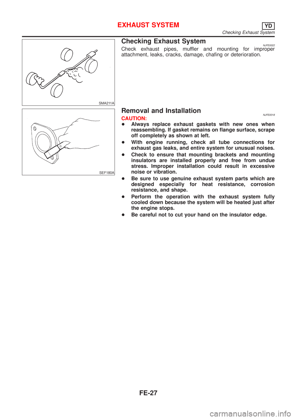
SMA211A
Checking Exhaust SystemNJFE0022Check exhaust pipes, muffler and mounting for improper
attachment, leaks, cracks, damage, chafing or deterioration.
SEF180A
Removal and InstallationNJFE0018CAUTION:
+Always replace exhaust gaskets with new ones when
reassembling. If gasket remains on flange surface, scrape
off completely as shown at left.
+With engine running, check all tube connections for
exhaust gas leaks, and entire system for unusual noises.
+Check to ensure that mounting brackets and mounting
insulators are installed properly and free from undue
stress. Improper installation could result in excessive
noise or vibration.
+Be sure to use genuine exhaust system parts which are
designed especially for heat resistance, corrosion
resistance, and shape.
+Perform the operation with the exhaust system fully
cooled down because the system will be heated just after
the engine stops.
+Be careful not to cut your hand on the insulator edge.
EXHAUST SYSTEMYD
Checking Exhaust System
FE-27
Page 1035 of 2493

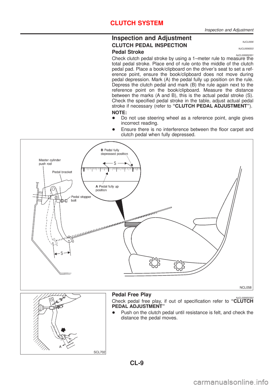
Inspection and AdjustmentNJCL0006CLUTCH PEDAL INSPECTIONNJCL0006S03Pedal StrokeNJCL0006S0301Check clutch pedal stroke by using a 1±meter rule to measure the
total pedal stroke. Place end of rule onto the middle of the clutch
pedal pad. Place a book/clipboard on the driver's seat to set a ref-
erence point, ensure the book/clipboard does not move during
pedal depression. Mark (A) the pedal fully up position on the rule.
Depress the clutch pedal and mark (B) the rule again next to the
reference point on the book/clipboard. Measure the distance
between the marks (A and B), this is the actual pedal stroke (S).
Check the specified pedal stroke in the table, adjust actual pedal
stroke if necessary (refer toªCLUTCH PEDAL ADJUSTMENTº).
NOTE:
+Do not use steering wheel as a reference point, angle gives
incorrect reading.
+Ensure there is no interference between the floor carpet and
clutch pedal when fully depressed.
NCL058
SCL702
Pedal Free PlayNJCL0006S0302Check pedal free play, if out of specification refer toªCLUTCH
PEDAL ADJUSTMENTº
+Push on the clutch pedal until resistance is felt, and check the
distance the pedal moves.
CLUTCH SYSTEM
Inspection and Adjustment
CL-9
Page 1036 of 2493

CLUTCH PEDAL ADJUSTMENTNJCL0006S04Pedal StrokeNJCL0006S04011. Loosen the pedal stopper bolt completely (so there is no con-
tact between pedal and stopper bolt).
2. Adjust pedal stroke to the specified value with the master cyl-
inder push rod.
3. Adjust the pedal stopper bolt until it is just in contact with the
pedal, then tighten the lock nut.
4. Once stroke is set to specification, adjust clutch pedal free
play.
Pedal stroke ªSº.
Refer to ªSDSº, CL-24.
Pedal Free PlayNJCL0006S04021. Adjust pedal free play to the specified value with the master
cylinder push rod.
2. Tighten lock nut of the master cylinder push rod.
+Push on the clutch pedal until resistance is felt, and check the
distance the pedal moves.
Pedal free play ªAº.
Refer to ªSDSº, CL-24.
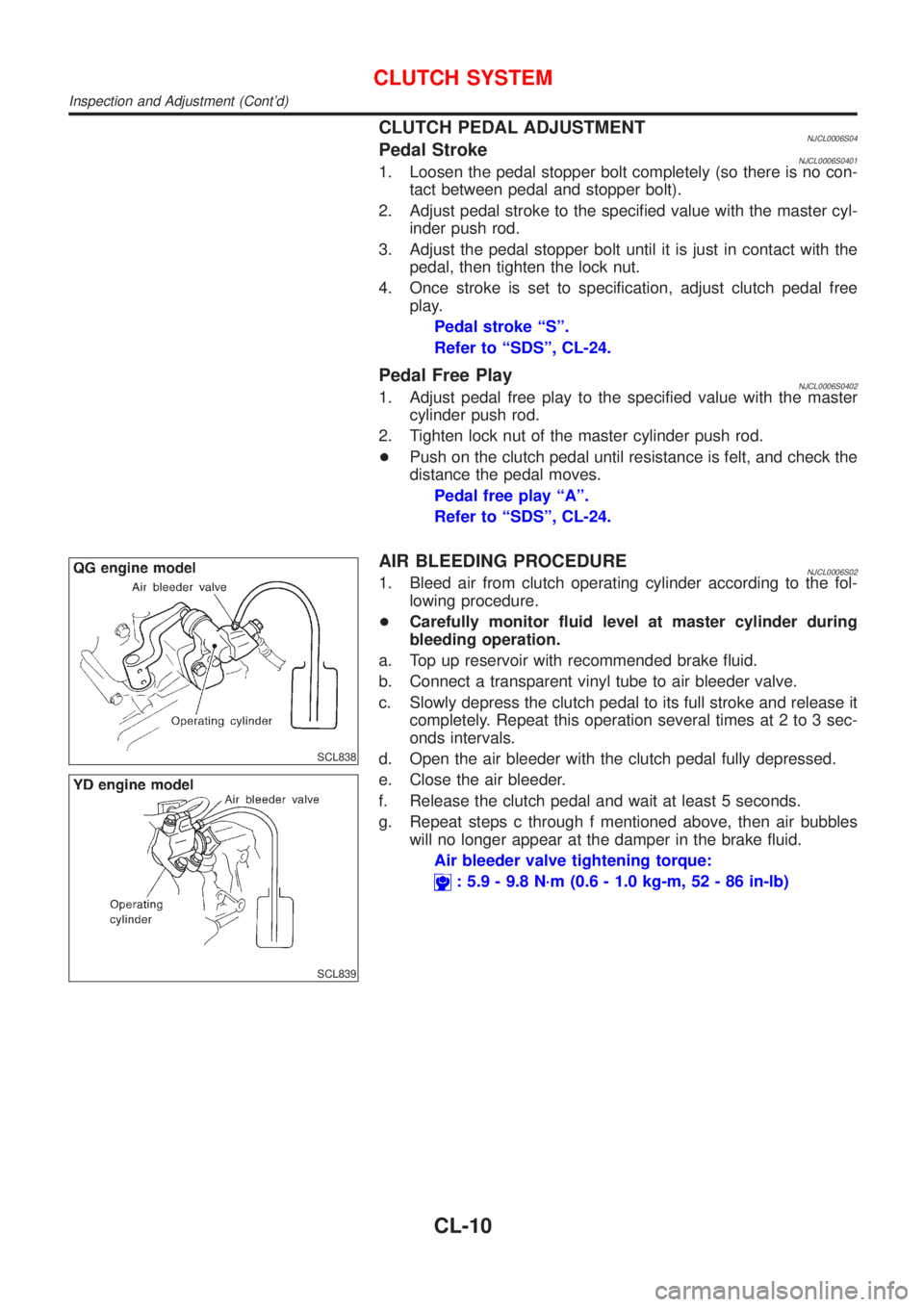
SCL838
SCL839
AIR BLEEDING PROCEDURENJCL0006S021. Bleed air from clutch operating cylinder according to the fol-
lowing procedure.
+Carefully monitor fluid level at master cylinder during
bleeding operation.
a. Top up reservoir with recommended brake fluid.
b. Connect a transparent vinyl tube to air bleeder valve.
c. Slowly depress the clutch pedal to its full stroke and release it
completely. Repeat this operation several times at 2 to 3 sec-
onds intervals.
d. Open the air bleeder with the clutch pedal fully depressed.
e. Close the air bleeder.
f. Release the clutch pedal and wait at least 5 seconds.
g. Repeat steps c through f mentioned above, then air bubbles
will no longer appear at the damper in the brake fluid.
Air bleeder valve tightening torque:
: 5.9 - 9.8 N´m (0.6 - 1.0 kg-m, 52 - 86 in-lb)
CLUTCH SYSTEM
Inspection and Adjustment (Cont'd)
CL-10
Page 1190 of 2493

Rear Internal Gear, Forward Clutch Hub and
Overrun Clutch Hub .................................................410
Output Shaft, Idler Gear, Reduction Pinion Gear
and Bearing Retainer...............................................414
Band Servo Piston Assembly ..................................419
Final Drive................................................................424
ASSEMBLY..................................................................428
Assembly (1) ............................................................428
Adjustment (1) .........................................................429
Assembly (2) ............................................................434
Adjustment (2) .........................................................438
Assembly (3) ............................................................442
Assembly (4) ............................................................444
SERVICE DATA AND SPECIFICATIONS (SDS).......449
General Specifications .............................................449
Shift Schedule..........................................................449
Stall Revolution ........................................................450
Line Pressure...........................................................450
Control Valves..........................................................450Clutch and Brakes ...................................................451
Clutch and Brake Return Springs............................452
Oil Pump ..................................................................453
Input Shaft ...............................................................453
Planetary Carrier......................................................453
Final Drive................................................................453
Reduction Pinion Gear ............................................455
Output Shaft.............................................................456
Bearing Retainer ......................................................457
Total End Play..........................................................457
Reverse Clutch End Play ........................................457
Accumulator .............................................................457
Band Servo ..............................................................458
Removal and Installation .........................................458
Shift Solenoid Valves ...............................................458
Resistance ...............................................................458
ATF Temp. Sensor ...................................................458
Revolution Sensor ...................................................458
Dropping Resistor ....................................................458
CONTENTS(Cont'd)
AT-4
Page 1329 of 2493
Diagnostic ProcedureNJAT0065
1 CHECK VALVE RESISTANCE
1. Turn ignition switch to ªOFFº position.
2. Disconnect terminal cord assembly connector in engine compartment.
3. Check resistance between terminal 2 and ground.
Resistance:
20-30W
SAT900JA
OK or NG
OK©GO TO 2.
NG©1. Remove control valve assembly. Refer to AT-343.
2. Check the following items:
+Shift solenoid valve A
Refer to ªComponent Inspectionº, AT-145.
+Harness of terminal cord assembly for short or open
SHIFT SOLENOID VALVE AEXCEPT FOR EURO-OBD
Diagnostic Procedure
AT-143
Page 1331 of 2493
SAT021K
Component InspectionNJAT0066SHIFT SOLENOID VALVE ANJAT0066S01+For removal, refer to AT-343.
Resistance CheckNJAT0066S0101+Check resistance between two terminals.
Solenoid valve Terminal No.Resistance
(Approx.)
Shift solenoid
valve A2 Ground 20 - 30W
SAT022K
Operation CheckNJAT0066S0102+Check solenoid valve by listening for its operating sound while
applying battery voltage to the terminal and ground.
SHIFT SOLENOID VALVE AEXCEPT FOR EURO-OBD
Component Inspection
AT-145
Page 1335 of 2493
Diagnostic ProcedureNJAT0068
1 CHECK VALVE RESISTANCE
1. Turn ignition switch to ªOFFº position.
2. Disconnect terminal cord assembly connector in engine compartment.
3. Check resistance between terminal 1 and ground.
Resistance:
5-20W
SAT904JA
OK or NG
OK©GO TO 2.
NG©1. Remove control valve assembly. Refer to AT-343.
2. Check the following items:
+Shift solenoid valve B
Refer to ªComponent Inspectionº, AT-151.
+Harness of terminal cord assembly for short or open
SHIFT SOLENOID VALVE BEXCEPT FOR EURO-OBD
Diagnostic Procedure
AT-149
Page 1337 of 2493
SAT023K
Component InspectionNJAT0069SHIFT SOLENOID VALVE BNJAT0069S01+For removal, refer to AT-343.
Resistance CheckNJAT0069S0101+Check resistance between two terminals.
Solenoid valve Terminal No.Resistance
(Approx.)
Shift solenoid
valve B1 Ground 5 - 20W
SAT024K
Operation CheckNJAT0069S0102+Check solenoid valve by listening for its operating sound while
applying battery voltage to the terminal and ground.
SHIFT SOLENOID VALVE BEXCEPT FOR EURO-OBD
Component Inspection
AT-151