Page 588 of 2493

SEF069X
SEF605Y
SEF015Y
SEF560W
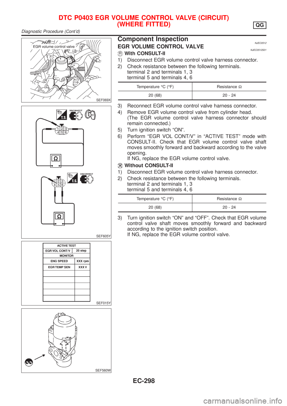
Component InspectionNJEC0233EGR VOLUME CONTROL VALVENJEC0233S01With CONSULT-II
1) Disconnect EGR volume control valve harness connector.
2) Check resistance between the following terminals.
terminal 2 and terminals 1, 3
terminal 5 and terminals 4, 6
Temperature ÉC (ÉF) ResistanceW
20 (68) 20 - 24
3) Reconnect EGR volume control valve harness connector.
4) Remove EGR volume control valve from cylinder head.
(The EGR volume control valve harness connector should
remain connected.)
5) Turn ignition switch ªONº.
6) Perform ªEGR VOL CONT/Vº in ªACTIVE TESTº mode with
CONSULT-II. Check that EGR volume control valve shaft
moves smoothly forward and backward according to the valve
opening.
If NG, replace the EGR volume control valve.
Without CONSULT-II
1) Disconnect EGR volume control valve harness connector.
2) Check resistance between the following terminals.
terminal 2 and terminals 1, 3
terminal 5 and terminals 4, 6
Temperature ÉC (ÉF) ResistanceW
20 (68) 20 - 24
3) Turn ignition switch ªONº and ªOFFº. Check that EGR volume
control valve shaft moves smoothly forward and backward
according to the ignition switch position.
If NG, replace the EGR volume control valve.
DTC P0400 EGR FUNCTION (CLOSED) (WHERE FITTED)QG
Diagnostic Procedure (Cont'd)
EC-292
Page 594 of 2493

SEF069X
SEF605Y
SEF015Y
SEF560W
Component InspectionNJEC0512EGR VOLUME CONTROL VALVENJEC0512S01With CONSULT-II
1) Disconnect EGR volume control valve harness connector.
2) Check resistance between the following terminals.
terminal 2 and terminals 1, 3
terminal 5 and terminals 4, 6
Temperature ÉC (ÉF) ResistanceW
20 (68) 20 - 24
3) Reconnect EGR volume control valve harness connector.
4) Remove EGR volume control valve from cylinder head.
(The EGR volume control valve harness connector should
remain connected.)
5) Turn ignition switch ªONº.
6) Perform ªEGR VOL CONT/Vº in ªACTIVE TESTº mode with
CONSULT-II. Check that EGR volume control valve shaft
moves smoothly forward and backward according to the valve
opening.
If NG, replace the EGR volume control valve.
Without CONSULT-II
1) Disconnect EGR volume control valve harness connector.
2) Check resistance between the following terminals.
terminal 2 and terminals 1, 3
terminal 5 and terminals 4, 6
Temperature ÉC (ÉF) ResistanceW
20 (68) 20 - 24
3) Turn ignition switch ªONº and ªOFFº. Check that EGR volume
control valve shaft moves smoothly forward and backward
according to the ignition switch position.
If NG, replace the EGR volume control valve.
DTC P0403 EGR VOLUME CONTROL VALVE (CIRCUIT)
(WHERE FITTED)
QG
Diagnostic Procedure (Cont'd)
EC-298
Page 616 of 2493
SEF605Y
SEF089X
Component InspectionNJEC0286IACV-AAC VALVENJEC0286S011) Disconnect IACV-AAC valve harness connector.
2) Check IACV-AAC valve resistance.
Condition Resistance
Terminal 2 and terminals 1, 3
20-24W[at 20ÉC (68ÉF)]
Terminal 5 and terminals 4, 6
3) Reconnect IACV-AAC valve harness connector.
4) Remove idle air adjusting unit assembly (IACV-AAC valve is
built-in) from engine.
(The IACV-AAC valve harness connector should remain con-
nected.)
5) Turn ignition switch ªONº and ªOFFº, and ensure the IACV-
AAC valve shaft smoothly moves forward and backward,
according to the ignition switch position.
If NG, replace the IACV-AAC valve.
DTC P0505 IDLE AIR CONTROL VALVE (IACV) Ð AUXILIARY AIR CONTROL
(AAC) VALVE
QG
Component Inspection
EC-320
Page 643 of 2493

SEF599K
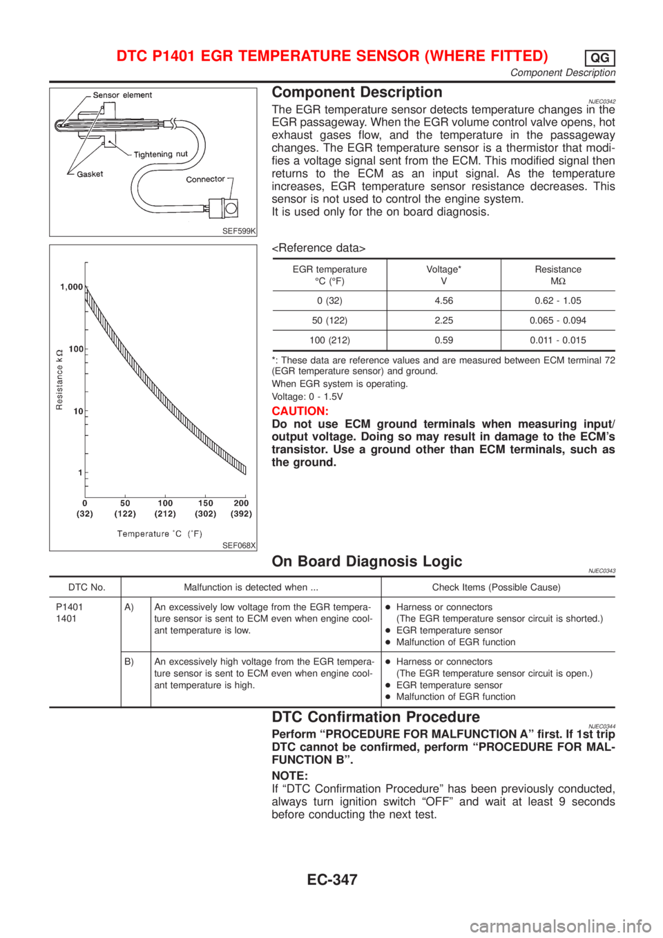
Component DescriptionNJEC0342The EGR temperature sensor detects temperature changes in the
EGR passageway. When the EGR volume control valve opens, hot
exhaust gases flow, and the temperature in the passageway
changes. The EGR temperature sensor is a thermistor that modi-
fies a voltage signal sent from the ECM. This modified signal then
returns to the ECM as an input signal. As the temperature
increases, EGR temperature sensor resistance decreases. This
sensor is not used to control the engine system.
It is used only for the on board diagnosis.
SEF068X
EGR temperature
ÉC (ÉF)Voltage*
VResistance
MW
0 (32) 4.56 0.62 - 1.05
50 (122) 2.25 0.065 - 0.094
100 (212) 0.59 0.011 - 0.015
*: These data are reference values and are measured between ECM terminal 72
(EGR temperature sensor) and ground.
When EGR system is operating.
Voltage: 0 - 1.5V
CAUTION:
Do not use ECM ground terminals when measuring input/
output voltage. Doing so may result in damage to the ECM's
transistor. Use a ground other than ECM terminals, such as
the ground.
On Board Diagnosis LogicNJEC0343
DTC No. Malfunction is detected when ... Check Items (Possible Cause)
P1401
1401A) An excessively low voltage from the EGR tempera-
ture sensor is sent to ECM even when engine cool-
ant temperature is low.+Harness or connectors
(The EGR temperature sensor circuit is shorted.)
+EGR temperature sensor
+Malfunction of EGR function
B) An excessively high voltage from the EGR tempera-
ture sensor is sent to ECM even when engine cool-
ant temperature is high.+Harness or connectors
(The EGR temperature sensor circuit is open.)
+EGR temperature sensor
+Malfunction of EGR function
DTC Confirmation ProcedureNJEC0344Perform ªPROCEDURE FOR MALFUNCTION Aº first. If 1st trip
DTC cannot be confirmed, perform ªPROCEDURE FOR MAL-
FUNCTION Bº.
NOTE:
If ªDTC Confirmation Procedureº has been previously conducted,
always turn ignition switch ªOFFº and wait at least 9 seconds
before conducting the next test.
DTC P1401 EGR TEMPERATURE SENSOR (WHERE FITTED)QG
Component Description
EC-347
Page 648 of 2493
4 CHECK EGR TEMPERATURE SENSOR
Refer to ªComponent Inspectionº, EC-352.
OK or NG
OK©GO TO 5.
NG©Replace EGR temperature sensor.
5 CHECK EGR VOLUME CONTROL VALVE
Refer to ªComponent Inspectionº, EC-359.
OK or NG
OK©GO TO 6.
NG©Replace EGR volume control valve.
6 CHECK INTERMITTENT INCIDENT
Perform ªTROUBLE DIAGNOSIS FOR INTERMITTENT INCIDENTº, EC-144.
©INSPECTION END
SEF611Y
SEF068X
Component InspectionNJEC0348EGR TEMPERATURE SENSORNJEC0348S01Check resistance change and resistance value.
EGR temperature
ÉC (ÉF)Voltage
VResistance
MW
0 (32) 4.56 0.62 - 1.05
50 (122) 2.25 0.065 - 0.094
100 (212) 0.59 0.011 - 0.015
If NG, replace EGR temperature sensor.
DTC P1401 EGR TEMPERATURE SENSOR (WHERE FITTED)QG
Diagnostic Procedure (Cont'd)
EC-352
Page 655 of 2493
5 CHECK EGR VOLUME CONTROL VALVE
Refer to ªCOMPONENT INSPECTIONº, EC-359.
OK or NG
OK©GO TO 6.
NG©Replace EGR volume control valve.
6 CHECK INTERMITTENT INCIDENT
Perform ªTROUBLE DIAGNOSIS FOR INTERMITTENT INCIDENTº, EC-144.
©INSPECTION END
SEF611Y
SEF068X
Component InspectionNJEC0354EGR TEMPERATURE SENSORNJEC0354S01Check resistance change and resistance value.
EGR temperature
ÉC (ÉF)Voltage
VResistance
MW
0 (32) 4.56 0.62 - 1.05
50 (122) 2.25 0.065 - 0.094
100 (212) 0.59 0.011 - 0.015
If NG, replace EGR temperature sensor.
DTC P1402 EGR FUNCTION (OPEN) (WHERE FITTED)QG
Diagnostic Procedure (Cont'd)
EC-359
Page 656 of 2493

SEF069X
SEF605Y
SEF015Y
SEF560W
EGR VOLUME CONTROL VALVENJEC0354S04With CONSULT-II
1) Disconnect EGR volume control valve harness connector.
2) Check resistance between the following terminals.
terminal 2 and terminals 1, 3
terminal 5 and terminals 4, 6
Temperature ÉC (ÉF) ResistanceW
20 (68) 20 - 24
3) Reconnect EGR volume control valve harness connector.
4) Remove EGR volume control valve from cylinder head.
(The EGR volume control valve harness connector should
remain connected.)
5) Turn ignition switch ªONº.
6) Perform ªEGR VOL CONT/Vº in ªACTIVE TESTº mode with
CONSULT-II. Check that EGR volume control valve shaft
moves smoothly forward and backward according to the valve
opening
If NG, replace the EGR volume control valve.
Without CONSULT-II
1) Disconnect EGR volume control valve harness connector.
2) Check resistance between the following terminals.
terminal 2 and terminals 1, 3
terminal 5 and terminals 4, 6
Temperature ÉC (ÉF) ResistanceW
20 (68) 20 - 24
3) Turn ignition switch ªONº and ªOFFº. Check that EGR volume
control valve shaft moves smoothly forward and backward
according to the ignition switch position.
If NG, replace the EGR volume control valve.
DTC P1402 EGR FUNCTION (OPEN) (WHERE FITTED)QG
Component Inspection (Cont'd)
EC-360
Page 665 of 2493
SEC500C
Component DescriptionNJEC1737The intake air temperature sensor is built into the mass air flow
sensor. The sensor detects intake air temperature and transmits a
signal to the ECM.
The temperature sensing unit uses a thermistor which is sensitive
to the change in temperature. Electrical resistance of the thermistor
decreases in response to the temperature rise.
Intake air temperature
ÉC (ÉF)Voltage*
VResistance
kW
25 (77) 3.3 1.9 - 2.1
80 (176) 1.28 0.31 - 0.37
*: These data are reference values and are measured between ECM terminal 64
(Intake air temperature sensor) and ground.
CAUTION:
Do not use ECM ground terminals when measuring input/
output voltage. Doing so may result in damage to the ECM's
transistor. Use a ground other than ECM terminals, such as
the ground.
INTAKE AIR TEMPERATURE SENSORQG
Component Description
EC-369