Page 668 of 2493
3 DETECT MALFUNCTIONING PART
Check harness for open or short between ECM and intake air temperature sensor.
©Repair harness or connectors.
4 CHECK GROUND CIRCUIT
1. Turn ignition switch ªOFFº.
2. Check harness continuity between mass air flow sensor harness connector terminal 3 and engine ground.
Refer to wiring diagram.
Continuity should exist.
3. Also check harness for short to ground and short to power.
OK or NG
OK©GO TO 6.
NG©GO TO 5.
5 DETECT MALFUNCTIONING PART
Check harness for open or short between ECM and intake air temperature sensor.
©Repair open circuit or short to ground or short to power in harness or connectors.
6 CHECK INTAKE AIR TEMPERATURE SENSOR
Refer to ªComponent Inspectionº, EC-372.
OK or NG
OK©GO TO 7.
NG©Replace intake air temperature sensor.
7 CHECK INTERMITTENT INCIDENT
Perform ªTROUBLE DIAGNOSIS FOR INTERMITTENT INCIDENTº, EC-144.
©INSPECTION END
SEC516C
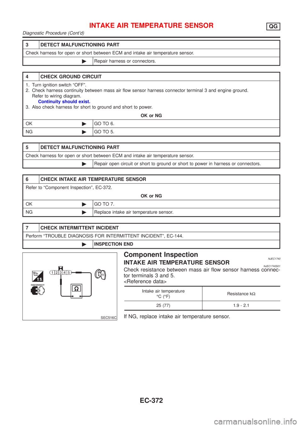
Component InspectionNJEC1740INTAKE AIR TEMPERATURE SENSORNJEC1740S01Check resistance between mass air flow sensor harness connec-
tor terminals 3 and 5.
Intake air temperature
ÉC (ÉF)Resistance kW
25 (77) 1.9 - 2.1
If NG, replace intake air temperature sensor.
INTAKE AIR TEMPERATURE SENSORQG
Diagnostic Procedure (Cont'd)
EC-372
Page 678 of 2493
3 DETECT MALFUNCTIONING PART
Check the following.
+Harness connectors F113, M169
+10A fuse
+Harness for open or short between heated oxygen sensor 1 (front) and fuse
©Repair harness or connectors.
4 CHECK GROUND CIRCUIT
1. Turn ignition switch ªOFFº.
2. Disconnect ECM harness connector.
3. Check harness continuity between heated oxygen sensor 1 (front) harness connector terminal 3 and ECM terminal 4.
Refer to wiring diagram.
Continuity should exist.
4. Also check harness for short to ground and short to power.
OK or NG
OK©GO TO 5.
NG©Repair open circuit or short to ground or short to power in harness or connectors.
5 CHECK HEATED OXYGEN SENSOR 1 HEATER (FRONT)
Refer to ªComponent Inspectionº, EC-382.
OK or NG
OK©GO TO 6.
NG©Replace heated oxygen sensor 1 (front).
6 CHECK INTERMITTENT INCIDENT
Perform ªTROUBLE DIAGNOSIS FOR INTERMITTENT INCIDENTº, EC-144.
©INSPECTION END
SEF935X
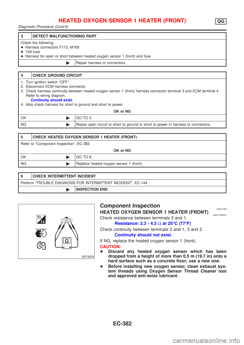
Component InspectionNJEC1230HEATED OXYGEN SENSOR 1 HEATER (FRONT)NJEC1230S01Check resistance between terminals 3 and 1.
Resistance: 2.3 - 4.3Wat 25ÉC (77ÉF)
Check continuity between terminals 2 and 1, 3 and 2.
Continuity should not exist.
If NG, replace the heated oxygen sensor 1 (front).
CAUTION:
+Discard any heated oxygen sensor which has been
dropped from a height of more than 0.5 m (19.7 in) onto a
hard surface such as a concrete floor; use a new one.
+Before installing new oxygen sensor, clean exhaust sys-
tem threads using Oxygen Sensor Thread Cleaner tool
and approved anti-seize lubricant.
HEATED OXYGEN SENSOR 1 HEATER (FRONT)QG
Diagnostic Procedure (Cont'd)
EC-382
Page 689 of 2493
SEF221W
Component InspectionNJEC1247HEATED OXYGEN SENSOR 2 HEATER (REAR)NJEC1247S01Check the following.
1. Check resistance between terminals 1 and 4.
Resistance: 2.3 - 4.3Wat 25ÉC (77ÉF)
2. Check continuity.
Terminal No. Continuity
1 and 2, 3, 4
No
4 and 1, 2, 3
If NG, replace the heated oxygen sensor 2 (rear).
CAUTION:
+Discard any heated oxygen sensor which has been
dropped from a height of more than 0.5 m (19.7 in) onto a
hard surface such as a concrete floor; use a new one.
+Before installing new oxygen sensor, clean exhaust sys-
tem threads using Oxygen Sensor Thread Cleaner tool
and approved anti-seize lubricant.
HEATED OXYGEN SENSOR 2 HEATER (REAR)QG
Component Inspection
EC-393
Page 695 of 2493
SEF121X
Component InspectionNJEC1745CRANKSHAFT POSITION SENSOR (POS)NJEC1745S011. Disconnect crankshaft position sensor (POS) harness connec-
tor.
2. Loosen the fixing bolt of the sensor.
3. Remove the sensor.
4. Visually check the sensor for chipping.
SEF122X
5. Check resistance as shown in the figure.
Terminal No. (Polarity) ResistanceW[at 25ÉC (77ÉF)]
3 (+) - 1 (±)
Except 0 or¥ 2 (+) - 1 (±)
3 (+) - 2 (±)
If NG, replace crankshaft position sensor.
CRANKSHAFT POSITION SENSOR (POS)QG
Component Inspection
EC-399
Page 697 of 2493
SEF552W
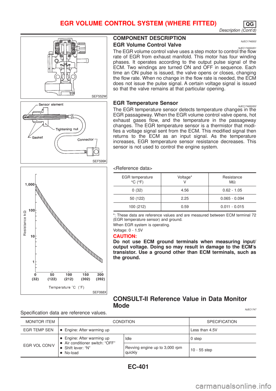
COMPONENT DESCRIPTIONNJEC1746S02EGR Volume Control ValveNJEC1746S0201The EGR volume control valve uses a step motor to control the flow
rate of EGR from exhaust manifold. This motor has four winding
phases. It operates according to the output pulse signal of the
ECM. Two windings are turned ON and OFF in sequence. Each
time an ON pulse is issued, the valve opens or closes, changing
the flow rate. When no change in the flow rate is needed, the ECM
does not issue the pulse signal. A certain voltage signal is issued
so that the valve remains at that particular opening.
SEF599K
EGR Temperature SensorNJEC1746S0202The EGR temperature sensor detects temperature changes in the
EGR passageway. When the EGR volume control valve opens, hot
exhaust gases flow, and the temperature in the passageway
changes. The EGR temperature sensor is a thermistor that modi-
fies a voltage signal sent from the ECM. This modified signal then
returns to the ECM as an input signal. As the temperature
increases, EGR temperature sensor resistance decreases. This
sensor is not used to control the engine system.
SEF068X
EGR temperature
ÉC (ÉF)Voltage*
VResistance
MW
0 (32) 4.56 0.62 - 1.05
50 (122) 2.25 0.065 - 0.094
100 (212) 0.59 0.011 - 0.015
*: These data are reference values and are measured between ECM terminal 72
(EGR temperature sensor) and ground.
When EGR system is operating.
Voltage: 0 - 1.5V
CAUTION:
Do not use ECM ground terminals when measuring input/
output voltage. Doing so may result in damage to the ECM's
transistor. Use a ground other than ECM terminals, such as
the ground.
CONSULT-II Reference Value in Data Monitor
Mode
NJEC1747Specification data are reference values.
MONITOR ITEM CONDITION SPECIFICATION
EGR TEMP SEN+Engine: After warming up Less than 4.5V
EGR VOL CON/V+Engine: After warming up
+Air conditioner switch: ªOFFº
+Shift lever: ªNº
+No-loadIdle 0 step
Revving engine up to 3,000 rpm
quickly10 - 55 step
EGR VOLUME CONTROL SYSTEM (WHERE FITTED)QG
Description (Cont'd)
EC-401
Page 705 of 2493
SEF069X
SEF605Y
SEF015Y
SEF560W
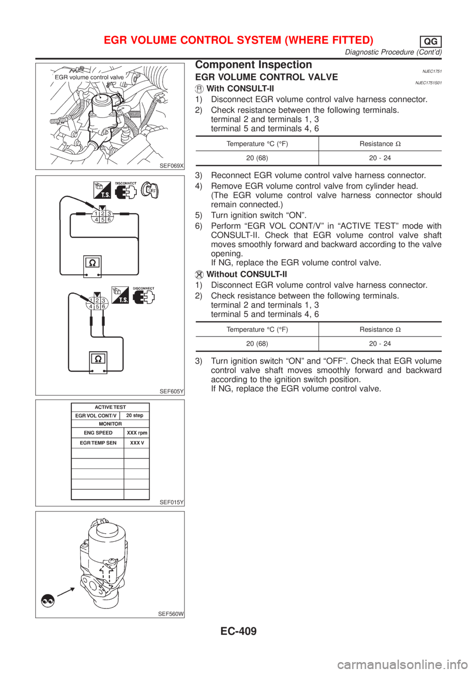
Component InspectionNJEC1751EGR VOLUME CONTROL VALVENJEC1751S01With CONSULT-II
1) Disconnect EGR volume control valve harness connector.
2) Check resistance between the following terminals.
terminal 2 and terminals 1, 3
terminal 5 and terminals 4, 6
Temperature ÉC (ÉF) ResistanceW
20 (68) 20 - 24
3) Reconnect EGR volume control valve harness connector.
4) Remove EGR volume control valve from cylinder head.
(The EGR volume control valve harness connector should
remain connected.)
5) Turn ignition switch ªONº.
6) Perform ªEGR VOL CONT/Vº in ªACTIVE TESTº mode with
CONSULT-II. Check that EGR volume control valve shaft
moves smoothly forward and backward according to the valve
opening.
If NG, replace the EGR volume control valve.
Without CONSULT-II
1) Disconnect EGR volume control valve harness connector.
2) Check resistance between the following terminals.
terminal 2 and terminals 1, 3
terminal 5 and terminals 4, 6
Temperature ÉC (ÉF) ResistanceW
20 (68) 20 - 24
3) Turn ignition switch ªONº and ªOFFº. Check that EGR volume
control valve shaft moves smoothly forward and backward
according to the ignition switch position.
If NG, replace the EGR volume control valve.
EGR VOLUME CONTROL SYSTEM (WHERE FITTED)QG
Diagnostic Procedure (Cont'd)
EC-409
Page 706 of 2493
SEF611Y
SEF068X
EGR TEMPERATURE SENSORNJEC1751S02Check resistance change and resistance value.
EGR temperature
ÉC (ÉF)Voltage
VResistance
MW
0 (32) 4.56 0.62 - 1.05
50 (122) 2.25 0.065 - 0.094
100 (212) 0.59 0.011 - 0.015
If NG, replace EGR temperature sensor.
EGR VOLUME CONTROL SYSTEM (WHERE FITTED)QG
Component Inspection (Cont'd)
EC-410
Page 711 of 2493
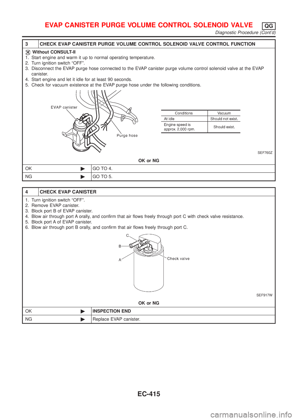
3 CHECK EVAP CANISTER PURGE VOLUME CONTROL SOLENOID VALVE CONTROL FUNCTION
Without CONSULT-II
1. Start engine and warm it up to normal operating temperature.
2. Turn ignition switch ªOFFº.
3. Disconnect the EVAP purge hose connected to the EVAP canister purge volume control solenoid valve at the EVAP
canister.
4. Start engine and let it idle for at least 90 seconds.
5. Check for vacuum existence at the EVAP purge hose under the following conditions.
SEF760Z
OK or NG
OK©GO TO 4.
NG©GO TO 5.
4 CHECK EVAP CANISTER
1. Turn ignition switch ªOFFº.
2. Remove EVAP canister.
3. Block port B of EVAP canister.
4. Blow air through port A orally, and confirm that air flows freely through port C with check valve resistance.
5. Block port A of EVAP canister.
6. Blow air through port B orally, and confirm that air flows freely through port C.
SEF917W
OK or NG
OK©INSPECTION END
NG©Replace EVAP canister.
EVAP CANISTER PURGE VOLUME CONTROL SOLENOID VALVEQG
Diagnostic Procedure (Cont'd)
EC-415