Page 872 of 2493
4 CHECK ENGINE COOLANT TEMPERATURE SENSOR
1. Remove engine coolant temperature sensor from the engine.
2. Check resistance between ECTS terminals 1 and 2 as shown in the figure.
SEF304X
OK or NG
OK©GO TO 5.
NG©Replace engine coolant temperature sensor.
5 CHECK INTERMITTENT INCIDENT
Refer to ªTROUBLE DIAGNOSIS FOR INTERMITTENT INCIDENTº, EC-559.
©INSPECTION END
DTC P0115 COOLANT TEMP SENYD
Diagnostic Procedure (Cont'd)
EC-576
Page 887 of 2493
3 CHECK CRANKSHAFT POSITION SENSOR (TDC)-I
1. Loosen the fixing bolt and remove the crankshaft position sensor (TDC).
2. Visually check the sensor for chipping.
SEF620S
OK or NG
OK©GO TO 4.
NG©Replace crankshaft position sensor (TDC).
4 CHECK CRANKSHAFT POSITION SENSOR (TDC)-II
1. Disconnect crankshaft position sensor (TDC) harness connector.
2. Check resistance between crankshaft position sensor (TDC) terminals 1 and 2.
SEF408Y
OK or NG
OK©GO TO 5.
NG©Replace crankshaft position sensor (TDC).
DTC P0335 CRANK POS SEN (TDC)YD
Diagnostic Procedure (Cont'd)
EC-591
Page 923 of 2493
10 CHECK ENGINE COOLANT TEMPERATURE SENSOR
1. Remove engine coolant temperature sensor.
2. Check resistance between engine coolant temperature sensor terminals 1 and 2 as shown in the figure.
SEF304X
OK or NG
OK©GO TO 11.
NG©Replace engine coolant temperature sensor.
11 CHECK MAIN 12 CAUSES
If the cause cannot be isolated, go to ªMAIN 12 CAUSES OF OVERHEATINGº, EC-633.
©INSPECTION END
PROCEDURE ANJEC0666S05
1 CHECK COOLING FAN POWER SUPPLY CIRCUIT
1. Turn ignition switch ªOFFº.
2. Disconnect cooling fan relay-1.
3. Turn ignition switch ªONº.
4. Check voltage between cooling fan relay-1 terminals 2, 3 and ground with CONSULT-II or tester.
SEF899Y
OK or NG
OK©GO TO 3.
NG©GO TO 2.
DTC P1217 OVER HEATYD
Diagnostic Procedure (Cont'd)
EC-627
Page 973 of 2493

DescriptionNJEC0760SYSTEM DESCRIPTIONNJEC0760S01
Sensor Input Signal to ECMECM
Func-
tionActuator
Crankshaft position sensor
(TDC)Engine speed
Glow
controlGlow lamp,
Glow relay
¯
Glow plugs Engine coolant tempera-
ture sensorEngine coolant tem-
perature
When engine coolant temperature is more than approximately
75ÉC (167ÉF), the glow relay turns off.
When coolant temperature is lower than approximately 75ÉC
(167ÉF):
+Ignition switch ON
After ignition switch has turned to ON, the glow relay turns ON
for a certain period of time in relation to engine coolant
temperature, allowing current to flow through glow plug.
+Cranking
The glow relay turns ON, allowing current to flow through glow
plug.
+Starting
After engine has started, current continues to flow through
glow plug (after-glow mode) for a certain period in relation to
engine coolant temperature.
The glow indicator lamp turns ON for a certain period of time in
relation to engine cooalnt temperature at the time glow relay is
turned ON.
SEF376Y
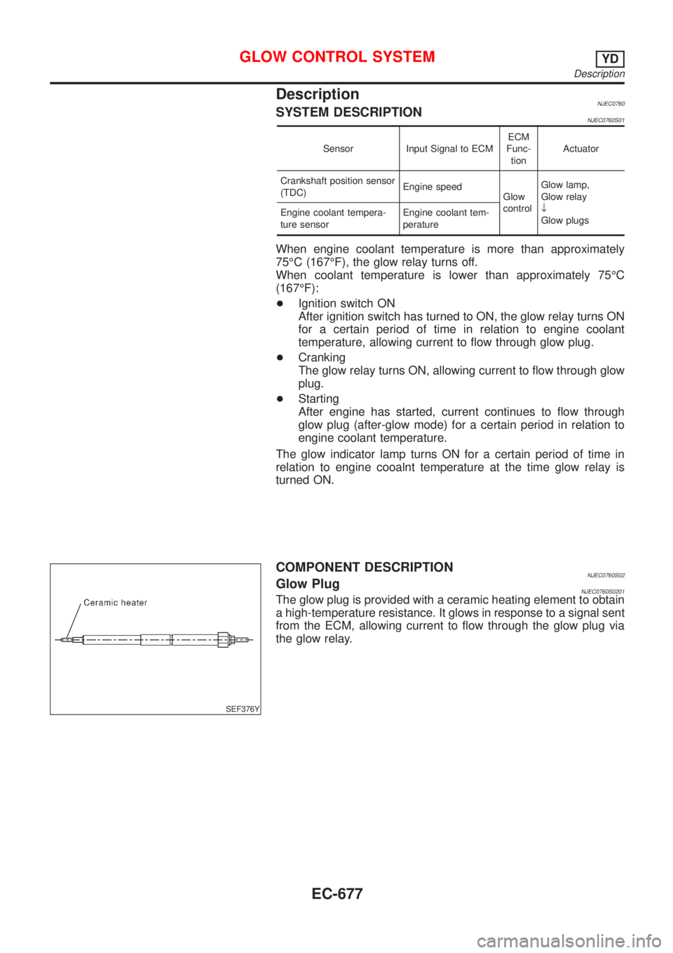
COMPONENT DESCRIPTIONNJEC0760S02Glow PlugNJEC0760S0201The glow plug is provided with a ceramic heating element to obtain
a high-temperature resistance. It glows in response to a signal sent
from the ECM, allowing current to flow through the glow plug via
the glow relay.
GLOW CONTROL SYSTEMYD
Description
EC-677
Page 980 of 2493

15 CHECK HARNESS CONTINUITY BETWEEN GLOW RELAY AND GLOW PLUG FOR OPEN AND SHORT
1. Disconnect glow plug harness connector.
2. Check harness continuity between glow relay terminal 3 and glow plug harness connector. Refer to Wiring Diagram.
Continuity should exist.
3. Also check harness for short to ground and short to power.
OK or NG
OK©GO TO 16.
NG©Repair open circuit or short to ground or short to power in harness or connectors.
16 CHECK GLOW RELAY
Check continuity between glow relay terminals 3 and 5 under the following conditions.
SEF433Y
OK or NG
OK©GO TO 17.
NG©Replace glow relay.
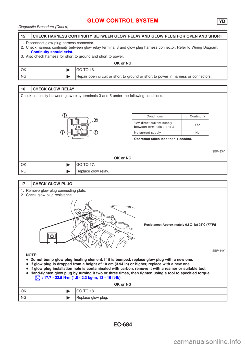
17 CHECK GLOW PLUG
1. Remove glow plug connecting plate.
2. Check glow plug resistance.
SEF434Y
NOTE:
+Do not bump glow plug heating element. If it is bumped, replace glow plug with a new one.
+If glow plug is dropped from a height of 10 cm (3.94 in) or higher, replace with a new one.
+If glow plug installation hole is contaminated with carbon, remove it with a reamer or suitable tool.
+Hand-tighten glow plug by turning it two or three times, then tighten using a tool to specified torque.
: 17.7 - 22.5 N´m (1.8 - 2.3 kg-m, 13 - 16 ft-lb)
OK or NG
OK©GO TO 18.
NG©Replace glow plug.
GLOW CONTROL SYSTEMYD
Diagnostic Procedure (Cont'd)
EC-684
Page 987 of 2493
7 CHECK EGR VOLUME CONTROL VALVE OUTPUT SIGNAL CIRCUIT FOR OPEN AND SHORT
1. Turn ignition switch ªOFFº.
2. Disconnect ECM harness connector.
3. Check harness continuity between ECM terminals and EGR volume control valve terminals as follows.
Refer to Wiring Diagram.
MTBL0463
Continuity should exist.
4. Also check harness for short to ground and short to power.
OK or NG
OK©GO TO 8.
NG©Repair open circuit or short to ground or short to power in harness or connectors.
8 CHECK EGR VOLUME CONTROL VALVE-I
Check resistance between EGR volume control valve terminal 2 and terminals 1, 3, terminal 5 and terminals 4, 6.
SEF414Y
OK or NG
OK (With CONSULT-II)©GO TO 9.
OK (Without CONSULT-
II)©GO TO 10.
NG©Replace EGR volume control valve.
EGR VOLUME CONTROL SYSTEMYD
Diagnostic Procedure (Cont'd)
EC-691
Page 998 of 2493
General SpecificationsNJEC0788Unit: rpm
Engine YD22DDT
Idle speed 725±25
Maximum engine speed 4,900
Injection NozzleNJEC0790Unit: kPa (bar, kg/cm2, psi)
Initial injection pressureNew 21,476 - 22,457 (214.7 - 224.5, 219 - 229, 3,114 - 3,256)
Limit 18,275 (182.7, 186, 2,650)
Engine Coolant Temperature SensorNJEC0791
Temperature ÉC (ÉF) Resistance kW
20 (68) 2.1 - 2.9
50 (122) 0.68 - 1.00
90 (194) 0.236 - 0.260
Crankshaft Position Sensor (TDC)NJEC0792
Resistance [at 20ÉC (68ÉF)]W495 - 605
Glow PlugNJEC0793
Resistance [at 25ÉC (77ÉF)]W0.8
Accelerator Position SensorNJEC0794
Throttle valve conditions Resistance between terminals 2 and 4 kW[at 25ÉC (77ÉF)]
Completely closed0.9 - 1.3
Partially open0.9 - 2.1
Completely open1.7 - 2.1
EGR Volume Control ValveNJEC0795
Resistance [at 25ÉC (77ÉF)]W13-17
SERVICE DATA AND SPECIFICATIONS (SDS)YD
General Specifications
EC-702
Page 1009 of 2493

SMA211A
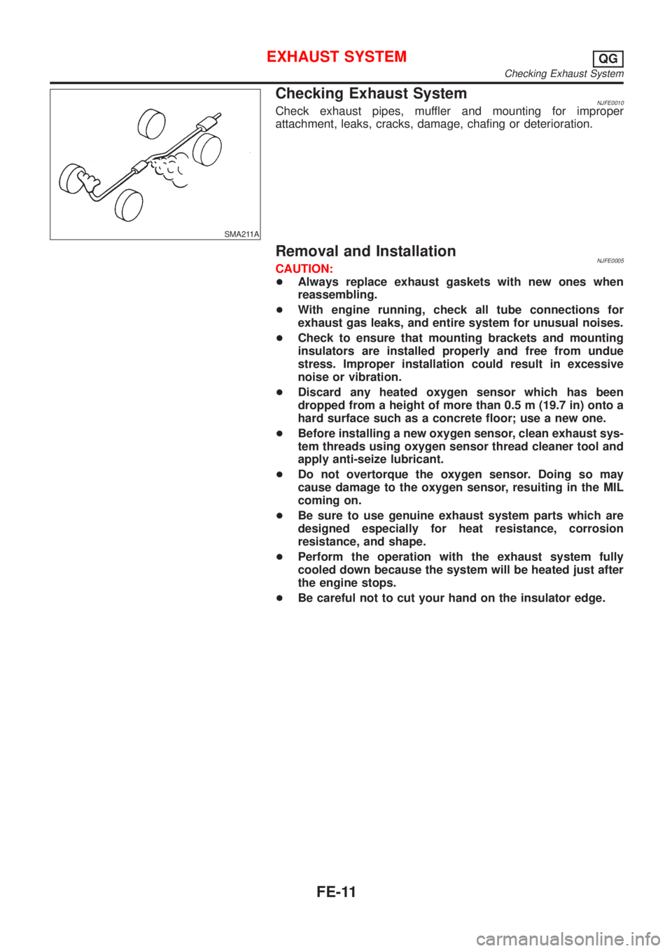
Checking Exhaust SystemNJFE0010Check exhaust pipes, muffler and mounting for improper
attachment, leaks, cracks, damage, chafing or deterioration.
Removal and InstallationNJFE0005CAUTION:
+Always replace exhaust gaskets with new ones when
reassembling.
+With engine running, check all tube connections for
exhaust gas leaks, and entire system for unusual noises.
+Check to ensure that mounting brackets and mounting
insulators are installed properly and free from undue
stress. Improper installation could result in excessive
noise or vibration.
+Discard any heated oxygen sensor which has been
dropped from a height of more than 0.5 m (19.7 in) onto a
hard surface such as a concrete floor; use a new one.
+Before installing a new oxygen sensor, clean exhaust sys-
tem threads using oxygen sensor thread cleaner tool and
apply anti-seize lubricant.
+Do not overtorque the oxygen sensor. Doing so may
cause damage to the oxygen sensor, resuiting in the MIL
coming on.
+Be sure to use genuine exhaust system parts which are
designed especially for heat resistance, corrosion
resistance, and shape.
+Perform the operation with the exhaust system fully
cooled down because the system will be heated just after
the engine stops.
+Be careful not to cut your hand on the insulator edge.
EXHAUST SYSTEMQG
Checking Exhaust System
FE-11