Page 1364 of 2493
2 CHECK POWER SOURCE CIRCUIT
1. Turn ignition switch to ªOFFº position.
2. Disconnect TCM harness connector.
3. Check resistance between terminal 4 and TCM harness connector terminal 2.
Resistance:
10-15W
SAT896JA
OK or NG
OK©GO TO 3.
NG©Check the following items:
+Dropping resistor
Refer to ªComponent Inspectionº, AT-180.
+Harness for short or open between TCM terminal 2 and terminal cord assembly (Main
harness)
LINE PRESSURE SOLENOID
VALVE
EXCEPT FOR EURO-OBD
Diagnostic Procedure (Cont'd)
AT-178
Page 1365 of 2493
3 CHECK POWER SOURCE CIRCUIT
1. Turn ignition switch to ªOFFº position.
2. Check resistance between terminal 4 and TCM harness connector terminal 1.
Resistance:
Approx. 0W
SAT897JA
If OK, check harness for short to ground and short to power.
3. Reinstall any part removed.
OK or NG
OK©GO TO 4.
NG©Repair open circuit or short to ground or short to power in harness or connectors.
4 CHECK DTC
Perform Self-diagnosis Code confirmation procedure, AT-175.
OK or NG
OK©INSPECTION END
NG©1. Perform TCM input/output signal inspection.
2. If NG, recheck TCM pin terminals for damage or loose connection with harness con-
nector.
LINE PRESSURE SOLENOID
VALVE
EXCEPT FOR EURO-OBD
Diagnostic Procedure (Cont'd)
AT-179
Page 1366 of 2493
SAT898JA
Component Inspection=NJAT0063LINE PRESSURE SOLENOID VALVENJAT0063S01+For removal, refer to AT-343.
Resistance CheckNJAT0063S0101+Check resistance between two terminals.
Solenoid valve Terminal No.Resistance
(Approx.)
Line pressure
solenoid valve4 Ground 2.5 - 5W
SAT899JA
Operation CheckNJAT0063S0102+Check solenoid valve by listening for its operating sound while
applying battery voltage to the terminal and ground.
SAT003K
DROPPING RESISTORNJAT0063S02+Check resistance between two terminals.
Resistance:
10-15W
LINE PRESSURE SOLENOID
VALVE
EXCEPT FOR EURO-OBD
Component Inspection
AT-180
Page 1378 of 2493
5 CHECK A/T FLUID TEMPERATURE SENSOR WITH TERMINAL CORD ASSEMBLY
1. Turn ignition switch to ªOFFº position.
2. Disconnect terminal cord assembly connector in engine compartment.
3. Check resistance between terminals 6 and 7 when A/T is cold.
Resistance:
Cold [20ÉC (68ÉF)]
Approximately 2.5 kW
SAT880JA
4. Reinstall any part removed.
OK or NG
OK (With CONSULT-II)©GO TO 2.
OK (Without CONSULT-
II)©GO TO 3.
NG©1. Remove oil pan.
2. Check the following items:
+A/T fluid temperature sensor
Refer to ªComponent Inspectionº, AT-192.
+Harness of terminal cord assembly for short or open
SAT298F
Component InspectionNJAT0271A/T FLUID TEMPERATURE SENSORNJAT0271S01+For removal, refer to AT-343.
+Check resistance between two terminals while changing tem-
perature as shown at left.
Temperature ÉC (ÉF) Resistance
20 (68) Approximately 2.5 kW
80 (176) Approximately 0.3 kW
DTC P0710 A/T FLUID TEMPERATURE SENSOR CIRCUITEURO-OBD
Diagnostic Procedure (Cont'd)
AT-192
Page 1393 of 2493

2 CHECK CONTROL VALVE
1. Disassemble control valve assembly. Refer to ªControl Valve Assemblyº, AT-375.
2. Check to ensure that:
+Valve, sleeve and plug slide along valve bore under their own weight.
+Valve, sleeve and plug are free from burrs, dents and scratches.
+Control valve springs are free from damage, deformation and fatigue.
+Hydraulic line is free from obstacles.
SAT367H
OK or NG
OK©GO TO 3.
NG©Repair control valve assembly.
3 CHECK DTC
Perform Diagnostic Trouble Code (DTC) confirmation procedure, AT-203.
OK or NG
OK©INSPECTION END
NG©Check control valve again. Repair or replace control valve assembly.
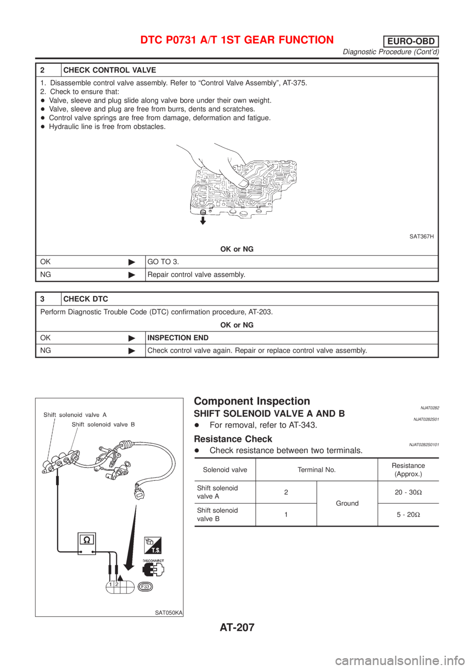
SAT050KA
Component InspectionNJAT0282SHIFT SOLENOID VALVE A AND BNJAT0282S01+For removal, refer to AT-343.
Resistance CheckNJAT0282S0101+Check resistance between two terminals.
Solenoid valve Terminal No.Resistance
(Approx.)
Shift solenoid
valve A2
Ground20-30W
Shift solenoid
valve B1 5-20W
DTC P0731 A/T 1ST GEAR FUNCTIONEURO-OBD
Diagnostic Procedure (Cont'd)
AT-207
Page 1400 of 2493
3 CHECK DTC
Perform Diagnostic Trouble Code (DTC) confirmation procedure, AT-210.
OK or NG
OK©INSPECTION END
NG©Check control valve again. Repair or replace control valve assembly.
SAT051KA
Component InspectionNJAT0286SHIFT SOLENOID VALVE BNJAT0286S01+For removal, refer to AT-343.
Resistance CheckNJAT0286S0101+Check resistance between two terminals.
Solenoid valve Terminal No.Resistance
(Approx.)
Shift solenoid
valve B1 Ground 5 - 20W
SAT884JB
Operation CheckNJAT0286S0102+Check solenoid valve by listening for its operating sound while
applying battery voltage to the terminal and ground.
DTC P0732 A/T 2ND GEAR FUNCTIONEURO-OBD
Diagnostic Procedure (Cont'd)
AT-214
Page 1406 of 2493
3 CHECK DTC
Perform Diagnostic Trouble Code (DTC) confirmation procedure, AT-216.
OK or NG
OK©INSPECTION END
NG©Check control valve again. Repair or replace control valve assembly.
SAT052KA
Component InspectionNJAT0290SHIFT SOLENOID VALVE ANJAT0290S01+For removal, refer to AT-343.
Resistance CheckNJAT0290S0101+Check resistance between two terminals.
Solenoid valve Terminal No.Resistance
(Approx.)
Shift solenoid
valve A2 Ground 20 - 30W
SAT886JB
Operation CheckNJAT0290S0102+Check solenoid valve by listening for its operating sound while
applying battery voltage to the terminal and ground.
DTC P0733 A/T 3RD GEAR FUNCTIONEURO-OBD
Diagnostic Procedure (Cont'd)
AT-220
Page 1416 of 2493
SAT848JB
Component Inspection=NJAT0294SOLENOID VALVESNJAT0294S01+For removal, refer to AT-343.
Resistance CheckNJAT0294S0101+Check resistance between two terminals.
Solenoid valve Terminal No.Resistance
(Approx.)
Shift solenoid
valve A2
Ground20-30W
Shift solenoid
valve B1 5-20W
Line pressure
solenoid valve4 2.5-5W
SAT847JB
Operation CheckNJAT0294S0102+Check solenoid valve by listening for its operating sound while
applying battery voltage to the terminal and ground.
DTC P0734 A/T 4TH GEAR FUNCTIONEURO-OBD
Component Inspection
AT-230