Page 1526 of 2493
A/T DEVICE CHECK=NJAT0105S011. Shift Lock SolenoidNJAT0105S0101+Check operation sound.
When ignition switch is turned to ªONº position and selector
lever is set in ªPº position.
Brake pedal Operation sound
Depressed Yes
Released No
SAT011K
2. Park Position SwitchNJAT0105S0102+Check resistance between A/T device harness terminal 2 and
3.
Condition Resistance
When selector lever is set in ªPº position and selector
lever button is released111W
When selector lever is not set in ªPº position and
selector lever button is released0W
SAT861JA
STOP LAMP SWITCHNJAT0105S02+Check continuity between terminals 1 and 2.
Condition Continuity
When brake pedal is depressed Yes
When brake pedal is released No
Check stop lamp switch after adjusting brake pedal Ð refer to
BR-12, ªBRAKE PEDAL AND BRACKETº.
A/T SHIFT LOCK SYSTEM
Diagnostic Procedure (Cont'd)
AT-340
Page 1565 of 2493
SAT115D
Oil StrainerNJAT0131S02+Check wire netting of oil strainer for damage.
SAT322GC
Shift Solenoid Valves A and B, Line Pressure Solenoid
Valve, Torque Converter Clutch Solenoid Valve and
Overrun Clutch Solenoid Valve
NJAT0131S03+Refer to ªResistance Checkº of each solenoid valve.
ValvesExcept for Euro-
OBDEuro-OBD
Shift solenoid valve A AT-145 AT-249
Shift solenoid vavle B AT-151 AT-255
Line pressure solenoid valve AT-180 AT-243
Torque converter clutch solenoid valve AT-162 AT-236
Overrun clutch solenoid valve AT-156 AT-270
SAT138D
Oil Cooler Relief Valve SpringNJAT0131S04+Check springs for damage or deformation.
+Measure free length and outer diameter.
Inspection standard:
Unit: mm (in)
Part No.!D
31872 31X00 17.0 (0.669) 8.0 (0.315)
SAT871J
ASSEMBLYNJAT01321. Install upper, inter and lower body.
a. Place oil circuit of upper body face up. Install steel balls in their
proper positions.
REPAIR FOR COMPONENT PARTS
Control Valve Assembly (Cont'd)
AT-379
Page 1644 of 2493

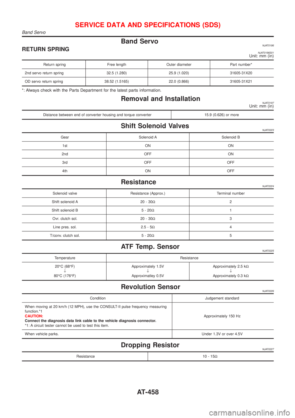
Band ServoNJAT0196RETURN SPRINGNJAT0196S01Unit: mm (in)
Return spring Free length Outer diameter Part number*
2nd servo return spring 32.5 (1.280) 25.9 (1.020) 31605-31X20
OD servo return spring 38.52 (1.5165) 22.0 (0.866) 31605-31X21
*: Always check with the Parts Department for the latest parts information.
Removal and InstallationNJAT0197Unit: mm (in)
Distance between end of converter housing and torque converter 15.9 (0.626) or more
Shift Solenoid ValvesNJAT0223
Gear Solenoid A Solenoid B
1st ON ON
2nd OFF ON
3rd OFF OFF
4th ON OFF
ResistanceNJAT0224
Solenoid valve Resistance (Approx.) Terminal number
Shift solenoid A 20 - 30W2
Shift solenoid B 5 - 20W1
Ovr. clutch sol. 20 - 30W3
Line pres. sol. 2.5 - 5W4
T/conv. clutch sol. 5 - 20W5
ATF Temp. SensorNJAT0225
Temperature Resistance
20ÉC (68ÉF)
¯
80ÉC (176ÉF)Approximately 1.5V
¯
Approximatley 0.5VApproximately 2.5 kW
¯
Approximately 0.3 kW
Revolution SensorNJAT0226
Condition Judgement standard
When moving at 20 km/h (12 MPH), use the CONSULT-II pulse frequency measuring
function.*1
CAUTION:
Connect the diagnosis data link cable to the vehicle diagnosis connector.
*1: A circuit tester cannot be used to test this item.Approximately 150 Hz
When vehicle parks.Under 1.3V or over 4.5V
Dropping ResistorNJAT0227
Resistance 10 - 15W
SERVICE DATA AND SPECIFICATIONS (SDS)
Band Servo
AT-458
Page 1647 of 2493

Noise, Vibration and Harshness (NVH)
Troubleshooting
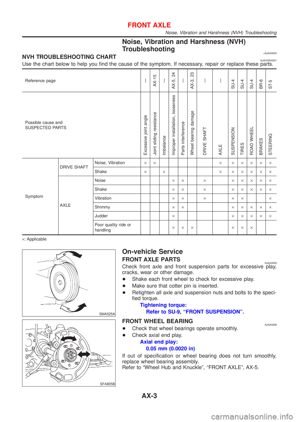
=NJAX0004NVH TROUBLESHOOTING CHARTNJAX0004S01Use the chart below to help you find the cause of the symptom. If necessary, repair or replace these parts.
Reference pageÐ
AX-15
Ð
AX-5, 24
Ð
AX-3, 23
Ð
Ð
SU-4
SU-4
SU-4
BR-6
ST-5
Possible cause and
SUSPECTED PARTS
Excessive joint angle
Joint sliding resistance
Imbalance
Improper installation, looseness
Parts interference
Wheel bearing damage
DRIVE SHAFT
AXLE
SUSPENSION
TIRES
ROAD WHEEL
BRAKES
STEERING
SymptomDRIVE SHAFTNoise, Vibration´´ ´ ´´´´´
Shake´ ´ ´ ´´´´´
AXLENoise´´ ´ ´´´´´
Shake´´ ´ ´´´´´
Vibration´´ ´ ´´ ´
Shimmy´´ ´´´´´
Judder´ ´´´´´
Poor quality ride or
handling´´´ ´´´
´: Applicable
SMA525A
On-vehicle Service
FRONT AXLE PARTSNJAX0005Check front axle and front suspension parts for excessive play,
cracks, wear or other damage.
+Shake each front wheel to check for excessive play.
+Make sure that cotter pin is inserted.
+Retighten all axle and suspension nuts and bolts to the speci-
fied torque.
Tightening torque:
Refer to SU-9, ªFRONT SUSPENSIONº.
SFA805B
FRONT WHEEL BEARINGNJAX0006+Check that wheel bearings operate smoothly.
+Check axial end play.
Axial end play:
0.05 mm (0.0020 in)
If out of specification or wheel bearing does not turn smoothly,
replace wheel bearing assembly.
Refer to ªWheel Hub and Knuckleº, ªFRONT AXLEº, AX-5.
FRONT AXLE
Noise, Vibration and Harshness (NVH) Troubleshooting
AX-3
Page 1721 of 2493
RemovalNJBR0123
SBR631E
1. Remove parts shown below.
+Air duct, air cleaner case (upper)
+Engine cover
+Rocker cover
+Exhaust manifold cover
+EGR tube
2. Disconnect vacuum hose from vacuum pump.
3. Remove cylinder head rear cover plate.
+Use a tool such as seal cutter (SST) to remove.
4. Loosen and remove rear cam sprocket installation bolts.
+Camshaft should not be attached. Using engine inner
resistance, loosen installation bolts.
SBR632E
5. Remove vacuum pump and cylinder head rear cover assem-
bly.
+Remove and install vacuum pump, sprocket, drive chain, and
chain guide as an assembly.
+Loosen mounting bolts in the reverse order of the numbers
shown in the figure to the left.
+Remove only bolts that are shown in the figure. (Be especially
careful not to remove M6 bolts on the vacuum pump.)
+Use a tool such as a seal cutter (SST).
VACUUM PUMP
Removal
BR-23
Page 1722 of 2493

SBR633E
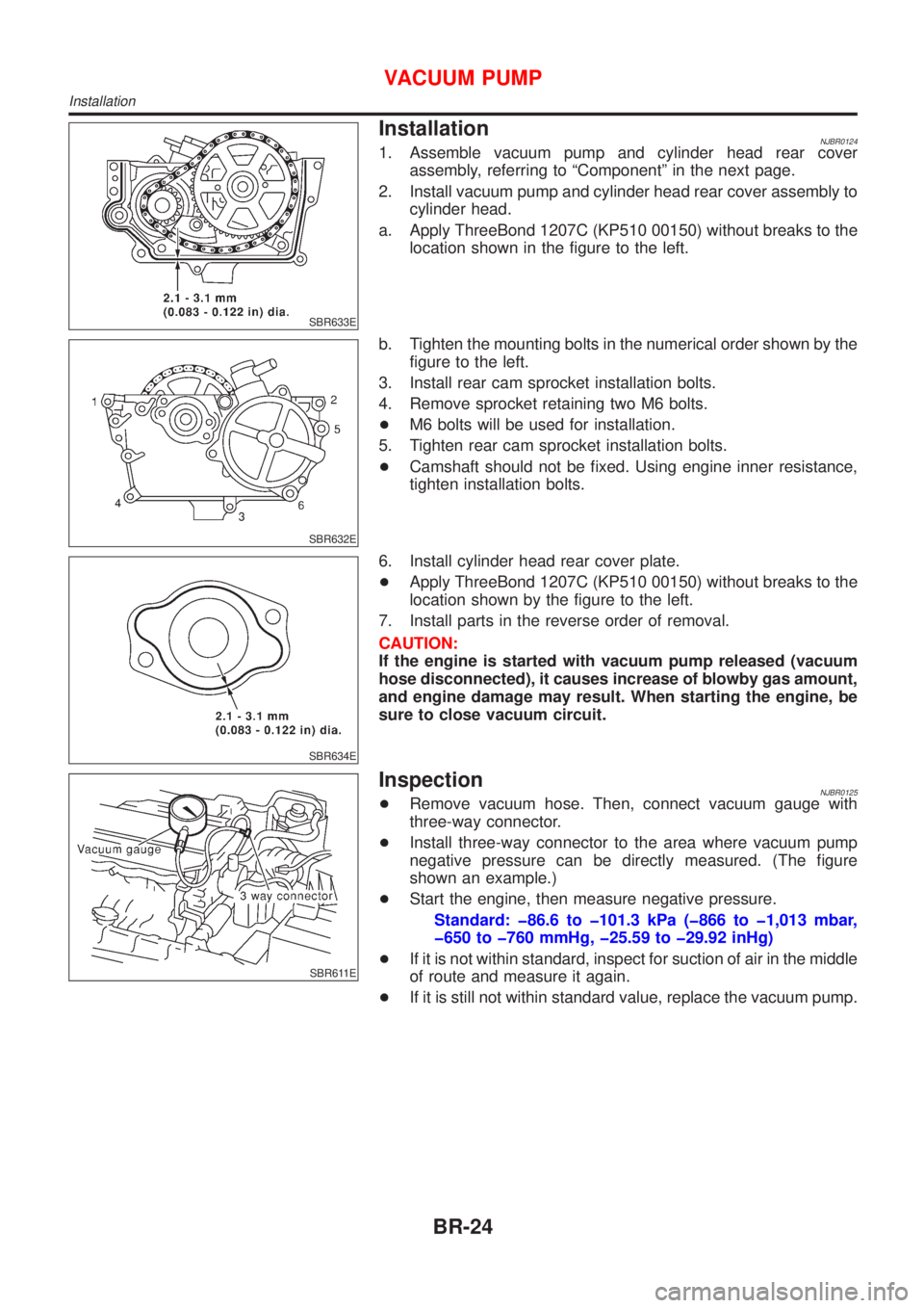
InstallationNJBR01241. Assemble vacuum pump and cylinder head rear cover
assembly, referring to ªComponentº in the next page.
2. Install vacuum pump and cylinder head rear cover assembly to
cylinder head.
a. Apply ThreeBond 1207C (KP510 00150) without breaks to the
location shown in the figure to the left.
SBR632E
b. Tighten the mounting bolts in the numerical order shown by the
figure to the left.
3. Install rear cam sprocket installation bolts.
4. Remove sprocket retaining two M6 bolts.
+M6 bolts will be used for installation.
5. Tighten rear cam sprocket installation bolts.
+Camshaft should not be fixed. Using engine inner resistance,
tighten installation bolts.
SBR634E
6. Install cylinder head rear cover plate.
+Apply ThreeBond 1207C (KP510 00150) without breaks to the
location shown by the figure to the left.
7. Install parts in the reverse order of removal.
CAUTION:
If the engine is started with vacuum pump released (vacuum
hose disconnected), it causes increase of blowby gas amount,
and engine damage may result. When starting the engine, be
sure to close vacuum circuit.
SBR611E
InspectionNJBR0125+Remove vacuum hose. Then, connect vacuum gauge with
three-way connector.
+Install three-way connector to the area where vacuum pump
negative pressure can be directly measured. (The figure
shown an example.)
+Start the engine, then measure negative pressure.
Standard: þ86.6 to þ101.3 kPa (þ866 to þ1,013 mbar,
þ650 to þ760 mmHg, þ25.59 to þ29.92 inHg)
+If it is not within standard, inspect for suction of air in the middle
of route and measure it again.
+If it is still not within standard value, replace the vacuum pump.
VACUUM PUMP
Installation
BR-24
Page 1767 of 2493
Wheel Sensor or RotorNJBR0098DIAGNOSTIC PROCEDURENJBR0098S01
1 INSPECTION START
Wheel sensor inspection
SBR476EB
©GO TO 2.
2 CHECK CONNECTOR
1. Disconnect connectors from control unit and wheel sensor according to the self-diagnostic results. Check terminals for
damage or loose connections. Then reconnect connectors.
2. Carry out self-diagnosis again.
Does warning lamp activate again?
Ye s©GO TO 3.
No©INSPECTION END
3 CHECK WHEEL SENSOR CIRCUIT
1. Disconnect control unit connector.
2. Check resistance between control unit connector terminals.
Code No. 21 or 22 (Front RH wheel)
Terminals 4 and 5
Code No. 25 or 26 (Front LH wheel)
Terminals 6 and 7
Code No. 31 or 32 (Rear RH wheel)
Terminals 1 and 3
Code No. 35 or 36 (Rear LH wheel)
Terminals 8 and 9
Resistance: 1.44 - 1.76 kW
SBR477EC
Is resistance 1.44 - 1.76 kW?
Ye s©GO TO 5.
No©GO TO 4.
TROUBLE DIAGNOSES FOR SELF-DIAGNOSTIC ITEMSABS
Wheel Sensor or Rotor
BR-69
Page 1768 of 2493
4 CHECK WHEEL SENSOR
Check resistance of each sensor. (See NOTE.)
Resistance: 1.44 - 1.76 kW
SBR478EC
Is resistance 1.44 - 1.76 kW?
Ye s©Repair harness and connectors between control unit connector and wheel sensor con-
nector.
No©Replace wheel sensor.
5 CHECK TIRE
Check for inflation pressure, wear and size of each tire.
Are tire pressure and size correct and is tire wear within specifications?
Ye s©GO TO 6.
No©Adjust tire pressure or replace tire(s).
TROUBLE DIAGNOSES FOR SELF-DIAGNOSTIC ITEMSABS
Wheel Sensor or Rotor (Cont'd)
BR-70