Page 1439 of 2493
Diagnostic ProcedureNJAT0309
1 CHECK VALVE RESISTANCE
1. Turn ignition switch to ªOFFº position.
2. Disconnect terminal cord assembly connector in engine compartment.
3. Check resistance between terminal 1 and ground.
Resistance:
5-20W
SAT904JB
OK or NG
OK©GO TO 2.
NG©1. Remove control valve assembly. Refer to AT-343.
2. Check the following items:
+Shift solenoid valve B
Refer to ªComponent Inspectionº, AT-255.
+Harness of terminal cord assembly for short or open
DTC P0755 SHIFT SOLENOID VALVE BEURO-OBD
Diagnostic Procedure
AT-253
Page 1441 of 2493
SAT057KA
Component InspectionNJAT0310SHIFT SOLENOID VALVE BNJAT0310S01+For removal, refer to AT-343.
Resistance CheckNJAT0310S0101+Check resistance between two terminals.
Solenoid valve Terminal No.Resistance
(Approx.)
Shift solenoid
valve B1 Ground 5 - 20W
SAT907JB
Operation CheckNJAT0310S0102+Check solenoid valve by listening for its operating sound while
applying battery voltage to the terminal and ground.
DTC P0755 SHIFT SOLENOID VALVE BEURO-OBD
Component Inspection
AT-255
Page 1454 of 2493
Diagnostic ProcedureNJAT0317
1 CHECK VALVE RESISTANCE
1. Turn ignition switch to ªOFFº position.
2. Disconnect terminal cord assembly connector in engine compartment.
3. Check resistance between terminal 3 and ground.
Resistance:
20-30W
SAT908JB
OK or NG
OK©GO TO 2.
NG©1. Remove control valve assembly. Refer to AT-343.
2. Check the following items:
+Overrun clutch solenoid valve
Refer to ªComponent Inspectionº, AT-270.
+Harness of terminal cord assembly for short or open
DTC P1760 OVERRUN CLUTCH SOLENOID VALVEEURO-OBD
Diagnostic Procedure
AT-268
Page 1456 of 2493
SAT910JB
Component InspectionNJAT0318OVERRUN CLUTCH SOLENOID VALVENJAT0318S01+For removal, refer to AT-343.
Resistance CheckNJAT0318S0101+Check resistance between two terminals.
Solenoid valve Terminal No.Resistance
(Approx.)
Overrun clutch
solenoid valve3 Ground 20 - 30W
SAT911JB
Operation CheckNJAT0318S0102+Check solenoid valve by listening for its operating sound while
applying battery voltage to the terminal and ground.
DTC P1760 OVERRUN CLUTCH SOLENOID VALVEEURO-OBD
Component Inspection
AT-270
Page 1461 of 2493

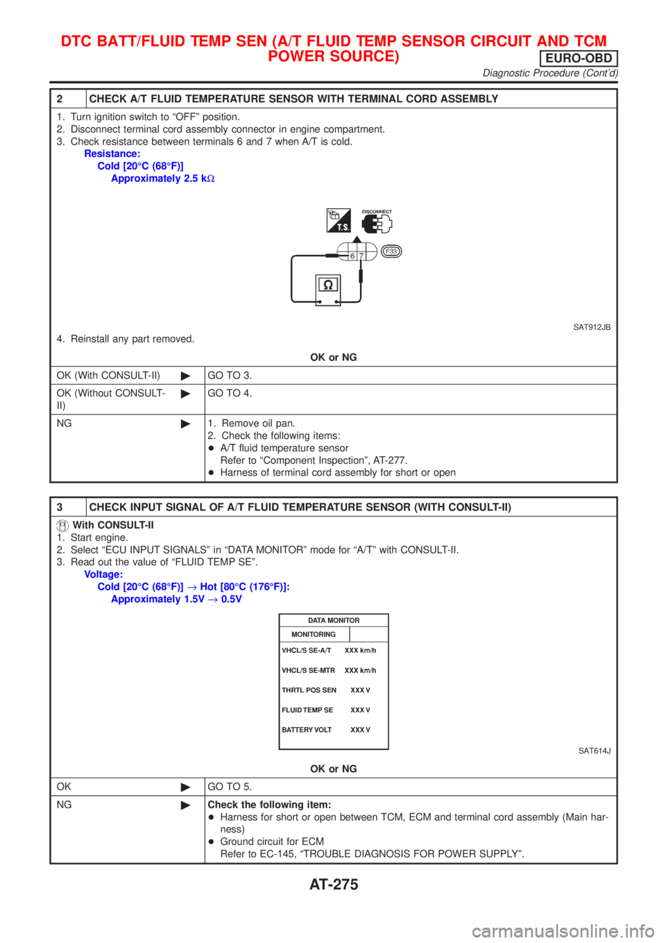
2 CHECK A/T FLUID TEMPERATURE SENSOR WITH TERMINAL CORD ASSEMBLY
1. Turn ignition switch to ªOFFº position.
2. Disconnect terminal cord assembly connector in engine compartment.
3. Check resistance between terminals 6 and 7 when A/T is cold.
Resistance:
Cold [20ÉC (68ÉF)]
Approximately 2.5 kW
SAT912JB
4. Reinstall any part removed.
OK or NG
OK (With CONSULT-II)©GO TO 3.
OK (Without CONSULT-
II)©GO TO 4.
NG©1. Remove oil pan.
2. Check the following items:
+A/T fluid temperature sensor
Refer to ªComponent Inspectionº, AT-277.
+Harness of terminal cord assembly for short or open
3 CHECK INPUT SIGNAL OF A/T FLUID TEMPERATURE SENSOR (WITH CONSULT-II)
With CONSULT-II
1. Start engine.
2. Select ªECU INPUT SIGNALSº in ªDATA MONITORº mode for ªA/Tº with CONSULT-II.
3. Read out the value of ªFLUID TEMP SEº.
Voltage:
Cold [20ÉC (68ÉF)]®Hot [80ÉC (176ÉF)]:
Approximately 1.5V®0.5V
SAT614J
OK or NG
OK©GO TO 5.
NG©Check the following item:
+Harness for short or open between TCM, ECM and terminal cord assembly (Main har-
ness)
+Ground circuit for ECM
Refer to EC-145, ªTROUBLE DIAGNOSIS FOR POWER SUPPLYº.
DTC BATT/FLUID TEMP SEN (A/T FLUID TEMP SENSOR CIRCUIT AND TCM
POWER SOURCE)
EURO-OBD
Diagnostic Procedure (Cont'd)
AT-275
Page 1462 of 2493

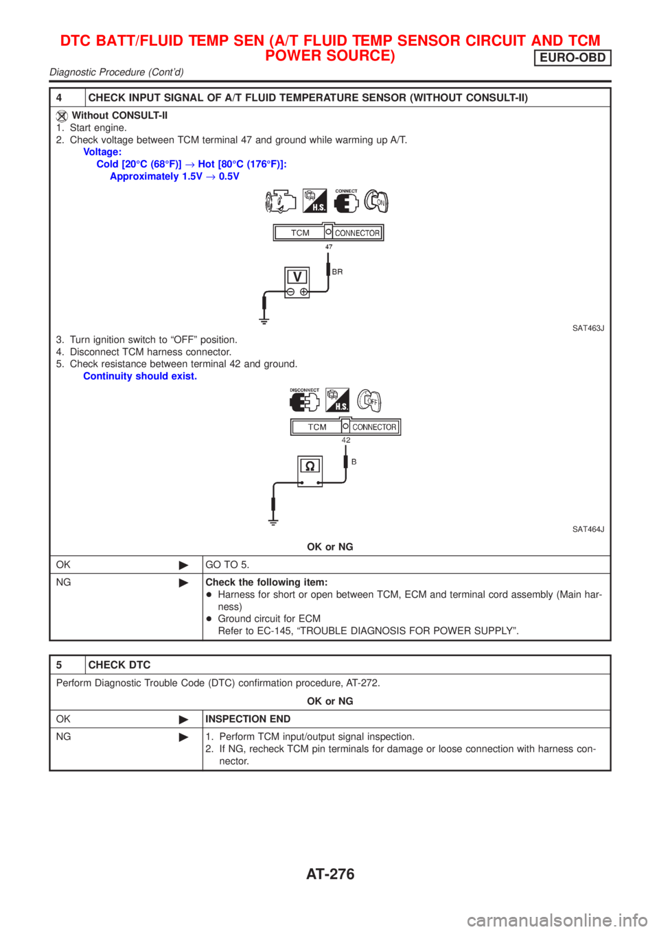
4 CHECK INPUT SIGNAL OF A/T FLUID TEMPERATURE SENSOR (WITHOUT CONSULT-II)
Without CONSULT-II
1. Start engine.
2. Check voltage between TCM terminal 47 and ground while warming up A/T.
Voltage:
Cold [20ÉC (68ÉF)]®Hot [80ÉC (176ÉF)]:
Approximately 1.5V®0.5V
SAT463J
3. Turn ignition switch to ªOFFº position.
4. Disconnect TCM harness connector.
5. Check resistance between terminal 42 and ground.
Continuity should exist.
SAT464J
OK or NG
OK©GO TO 5.
NG©Check the following item:
+Harness for short or open between TCM, ECM and terminal cord assembly (Main har-
ness)
+Ground circuit for ECM
Refer to EC-145, ªTROUBLE DIAGNOSIS FOR POWER SUPPLYº.
5 CHECK DTC
Perform Diagnostic Trouble Code (DTC) confirmation procedure, AT-272.
OK or NG
OK©INSPECTION END
NG©1. Perform TCM input/output signal inspection.
2. If NG, recheck TCM pin terminals for damage or loose connection with harness con-
nector.
DTC BATT/FLUID TEMP SEN (A/T FLUID TEMP SENSOR CIRCUIT AND TCM
POWER SOURCE)
EURO-OBD
Diagnostic Procedure (Cont'd)
AT-276
Page 1463 of 2493
SAT298F
Component InspectionNJAT0322A/T FLUID TEMPERATURE SENSORNJAT0322S01+For removal, refer to AT-343.
+Check resistance between two terminals while changing tem-
perature as shown at left.
Temperature ÉC (ÉF) Resistance
20 (68) Approximately 2.5 kW
80 (176) Approximately 0.3 kW
DTC BATT/FLUID TEMP SEN (A/T FLUID TEMP SENSOR CIRCUIT AND TCM
POWER SOURCE)
EURO-OBD
Component Inspection
AT-277
Page 1475 of 2493

2 CHECK TCM GROUND CIRCUIT
1. Turn ignition switch to ªOFFº position.
2. Disconnect TCM harness connector.
3. Check continuity between TCM terminals 25, 48 and ground.
SAT468J
Continuity should exist.
If OK, check harness for short to ground and short to power.
OK or NG
OK©GO TO 3.
NG©Repair open circuit or short to ground or short to power in harness or connectors. Refer
to ªWiring Diagram Ð AT Ð MAINº, AT-121.
3 CHECK LAMP CIRCUIT
1. Turn ignition switch to ªOFFº position.
2. Check resistance between TCM terminals 13 and 10.
Resistance: 50 - 100W
SAT469JB
3. Reinstall any part removed.
OK or NG
OK©GO TO 4.
NG©Check the following items:
+O/D OFF indicator lamp.
Refer to EL-89, ªMETERS AND GAUGESº.
+Harness and fuse for short or open between ignition switch and O/D OFF indicator
lamp (Main harness)
Refer to EL-10, ªPOWER SUPPLY ROUTINGº.
+Harness for short or open between O/D OFF indicator lamp and TCM.
TROUBLE DIAGNOSES FOR SYMPTOMS
1. O/D OFF Indicator Lamp Does Not Come On (Cont'd)
AT-289