Page 2032 of 2493
NHA386
ELECTRICAL COMPONENTS INSPECTION=NJHA0146Fan SwitchNJHA0146S01Check continuity between terminals at each switch position.
KNOB POSITION Continuity between terminals
OFF No continuity
1 13Ð14Ð18
2 13Ð15Ð18
3 13Ð16Ð18
4 13Ð17Ð18
Blower MotorNJHA0146S02Confirm smooth rotation of the blower motor.
+Ensure that there are no foreign particles inside the intake unit.
RHA706H
Blower ResistorNJHA0146S03Check resistance between terminals.
Terminal No. Resistance
(+) (þ)Models with max
hot doorModels without
max hot door
4
1Approx. 2.4 - 2.8W
3Approx. 0.58 -
0.7WApprox. 1.2 - 1.4W
2Approx. 0.22 -
0.26WApprox. 0.43 -
0.51W
TROUBLE DIAGNOSES
Blower Motor (Cont'd)
HA-60
Page 2095 of 2493
SEL909TA
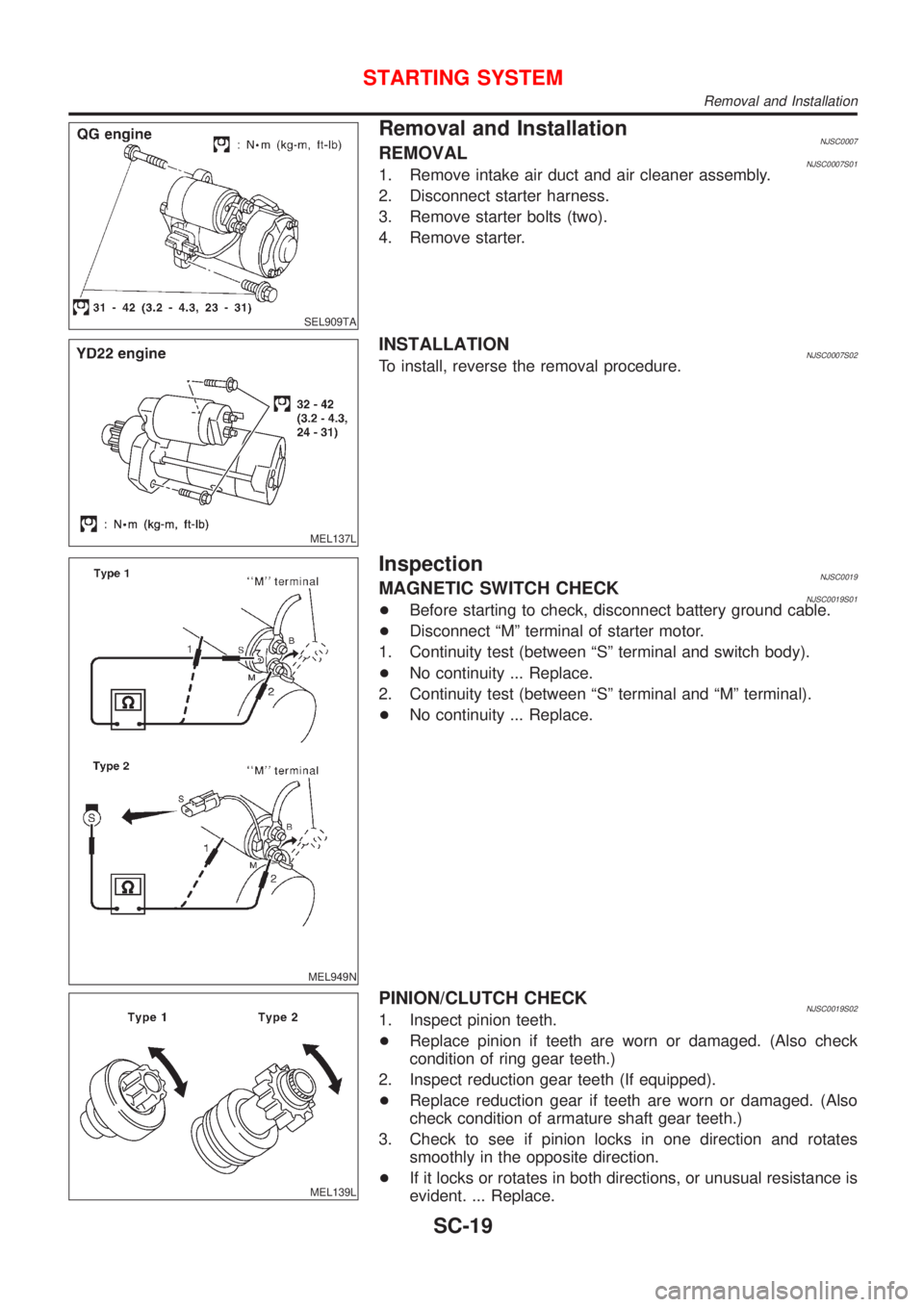
Removal and InstallationNJSC0007REMOVALNJSC0007S011. Remove intake air duct and air cleaner assembly.
2. Disconnect starter harness.
3. Remove starter bolts (two).
4. Remove starter.
MEL137L
INSTALLATIONNJSC0007S02To install, reverse the removal procedure.
MEL949N
InspectionNJSC0019MAGNETIC SWITCH CHECKNJSC0019S01+Before starting to check, disconnect battery ground cable.
+Disconnect ªMº terminal of starter motor.
1. Continuity test (between ªSº terminal and switch body).
+No continuity ... Replace.
2. Continuity test (between ªSº terminal and ªMº terminal).
+No continuity ... Replace.
MEL139L
PINION/CLUTCH CHECKNJSC0019S021. Inspect pinion teeth.
+Replace pinion if teeth are worn or damaged. (Also check
condition of ring gear teeth.)
2. Inspect reduction gear teeth (If equipped).
+Replace reduction gear if teeth are worn or damaged. (Also
check condition of armature shaft gear teeth.)
3. Check to see if pinion locks in one direction and rotates
smoothly in the opposite direction.
+If it locks or rotates in both directions, or unusual resistance is
evident. ... Replace.
STARTING SYSTEM
Removal and Installation
SC-19
Page 2107 of 2493
INSTALLATIONNJSC0013S02To install, reverse the removal procedure.
SEL032Z
DisassemblyNJSC0021REAR COVERNJSC0021S01CAUTION:
Rear cover may be hard to remove because a ring is used to
lock outer race of rear bearing. To facilitate removal of rear
cover, heat just bearing box section with a 200W soldering
iron.
Do not use a heat gun, as it can damage diode assembly.
REAR BEARINGNJSC0021S02CAUTION:
+Do not reuse rear bearing after removal. Replace with a
new one.
+Do not lubricate rear bearing outer race.
SEL033Z
InspectionNJSC0022ROTOR CHECKNJSC0022S011. Resistance test
Resistance: Refer to SDS (SC-35).
+Not within the specified values ... Replace rotor.
2. Insulator test
+Continuity exists ... Replace rotor.
3. Check slip ring for wear.
Slip ring minimum outer diameter:
Refer to SDS (SC-35).
+Not within the specified values ... Replace rotor.
CHARGING SYSTEM
Removal and Installation (Cont'd)
SC-31
Page 2111 of 2493
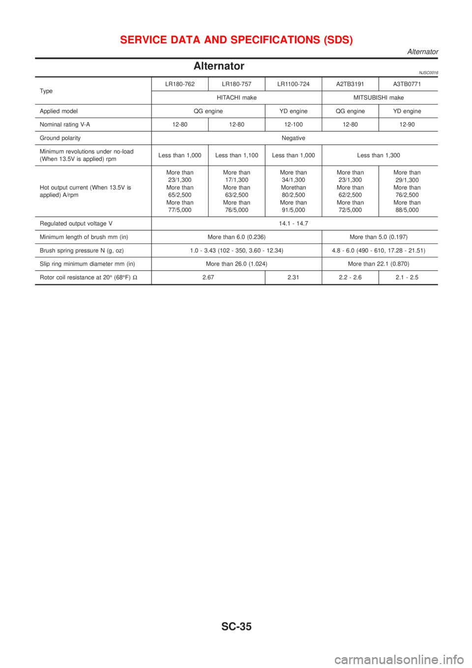
AlternatorNJSC0016
TypeLR180-762 LR180-757 LR1100-724 A2TB3191 A3TB0771
HITACHI make MITSUBISHI make
Applied model QG engine YD engine QG engine YD engine
Nominal rating V-A 12-80 12-80 12-100 12-80 12-90
Ground polarityNegative
Minimum revolutions under no-load
(When 13.5V is applied) rpmLess than 1,000 Less than 1,100 Less than 1,000 Less than 1,300
Hot output current (When 13.5V is
applied) A/rpmMore than
23/1,300
More than
65/2,500
More than
77/5,000More than
17/1,300
More than
63/2,500
More than
76/5,000More than
34/1,300
Morethan
80/2,500
More than
91/5,000More than
23/1,300
More than
62/2,500
More than
72/5,000More than
29/1,300
More than
76/2,500
More than
88/5,000
Regulated output voltage V 14.1 - 14.7
Minimum length of brush mm (in) More than 6.0 (0.236) More than 5.0 (0.197)
Brush spring pressure N (g, oz) 1.0 - 3.43 (102 - 350, 3.60 - 12.34) 4.8 - 6.0 (490 - 610, 17.28 - 21.51)
Slip ring minimum diameter mm (in) More than 26.0 (1.024) More than 22.1 (0.870)
Rotor coil resistance at 20É (68ÉF)W2.67 2.31 2.2 - 2.6 2.1 - 2.5
SERVICE DATA AND SPECIFICATIONS (SDS)
Alternator
SC-35
Page 2134 of 2493
CEL083
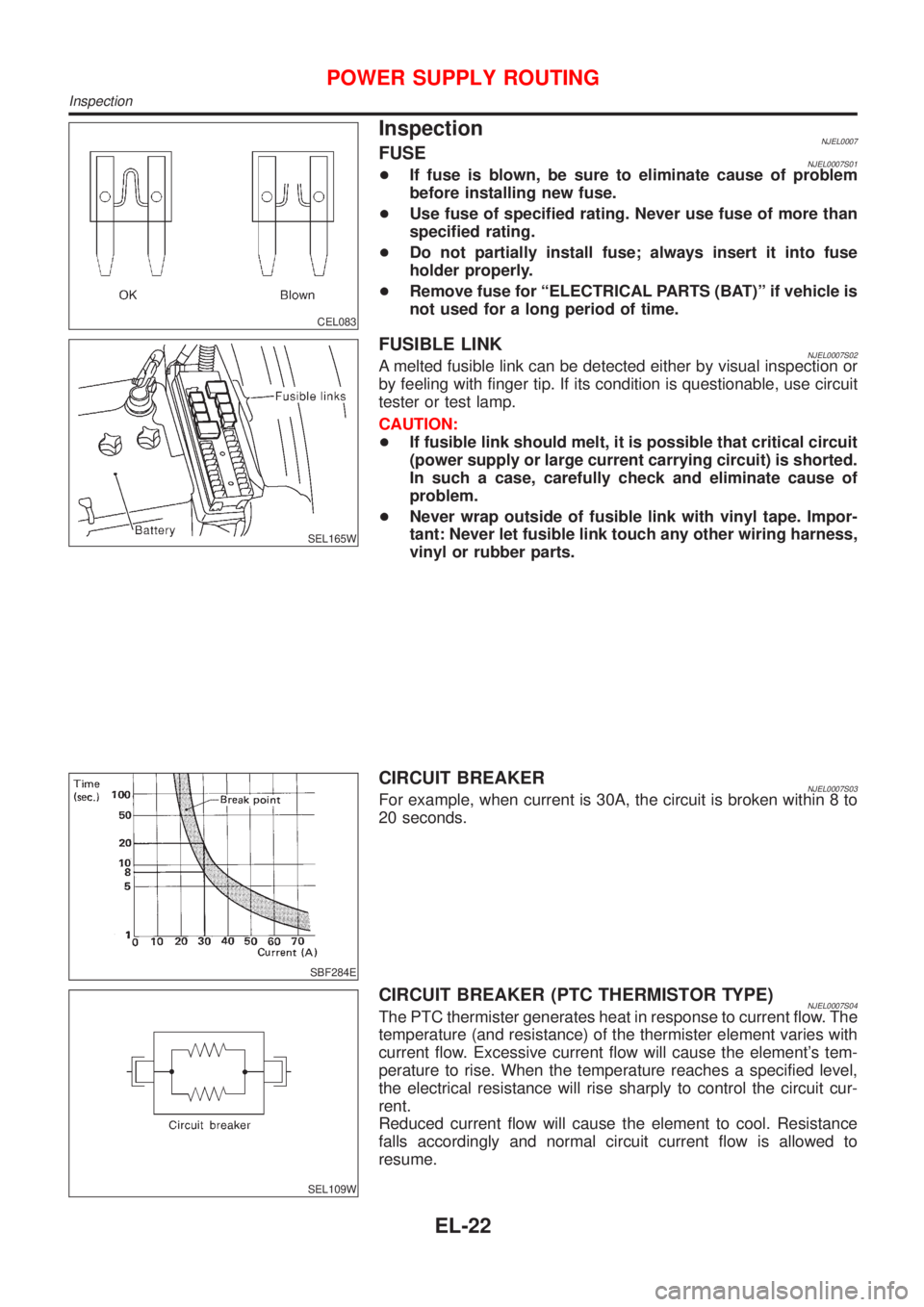
InspectionNJEL0007FUSENJEL0007S01+If fuse is blown, be sure to eliminate cause of problem
before installing new fuse.
+Use fuse of specified rating. Never use fuse of more than
specified rating.
+Do not partially install fuse; always insert it into fuse
holder properly.
+Remove fuse for ªELECTRICAL PARTS (BAT)º if vehicle is
not used for a long period of time.
SEL165W
FUSIBLE LINKNJEL0007S02A melted fusible link can be detected either by visual inspection or
by feeling with finger tip. If its condition is questionable, use circuit
tester or test lamp.
CAUTION:
+If fusible link should melt, it is possible that critical circuit
(power supply or large current carrying circuit) is shorted.
In such a case, carefully check and eliminate cause of
problem.
+Never wrap outside of fusible link with vinyl tape. Impor-
tant: Never let fusible link touch any other wiring harness,
vinyl or rubber parts.
SBF284E
CIRCUIT BREAKERNJEL0007S03For example, when current is 30A, the circuit is broken within 8 to
20 seconds.
SEL109W
CIRCUIT BREAKER (PTC THERMISTOR TYPE)NJEL0007S04The PTC thermister generates heat in response to current flow. The
temperature (and resistance) of the thermister element varies with
current flow. Excessive current flow will cause the element's tem-
perature to rise. When the temperature reaches a specified level,
the electrical resistance will rise sharply to control the circuit cur-
rent.
Reduced current flow will cause the element to cool. Resistance
falls accordingly and normal circuit current flow is allowed to
resume.
POWER SUPPLY ROUTING
Inspection
EL-22
Page 2202 of 2493
WATER TEMPERATURE GAUGENJEL0442S04The water temperature gauge indicates the engine coolant temperature. The reading on the gauge is based
on the resistance of the thermal transmitter.
As the temperature of the coolant increases, the resistance of the thermal transmitter decreases. A variable
ground is supplied to terminal 20 of the combination meter for the water temperature gauge. The needle on
the gauge moves from ªCº to ªHº.
TACHOMETERNJEL0442S05The tachometer indicates engine speed in revolutions per minute (rpm).
The tachometer is regulated by a signal
+from terminal 32 (Gasoline engine models) or 439 (Diesel engine models) of the ECM
+to combination meter terminal 22 for the tachometer.
FUEL GAUGENJEL0442S06The fuel gauge indicates the approximate fuel level in the fuel tank.
The fuel gauge is regulated by a variable ground signal supplied
+from body grounds M28 and M67
+through terminals 9 and 10 of combination meter,
+through terminal 1 of the fuel level sensor unit and
+through terminal 4 of the fuel level sensor unit
+to combination meter terminal 24 for the fuel gauge.
SPEEDOMETERNJEL0442S07The combination meter provides a voltage signal to the vehicle speed sensor for the speedometer.
The voltage is supplied
+from combination meter terminal 5 for the speedometer
+to terminal 1 of the vehicle speed sensor.
Ground is supplied
+from body grounds M28 and M67
+through terminals 10 and 11 of combination meter
+to teminal 2 of the vehicle speed sensor.
The speedometer converts the voltage into the vehicle speed displayed.
METERS AND GAUGES
System Description (Cont'd)
EL-90
Page 2212 of 2493
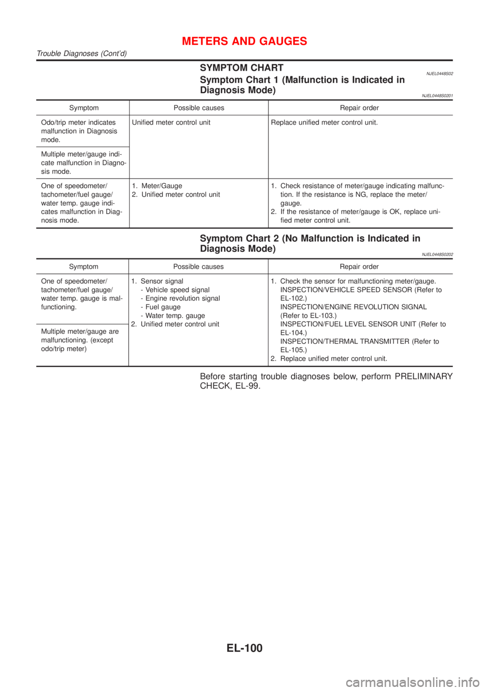
SYMPTOM CHARTNJEL0448S02Symptom Chart 1 (Malfunction is Indicated in
Diagnosis Mode)
NJEL0448S0201
Symptom Possible causes Repair order
Odo/trip meter indicates
malfunction in Diagnosis
mode.Unified meter control unit Replace unified meter control unit.
Multiple meter/gauge indi-
cate malfunction in Diagno-
sis mode.
One of speedometer/
tachometer/fuel gauge/
water temp. gauge indi-
cates malfunction in Diag-
nosis mode.1. Meter/Gauge
2. Unified meter control unit1. Check resistance of meter/gauge indicating malfunc-
tion. If the resistance is NG, replace the meter/
gauge.
2. If the resistance of meter/gauge is OK, replace uni-
fied meter control unit.
Symptom Chart 2 (No Malfunction is Indicated in
Diagnosis Mode)
NJEL0448S0202
Symptom Possible causes Repair order
One of speedometer/
tachometer/fuel gauge/
water temp. gauge is mal-
functioning.1. Sensor signal
- Vehicle speed signal
- Engine revolution signal
- Fuel gauge
- Water temp. gauge
2. Unified meter control unit1. Check the sensor for malfunctioning meter/gauge.
INSPECTION/VEHICLE SPEED SENSOR (Refer to
EL-102.)
INSPECTION/ENGINE REVOLUTION SIGNAL
(Refer to EL-103.)
INSPECTION/FUEL LEVEL SENSOR UNIT (Refer to
EL-104.)
INSPECTION/THERMAL TRANSMITTER (Refer to
EL-105.)
2. Replace unified meter control unit. Multiple meter/gauge are
malfunctioning. (except
odo/trip meter)
Before starting trouble diagnoses below, perform PRELIMINARY
CHECK, EL-99.
METERS AND GAUGES
Trouble Diagnoses (Cont'd)
EL-100
Page 2214 of 2493
INSPECTION/VEHICLE SPEED SENSOR=NJEL0448S04
1 CHECK VEHICLE SPEED SENSOR OUTPUT
1. Remove vehicle speed sensor from transmission.
2. Check voltage between combination meter terminal 5 and ground while quickly turning speed sensor pinion.
YEL795C
OK or NG
OK©Vehicle speed sensor is OK.
NG©GO TO 2.
2 CHECK VEHICLE SPEED SENSOR
Check resistance between vehicle speed sensor terminals 1 and 2.
SEL645WA
OK or NG
OK©Check the following.
+Harness between combination meter and vehicle speed sensor
+Vehicle speed sensor ground circuit
NG©Replace vehicle speed sensor.
METERS AND GAUGES
Trouble Diagnoses (Cont'd)
EL-102