Page 1735 of 2493
SBR307E
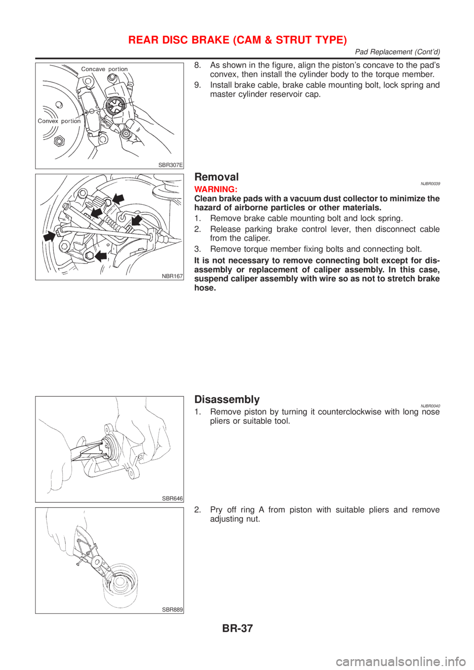
8. As shown in the figure, align the piston's concave to the pad's
convex, then install the cylinder body to the torque member.
9. Install brake cable, brake cable mounting bolt, lock spring and
master cylinder reservoir cap.
NBR167
RemovalNJBR0039WARNING:
Clean brake pads with a vacuum dust collector to minimize the
hazard of airborne particles or other materials.
1. Remove brake cable mounting bolt and lock spring.
2. Release parking brake control lever, then disconnect cable
from the caliper.
3. Remove torque member fixing bolts and connecting bolt.
It is not necessary to remove connecting bolt except for dis-
assembly or replacement of caliper assembly. In this case,
suspend caliper assembly with wire so as not to stretch brake
hose.
SBR646
DisassemblyNJBR00401. Remove piston by turning it counterclockwise with long nose
pliers or suitable tool.
SBR889
2. Pry off ring A from piston with suitable pliers and remove
adjusting nut.
REAR DISC BRAKE (CAM & STRUT TYPE)
Pad Replacement (Cont'd)
BR-37
Page 1741 of 2493
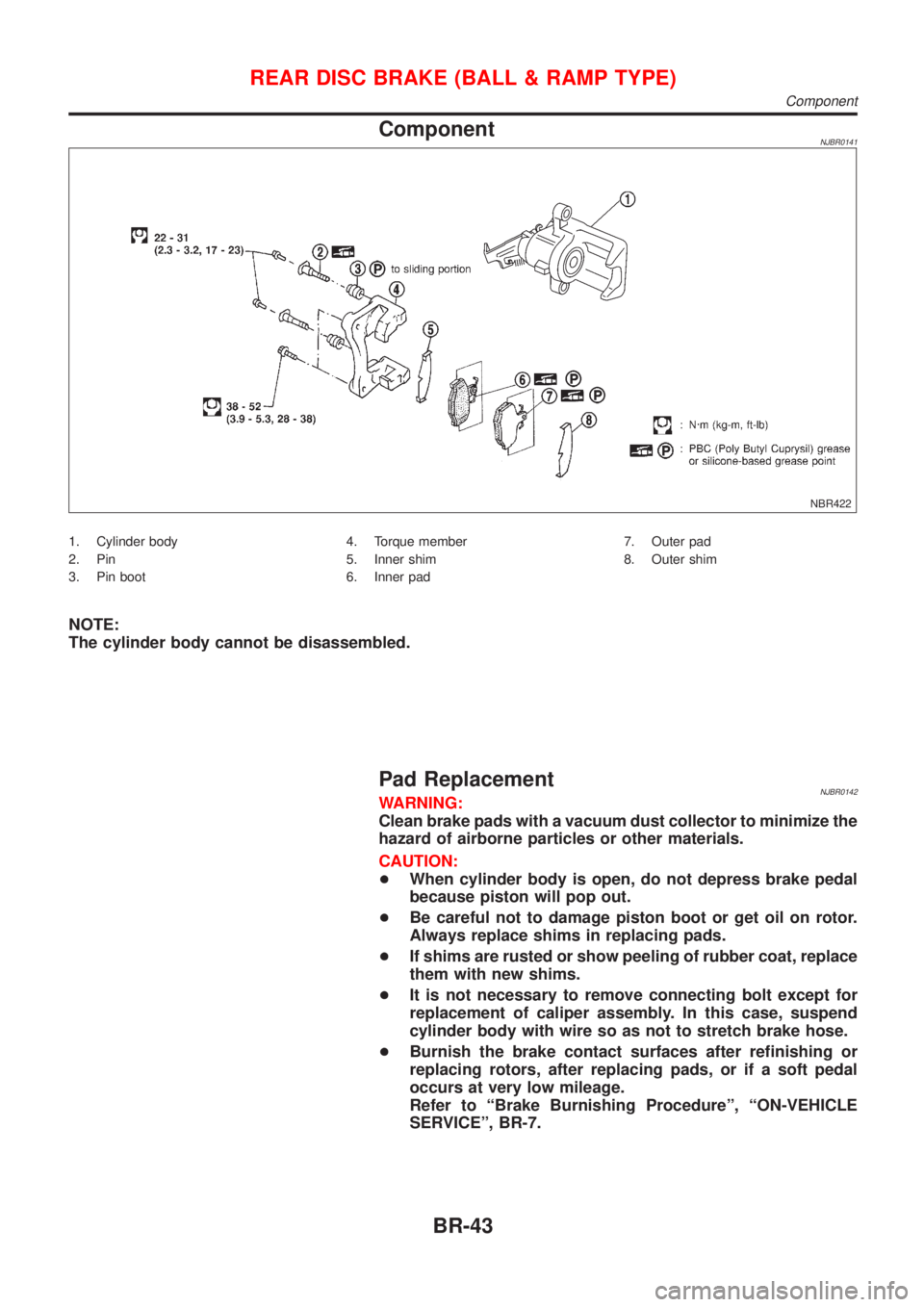
ComponentNJBR0141
NBR422
1. Cylinder body
2. Pin
3. Pin boot4. Torque member
5. Inner shim
6. Inner pad7. Outer pad
8. Outer shim
NOTE:
The cylinder body cannot be disassembled.
Pad ReplacementNJBR0142WARNING:
Clean brake pads with a vacuum dust collector to minimize the
hazard of airborne particles or other materials.
CAUTION:
+When cylinder body is open, do not depress brake pedal
because piston will pop out.
+Be careful not to damage piston boot or get oil on rotor.
Always replace shims in replacing pads.
+If shims are rusted or show peeling of rubber coat, replace
them with new shims.
+It is not necessary to remove connecting bolt except for
replacement of caliper assembly. In this case, suspend
cylinder body with wire so as not to stretch brake hose.
+Burnish the brake contact surfaces after refinishing or
replacing rotors, after replacing pads, or if a soft pedal
occurs at very low mileage.
Refer to ªBrake Burnishing Procedureº, ªON-VEHICLE
SERVICEº, BR-7.
REAR DISC BRAKE (BALL & RAMP TYPE)
Component
BR-43
Page 1743 of 2493
NBR427
RemovalNJBR0143WARNING:
Clean brake pads with a vacuum dust collector to minimize the
hazard of airborne particles or other materials.
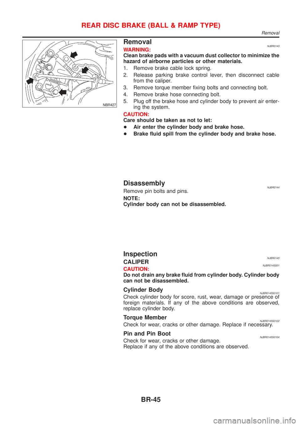
1. Remove brake cable lock spring.
2. Release parking brake control lever, then disconnect cable
from the caliper.
3. Remove torque member fixing bolts and connecting bolt.
4. Remove brake hose connecting bolt.
5. Plug off the brake hose and cylinder body to prevent air enter-
ing the system.
CAUTION:
Care should be taken as not to let:
+Air enter the cylinder body and brake hose.
+Brake fluid spill from the cylinder body and brake hose.
DisassemblyNJBR0144Remove pin bolts and pins.
NOTE:
Cylinder body can not be disassembled.
InspectionNJBR0145CALIPERNJBR0145S01CAUTION:
Do not drain any brake fluid from cylinder body. Cylinder body
can not be disassembled.
Cylinder BodyNJBR0145S0101Check cylinder body for score, rust, wear, damage or presence of
foreign materials. If any of the above conditions are observed,
replace cylinder body.
Torque MemberNJBR0145S0102Check for wear, cracks or other damage. Replace if necessary.
Pin and Pin BootNJBR0145S0104Check for wear, cracks or other damage.
Replace if any of the above conditions are observed.
REAR DISC BRAKE (BALL & RAMP TYPE)
Removal
BR-45
Page 1745 of 2493
ComponentsNJBR0044
NBR356
SBR897D
Removal and InstallationNJBR00451. To remove parking brake cable, first remove center console.
2. Disconnect warning lamp switch connector.
3. Remove adjusting nut.
4. Remove bolts and nuts securing parking brake cable.
5. Remove parking brake device.
SBR025D
6. Remove lock plate and disconnect cable (disc brake only).
For drum brake models, refer to ‘‘Removal’’, ‘‘REAR DRUM
BRAKE’’, BR-31.
InspectionNJBR00461. Check control lever for wear or other damage. Replace if nec-
essary.
2. Check wires for discontinuity or deterioration. Replace if nec-
essary.
3. Check warning lamp and switch. Replace if necessary.
4. Check parts at each connecting portion and, if found deformed
or damaged, replace.
PARKING BRAKE CONTROL
Components
BR-47
Page 1746 of 2493
SBR768E
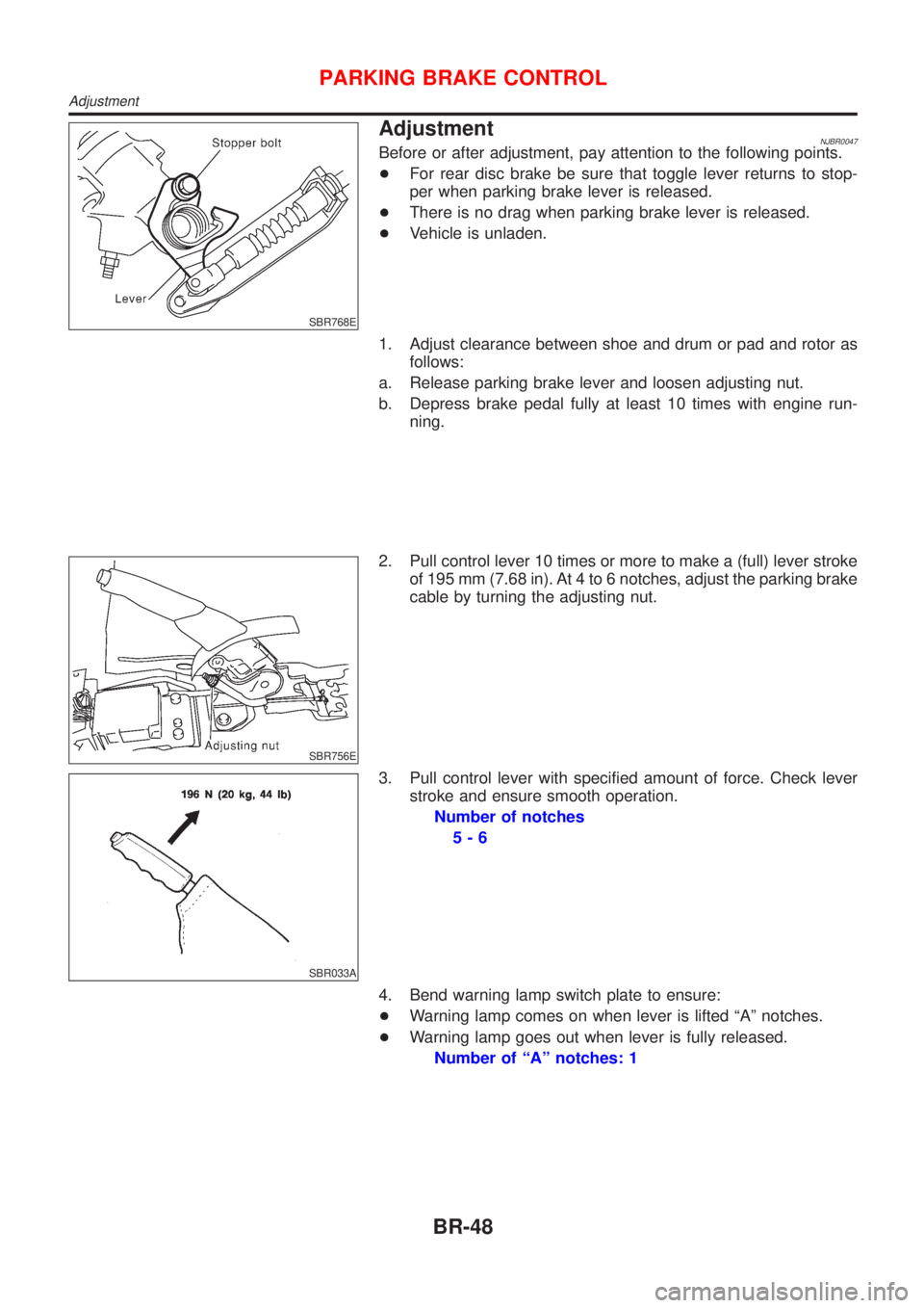
AdjustmentNJBR0047Before or after adjustment, pay attention to the following points.
+For rear disc brake be sure that toggle lever returns to stop-
per when parking brake lever is released.
+There is no drag when parking brake lever is released.
+Vehicle is unladen.
1. Adjust clearance between shoe and drum or pad and rotor as
follows:
a. Release parking brake lever and loosen adjusting nut.
b. Depress brake pedal fully at least 10 times with engine run-
ning.
SBR756E
2. Pull control lever 10 times or more to make a (full) lever stroke
of 195 mm (7.68 in). At 4 to 6 notches, adjust the parking brake
cable by turning the adjusting nut.
SBR033A
3. Pull control lever with specified amount of force. Check lever
stroke and ensure smooth operation.
Number of notches
5-6
4. Bend warning lamp switch plate to ensure:
+Warning lamp comes on when lever is lifted ªAº notches.
+Warning lamp goes out when lever is fully released.
Number of ªAº notches: 1
PARKING BRAKE CONTROL
Adjustment
BR-48
Page 1747 of 2493

PurposeNJBR0082The ABS consists of electronic and hydraulic components. It allows for control of braking force so that lock-
ing of the wheels can be avoided.
The ABS:
1) Ensures proper tracking performance through steering wheel operation.
2) Enables obstacles to be avoided through steering wheel operation.
3) Ensures vehicle stability by preventing flat spins.
ABS (Anti-Lock Brake System) OperationNJBR0083+When the vehicle speed is less than 10 km/h (6 MPH) this system does not work.
+The Anti-Lock Brake System (ABS) has self-test capabilities. The system turns on the ABS warning lamp
for 1 second after turning the ignition switch ON. The system performs another test the first time the vehicle
reaches 6 km/h (4 MPH). A mechanical noise may be heard as the ABS performs a self-test. This is a
normal part of the self-test feature. If a malfunction is found during this check, the ABS warning lamp will
come on.
+During ABS operation, a mechanical noise may be heard. This is a normal condition.
ABS Hydraulic CircuitNJBR0084
SBR757E
1. Inlet solenoid valve
2. Outlet solenoid valve
3. Reservoir4. Pump
5. Motor6. Bypass check valve
7. Damper
DESCRIPTIONABS
Purpose
BR-49
Page 1748 of 2493
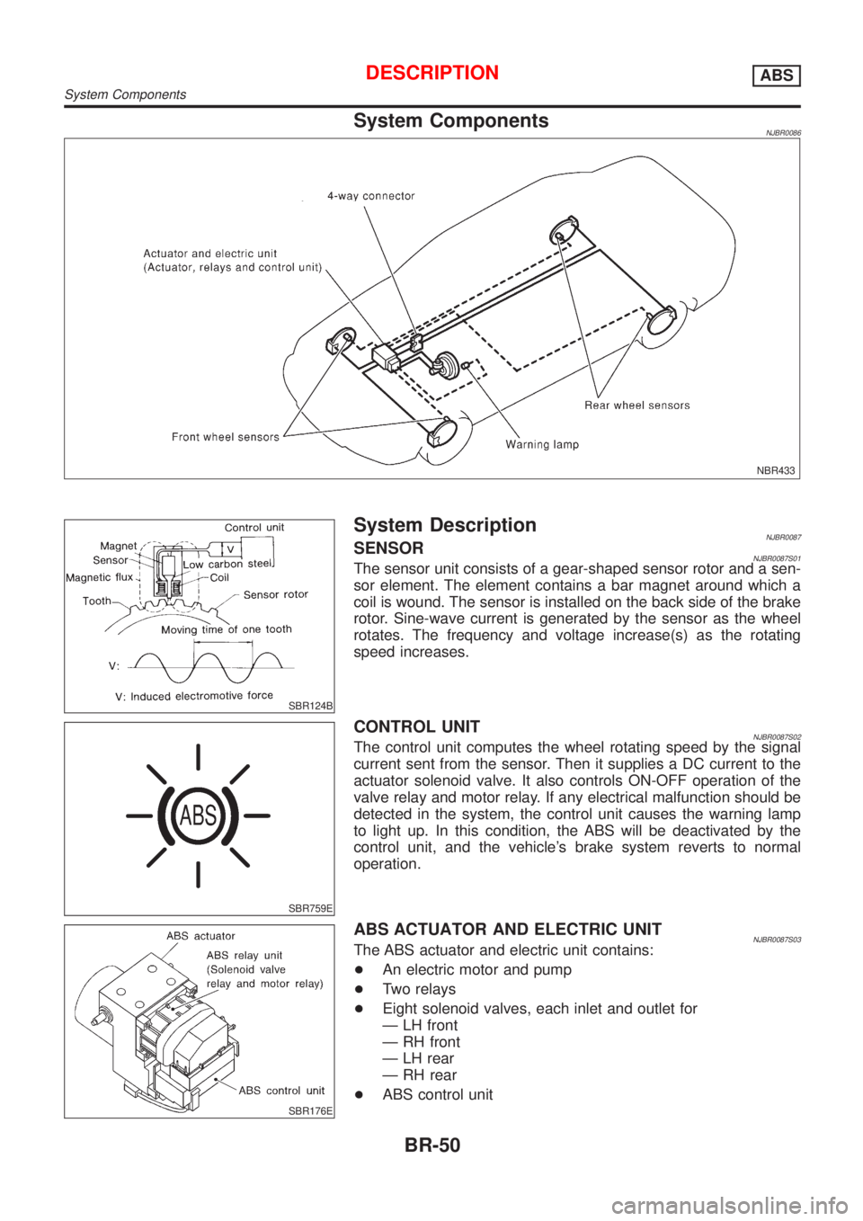
System ComponentsNJBR0086
NBR433
SBR124B
System DescriptionNJBR0087SENSORNJBR0087S01The sensor unit consists of a gear-shaped sensor rotor and a sen-
sor element. The element contains a bar magnet around which a
coil is wound. The sensor is installed on the back side of the brake
rotor. Sine-wave current is generated by the sensor as the wheel
rotates. The frequency and voltage increase(s) as the rotating
speed increases.
SBR759E
CONTROL UNITNJBR0087S02The control unit computes the wheel rotating speed by the signal
current sent from the sensor. Then it supplies a DC current to the
actuator solenoid valve. It also controls ON-OFF operation of the
valve relay and motor relay. If any electrical malfunction should be
detected in the system, the control unit causes the warning lamp
to light up. In this condition, the ABS will be deactivated by the
control unit, and the vehicle's brake system reverts to normal
operation.
SBR176E
ABS ACTUATOR AND ELECTRIC UNITNJBR0087S03The ABS actuator and electric unit contains:
+An electric motor and pump
+Two relays
+Eight solenoid valves, each inlet and outlet for
Ð LH front
Ð RH front
Ð LH rear
Ð RH rear
+ABS control unit
DESCRIPTIONABS
System Components
BR-50
Page 1756 of 2493
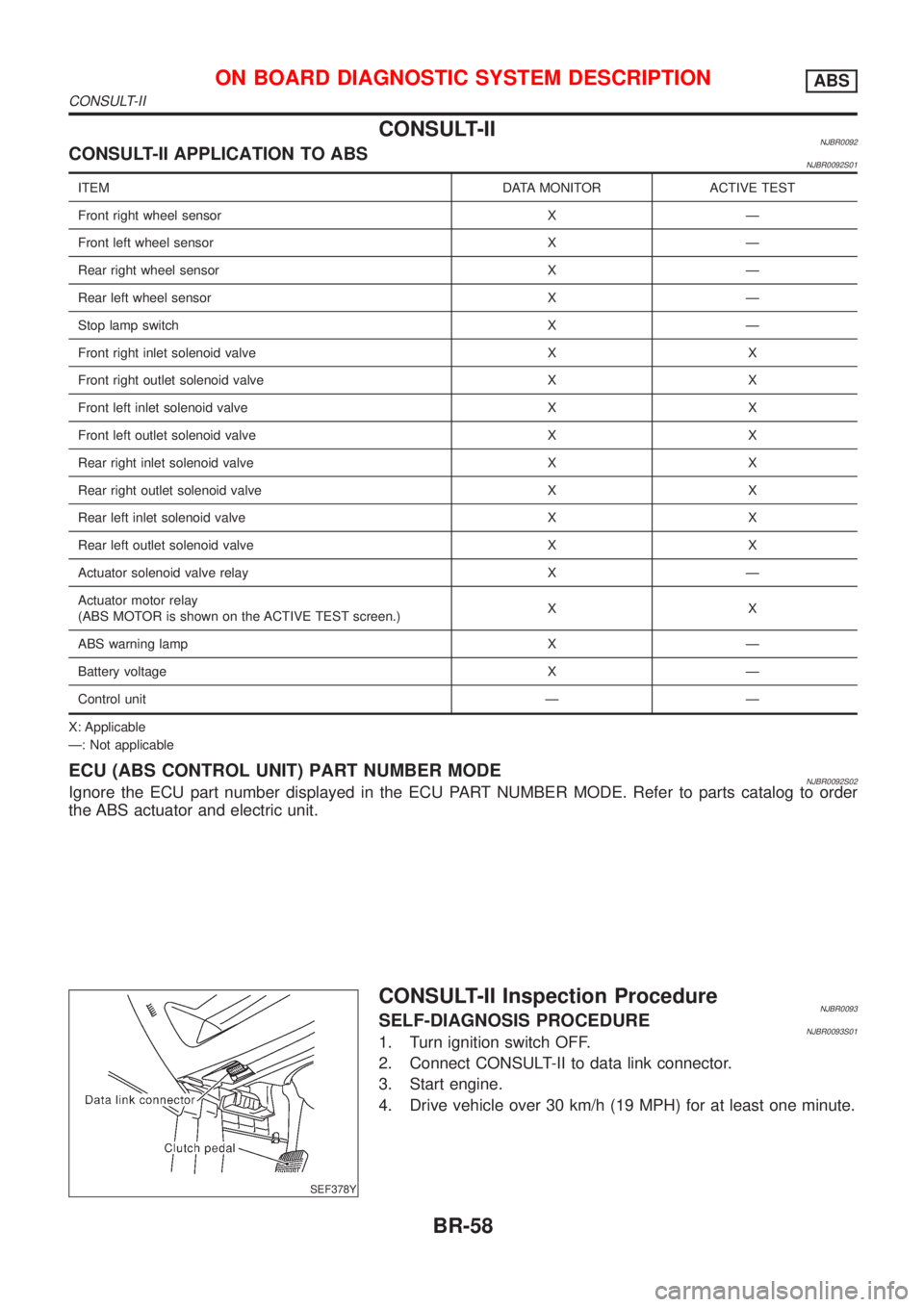
CONSULT-IINJBR0092CONSULT-II APPLICATION TO ABSNJBR0092S01
ITEM DATA MONITOR ACTIVE TEST
Front right wheel sensor X Ð
Front left wheel sensor X Ð
Rear right wheel sensor X Ð
Rear left wheel sensor X Ð
Stop lamp switch X Ð
Front right inlet solenoid valve X X
Front right outlet solenoid valve X X
Front left inlet solenoid valve X X
Front left outlet solenoid valve X X
Rear right inlet solenoid valve X X
Rear right outlet solenoid valve X X
Rear left inlet solenoid valve X X
Rear left outlet solenoid valve X X
Actuator solenoid valve relay X Ð
Actuator motor relay
(ABS MOTOR is shown on the ACTIVE TEST screen.)XX
ABS warning lamp X Ð
Battery voltage X Ð
Control unit Ð Ð
X: Applicable
Ð: Not applicable
ECU (ABS CONTROL UNIT) PART NUMBER MODENJBR0092S02Ignore the ECU part number displayed in the ECU PART NUMBER MODE. Refer to parts catalog to order
the ABS actuator and electric unit.
SEF378Y
CONSULT-II Inspection ProcedureNJBR0093SELF-DIAGNOSIS PROCEDURENJBR0093S011. Turn ignition switch OFF.
2. Connect CONSULT-II to data link connector.
3. Start engine.
4. Drive vehicle over 30 km/h (19 MPH) for at least one minute.
ON BOARD DIAGNOSTIC SYSTEM DESCRIPTIONABS
CONSULT-II
BR-58