2001 NISSAN ALMERA N16 warning
[x] Cancel search: warningPage 1694 of 2493
SRA806A
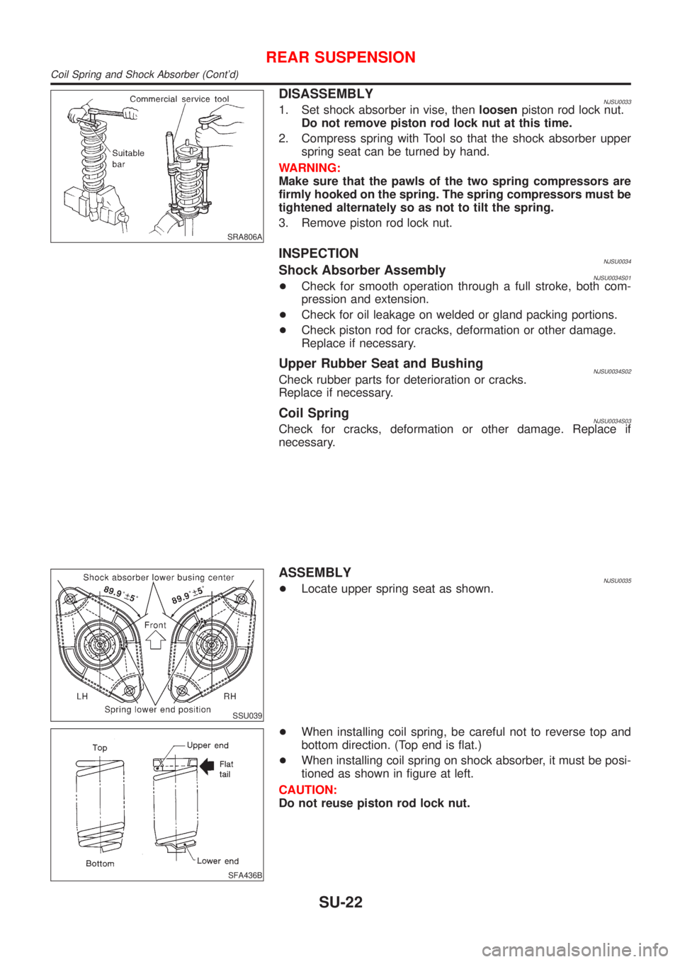
DISASSEMBLYNJSU00331. Set shock absorber in vise, thenloosenpiston rod lock nut.
Do not remove piston rod lock nut at this time.
2. Compress spring with Tool so that the shock absorber upper
spring seat can be turned by hand.
WARNING:
Make sure that the pawls of the two spring compressors are
firmly hooked on the spring. The spring compressors must be
tightened alternately so as not to tilt the spring.
3. Remove piston rod lock nut.
INSPECTIONNJSU0034Shock Absorber AssemblyNJSU0034S01+Check for smooth operation through a full stroke, both com-
pression and extension.
+Check for oil leakage on welded or gland packing portions.
+Check piston rod for cracks, deformation or other damage.
Replace if necessary.
Upper Rubber Seat and BushingNJSU0034S02Check rubber parts for deterioration or cracks.
Replace if necessary.
Coil SpringNJSU0034S03Check for cracks, deformation or other damage. Replace if
necessary.
SSU039
ASSEMBLYNJSU0035+Locate upper spring seat as shown.
SFA436B
+When installing coil spring, be careful not to reverse top and
bottom direction. (Top end is flat.)
+When installing coil spring on shock absorber, it must be posi-
tioned as shown in figure at left.
CAUTION:
Do not reuse piston rod lock nut.
REAR SUSPENSION
Coil Spring and Shock Absorber (Cont'd)
SU-22
Page 1700 of 2493

Inspection - Lining .....................................................33
Installation ..................................................................33
REAR DISC BRAKE (CAM & STRUT TYPE)..............35
Component ................................................................35
Pad Replacement ......................................................35
Removal .....................................................................37
Disassembly...............................................................37
Inspection...................................................................38
CALIPER.................................................................38
ROTOR...................................................................39
Assembly ...................................................................39
Installation ..................................................................42
REAR DISC BRAKE (BALL & RAMP TYPE)..............43
Component ................................................................43
Pad Replacement ......................................................43
Removal .....................................................................45
Disassembly...............................................................45
Inspection...................................................................45
CALIPER.................................................................45
ROTOR...................................................................46
Installation ..................................................................46
PARKING BRAKE CONTROL......................................47
Components...............................................................47
Removal and Installation ...........................................47
Inspection...................................................................47
Adjustment .................................................................48
ABS
DESCRIPTION...............................................................49
Purpose......................................................................49
ABS (Anti-Lock Brake System) Operation ................49
ABS Hydraulic Circuit ................................................49
System Components .................................................50
System Description ....................................................50
SENSOR.................................................................50
CONTROL UNIT......................................................50
ABS ACTUATOR AND ELECTRIC UNIT....................50
Component Parts and Harness Connector
Location .....................................................................52
Schematic ..................................................................53
Wiring Diagram - ABS - .............................................54
ON BOARD DIAGNOSTIC SYSTEM
DESCRIPTION...............................................................58
CONSULT-II ...............................................................58
CONSULT-II APPLICATION TO ABS..........................58
ECU (ABS CONTROL UNIT) PART NUMBER
MODE
.....................................................................58
CONSULT-II Inspection Procedure............................58
SELF-DIAGNOSIS PROCEDURE..............................58
SELF-DIAGNOSTIC RESULTS MODE.......................60
DATA MONITOR PROCEDURE................................61
ACTIVE TEST PROCEDURE....................................62
DATA MONITOR MODE...........................................63
ACTIVE TEST MODE...............................................63
TROUBLE DIAGNOSIS - INTRODUCTION..................64
How to Perform Trouble Diagnoses for Quick
and Accurate Repair ..................................................64
INTRODUCTION......................................................64
TROUBLE DIAGNOSIS - BASIC INSPECTION...........65
Preliminary Check......................................................65
Ground Circuit Check ................................................68
ABS ACTUATOR AND ELECTRIC UNIT GROUND.....68
TROUBLE DIAGNOSES FOR SELF-DIAGNOSTIC
ITEMS.............................................................................69
Wheel Sensor or Rotor ..............................................69
DIAGNOSTIC PROCEDURE.....................................69
ABS Actuator Solenoid Valve or Solenoid Valve
Relay ..........................................................................72
DIAGNOSTIC PROCEDURE.....................................72
Motor Relay or Motor.................................................75
DIAGNOSTIC PROCEDURE.....................................75
Low Voltage ...............................................................77
DIAGNOSTIC PROCEDURE.....................................77
Control Unit ................................................................79
DIAGNOSTIC PROCEDURE.....................................79
TROUBLE DIAGNOSES FOR SYMPTOMS.................80
1. ABS Works Frequently ..........................................80
2. Unexpected Pedal Action ......................................80
3. Long Stopping Distance ........................................81
4. ABS Does Not Work ..............................................82
5. Pedal Vibration and Noise.....................................83
6. ABS Warning Lamp Does Not Come On
When Ignition Switch Is Turned On...........................84
7. ABS Warning Lamp Stays On When Ignition
Switch Is Turned On ..................................................86
REMOVAL AND INSTALLATION.................................88
Wheel Sensors ..........................................................88
ABS Actuator and Electric Unit..................................89
REMOVAL...............................................................89
INSTALLATION........................................................89
Sensor Rotor..............................................................90
REMOVAL...............................................................90
INSTALLATION........................................................90
SERVICE DATA AND SPECIFICATIONS (SDS).........91
General Specifications ...............................................91
Disc Brake .................................................................91
Drum Brake................................................................91
Brake Pedal ...............................................................92
Parking Brake ............................................................92
CONTENTS(Cont'd)
BR-2
Page 1701 of 2493
Supplemental Restraint System (SRS) ªAIR
BAGº and ªSEAT BELT PRE-TENSIONERº
NJBR0139The Supplemental Restraint System such as ªAIR BAGº and ªSEAT BELT PRE-TENSIONERº used along with
a seat belt, helps to reduce the risk or severity of injury to the driver and front passenger for certain types of
collision. The SRS system composition which is available to NISSAN MODEL N16 is as follows (The compo-
sition varies according to the destination and optional equipment.):
+For a frontal collision
The Supplemental Restraint System consists of driver air bag module (located in the center of the steer-
ing wheel), front passenger air bag module (located on the instrument panel on passenger side), front seat
belt pre-tensioners, a diagnosis sensor unit, warning lamp, wiring harness and spiral cable.
+For a side collision
The Supplemental Restraint System consists of front side air bag module (located in the outer side of front
seat), side air bag (satellite) sensor, diagnosis sensor unit (one of components of air bags for a frontal
collision), wiring harness, warning lamp (one of components of air bags for a frontal collision).
Information necessary to service the system safely is included in theRS sectionof this Service Manual.
WARNING:
+To avoid rendering the SRS inoperative, which could increase the risk of personal injury or death
in the event of a collision which would result in air bag inflation, all maintenance should be per-
formed by an authorized NISSAN dealer.
+Improper maintenance, including incorrect removal and installation of the SRS, can lead to per-
sonal injury caused by unintentional activation of the system. For removal of Spiral Cable and Air
Bag Module, see the RS section.
+Do not use electrical test equipment on any circuit related to the SRS unless instructed to in this
Service Manual. SRS wiring harnesses can be identified by yellow harness connector.
SBR686C
Precautions for Brake SystemNJBR0002+Recommended fluid is brake fluid ªDOT 4º.
+Never reuse drained brake fluid.
+Be careful not to splash brake fluid on painted areas.
+To clean or wash all parts of master cylinder, disc brake
caliper and wheel cylinder, use clean brake fluid.
+Never use mineral oils such as gasoline or kerosene. They
will ruin rubber parts of the hydraulic system.
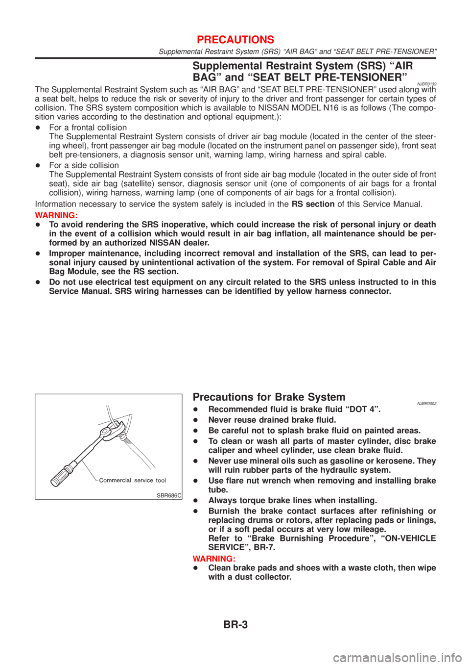
+Use flare nut wrench when removing and installing brake
tube.
+Always torque brake lines when installing.
+Burnish the brake contact surfaces after refinishing or
replacing drums or rotors, after replacing pads or linings,
or if a soft pedal occurs at very low mileage.
Refer to ªBrake Burnishing Procedureº, ªON-VEHICLE
SERVICEº, BR-7.
WARNING:
+Clean brake pads and shoes with a waste cloth, then wipe
with a dust collector.
PRECAUTIONS
Supplemental Restraint System (SRS) ªAIR BAGº and ªSEAT BELT PRE-TENSIONERº
BR-3
Page 1705 of 2493
SBR451D
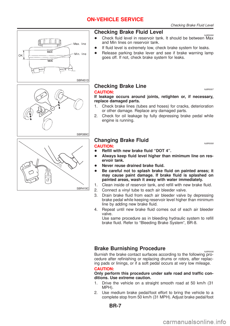
Checking Brake Fluid LevelNJBR0006+Check fluid level in reservoir tank. It should be between Max
and Min lines on reservoir tank.
+If fluid level is extremely low, check brake system for leaks.
+Release parking brake lever and see if brake warning lamp
goes off. If not, check brake system for leaks.
SBR389C
Checking Brake LineNJBR0007CAUTION:
If leakage occurs around joints, retighten or, if necessary,
replace damaged parts.
1. Check brake lines (tubes and hoses) for cracks, deterioration
or other damage. Replace any damaged parts.
2. Check for oil leakage by fully depressing brake pedal while
engine is running.
SBR419C
Changing Brake FluidNJBR0008CAUTION:
+Refill with new brake fluid ªDOT 4º.
+Always keep fluid level higher than minimum line on res-
ervoir tank.
+Never reuse drained brake fluid.
+Be careful not to splash brake fluid on painted areas; it
may cause paint damage. If brake fluid is splashed on
painted areas, wash it away with water immediately.
1. Clean inside of reservoir tank, and refill with new brake fluid.
2. Connect a vinyl tube to each air bleeder valve.
3. Drain brake fluid from each air bleeder valve by depressing
brake pedal while keeping reservoir level higher than minimum
line by adding new brake fluid.
4. Repeat until new brake fluid comes out of each air bleeder
valve.
Use same procedure as in bleeding hydraulic system to refill
brake fluid. Refer to ªBleeding Brake Systemº, BR-8.
Brake Burnishing ProcedureNJBR0036Burnish the brake contact surfaces according to the following pro-
cedure after refinishing or replacing drums or rotors, after replac-
ing pads or linings, or if a soft pedal occurs at very low mileage.
CAUTION:
Only perform this procedure under safe road and traffic con-
ditions. Use extreme caution.
1. Drive the vehicle on a straight smooth road at 50 km/h (31
MPH).
2. Use medium brake pedal/foot effort to bring the vehicle to a
complete stop from 50 km/h (31 MPH). Adjust brake pedal/foot
ON-VEHICLE SERVICE
Checking Brake Fluid Level
BR-7
Page 1725 of 2493
ComponentNJBR0030
NBR429
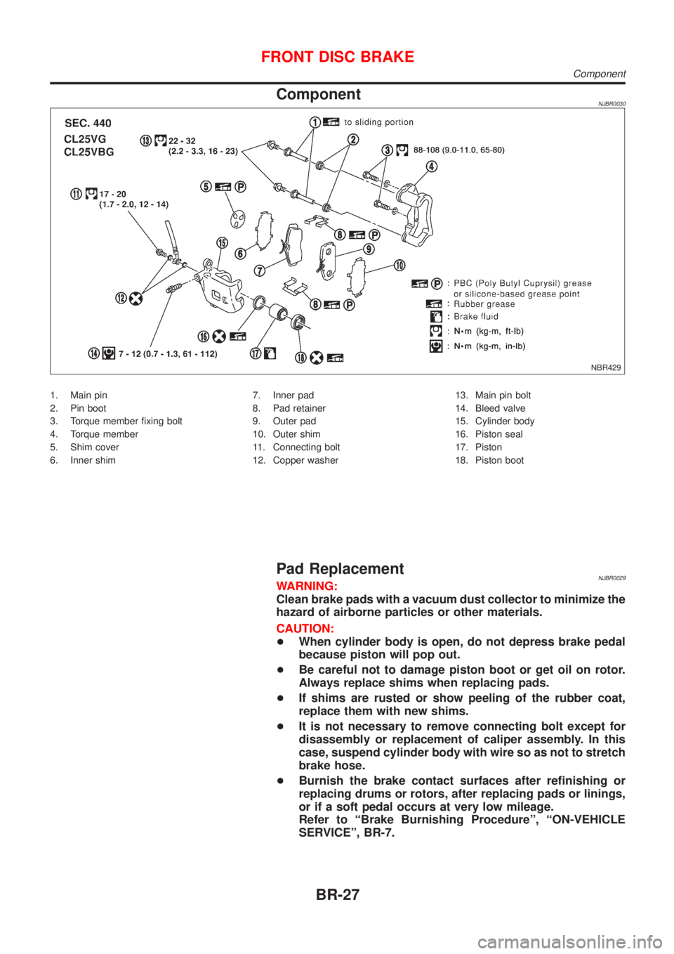
1. Main pin
2. Pin boot
3. Torque member fixing bolt
4. Torque member
5. Shim cover
6. Inner shim7. Inner pad
8. Pad retainer
9. Outer pad
10. Outer shim
11. Connecting bolt
12. Copper washer13. Main pin bolt
14. Bleed valve
15. Cylinder body
16. Piston seal
17. Piston
18. Piston boot
Pad ReplacementNJBR0029WARNING:
Clean brake pads with a vacuum dust collector to minimize the
hazard of airborne particles or other materials.
CAUTION:
+When cylinder body is open, do not depress brake pedal
because piston will pop out.
+Be careful not to damage piston boot or get oil on rotor.
Always replace shims when replacing pads.
+If shims are rusted or show peeling of the rubber coat,
replace them with new shims.
+It is not necessary to remove connecting bolt except for
disassembly or replacement of caliper assembly. In this
case, suspend cylinder body with wire so as not to stretch
brake hose.
+Burnish the brake contact surfaces after refinishing or
replacing drums or rotors, after replacing pads or linings,
or if a soft pedal occurs at very low mileage.
Refer to ªBrake Burnishing Procedureº, ªON-VEHICLE
SERVICEº, BR-7.
FRONT DISC BRAKE
Component
BR-27
Page 1726 of 2493
SBR976B
SBR932C
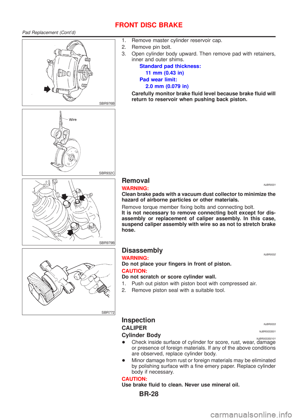
1. Remove master cylinder reservoir cap.
2. Remove pin bolt.
3. Open cylinder body upward. Then remove pad with retainers,
inner and outer shims.
Standard pad thickness:
11 mm (0.43 in)
Pad wear limit:
2.0 mm (0.079 in)
Carefully monitor brake fluid level because brake fluid will
return to reservoir when pushing back piston.
SBR979B
RemovalNJBR0031WARNING:
Clean brake pads with a vacuum dust collector to minimize the
hazard of airborne particles or other materials.
Remove torque member fixing bolts and connecting bolt.
It is not necessary to remove connecting bolt except for dis-
assembly or replacement of caliper assembly. In this case,
suspend caliper assembly with wire so as not to stretch brake
hose.
SBR772
DisassemblyNJBR0032WARNING:
Do not place your fingers in front of piston.
CAUTION:
Do not scratch or score cylinder wall.
1. Push out piston with piston boot with compressed air.
2. Remove piston seal with a suitable tool.
InspectionNJBR0033CALIPERNJBR0033S01Cylinder BodyNJBR0033S0101+Check inside surface of cylinder for score, rust, wear, damage
or presence of foreign materials. If any of the above conditions
are observed, replace cylinder body.
+Minor damage from rust or foreign materials may be eliminated
by polishing surface with a fine emery paper. Replace cylinder
body if necessary.
CAUTION:
Use brake fluid to clean. Never use mineral oil.
FRONT DISC BRAKE
Pad Replacement (Cont'd)
BR-28
Page 1729 of 2493
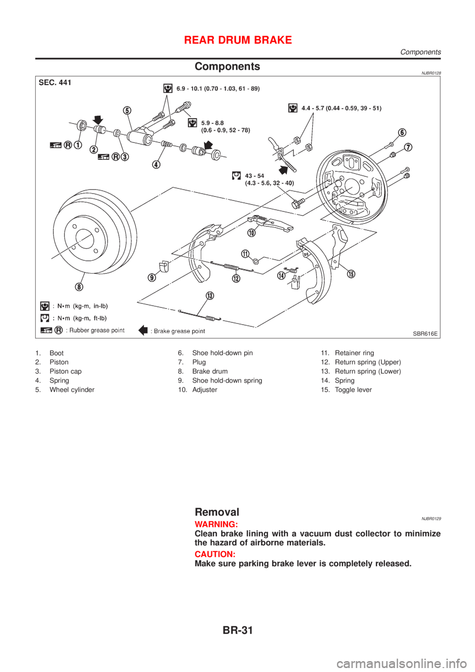
ComponentsNJBR0128
SBR616E
1. Boot
2. Piston
3. Piston cap
4. Spring
5. Wheel cylinder6. Shoe hold-down pin
7. Plug
8. Brake drum
9. Shoe hold-down spring
10. Adjuster11. Retainer ring
12. Return spring (Upper)
13. Return spring (Lower)
14. Spring
15. Toggle lever
RemovalNJBR0129WARNING:
Clean brake lining with a vacuum dust collector to minimize
the hazard of airborne materials.
CAUTION:
Make sure parking brake lever is completely released.
REAR DRUM BRAKE
Components
BR-31
Page 1733 of 2493
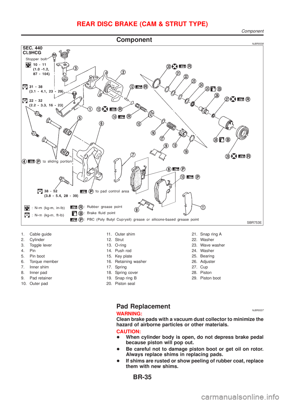
ComponentNJBR0038
SBR753E
1. Cable guide
2. Cylinder
3. Toggle lever
4. Pin
5. Pin boot
6. Torque member
7. Inner shim
8. Inner pad
9. Pad retainer
10. Outer pad11. Outer shim
12. Strut
13. O-ring
14. Push rod
15. Key plate
16. Retaining washer
17. Spring
18. Spring cover
19. Snap ring B
20. Piston seal21. Snap ring A
22. Washer
23. Wave washer
24. Washer
25. Bearing
26. Adjuster
27. Cup
28. Piston
29. Piston boot
Pad ReplacementNJBR0037WARNING:
Clean brake pads with a vacuum dust collector to minimize the
hazard of airborne particles or other materials.
CAUTION:
+When cylinder body is open, do not depress brake pedal
because piston will pop out.
+Be careful not to damage piston boot or get oil on rotor.
Always replace shims in replacing pads.
+If shims are rusted or show peeling of rubber coat, replace
them with new shims.
REAR DISC BRAKE (CAM & STRUT TYPE)
Component
BR-35