2001 NISSAN ALMERA N16 warning
[x] Cancel search: warningPage 1014 of 2493
SMA803A
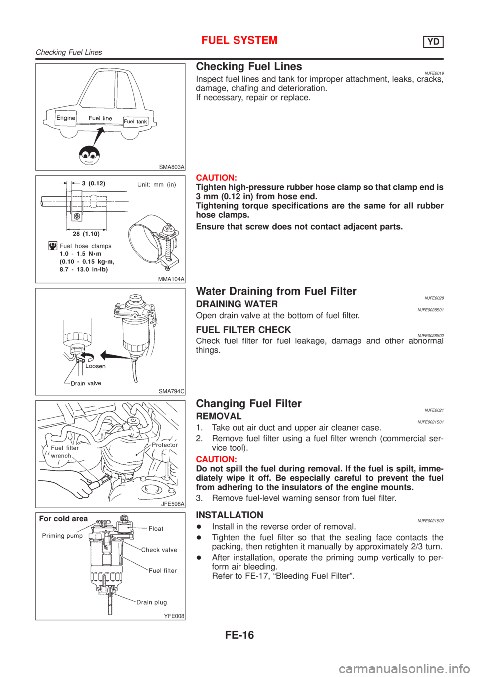
Checking Fuel LinesNJFE0019Inspect fuel lines and tank for improper attachment, leaks, cracks,
damage, chafing and deterioration.
If necessary, repair or replace.
MMA104A
CAUTION:
Tighten high-pressure rubber hose clamp so that clamp end is
3 mm (0.12 in) from hose end.
Tightening torque specifications are the same for all rubber
hose clamps.
Ensure that screw does not contact adjacent parts.
SMA794C
Water Draining from Fuel FilterNJFE0028DRAINING WATERNJFE0028S01Open drain valve at the bottom of fuel filter.
FUEL FILTER CHECKNJFE0028S02Check fuel filter for fuel leakage, damage and other abnormal
things.
JFE598A
Changing Fuel FilterNJFE0021REMOVALNJFE0021S011. Take out air duct and upper air cleaner case.
2. Remove fuel filter using a fuel filter wrench (commercial ser-
vice tool).
CAUTION:
Do not spill the fuel during removal. If the fuel is spilt, imme-
diately wipe it off. Be especially careful to prevent the fuel
from adhering to the insulators of the engine mounts.
3. Remove fuel-level warning sensor from fuel filter.
YFE008
INSTALLATIONNJFE0021S02+Install in the reverse order of removal.
+Tighten the fuel filter so that the sealing face contacts the
packing, then retighten it manually by approximately 2/3 turn.
+After installation, operate the priming pump vertically to per-
form air bleeding.
Refer to FE-17, ªBleeding Fuel Filterº.
FUEL SYSTEMYD
Checking Fuel Lines
FE-16
Page 1015 of 2493
JEM238G
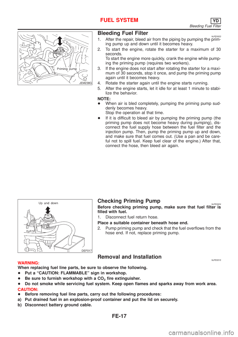
Bleeding Fuel FilterNJFE00231. After the repair, bleed air from the piping by pumping the prim-
ing pump up and down until it becomes heavy.
2. To start the engine, rotate the starter for a maximum of 30
seconds.
To start the engine more quickly, crank the engine while pump-
ing the priming pump (requires two workers).
3. If the engine does not start after rotating the starter for a maxi-
mum of 30 seconds, stop it once, and pump the priming pump
again until it becomes heavy.
4. Rotate the starter again until the engine starts running.
5. After the engine starts, let it idle for at least 1 minute to stabi-
lize the behavior.
NOTE:
+When air is bled completely, pumping the priming pump sud-
denly becomes heavy.
Stop the operation at that time.
+If it is difficult to bleed air by pumping the priming pump (the
priming pump does not become heavy during pumping), dis-
connect the fuel supply hose between the fuel filter and the
injection pump. Then, pump the priming pump up and down,
and make sure that fuel comes out. (Use a pan and be care-
ful not to spill fuel. Keep fuel clear of the engine.) After that,
connect the hose, then bleed air again.
DEF017
Checking Priming PumpNJFE0024Before checking priming pump, make sure that fuel filter is
filled with fuel.
1. Disconnect fuel return hose.
Place a suitable container beneath hose end.
2. Pump priming pump and check that the fuel overflows from the
hose end. If not, replace priming pump.
Removal and InstallationNJFE0015WARNING:
When replacing fuel line parts, be sure to observe the following.
+Put a ªCAUTION: FLAMMABLEº sign in workshop.
+Be sure to furnish workshop with a CO
2fire extinguisher.
+Do not smoke while servicing fuel system. Keep open flames and sparks away from work area.
CAUTION:
+Before removing fuel line parts, carry out the following procedures:
a) Put drained fuel in an explosion-proof container and put the lid on securely.
b) Disconnect battery ground cable.
FUEL SYSTEMYD
Bleeding Fuel Filter
FE-17
Page 1028 of 2493
SBR820BA
PrecautionsNJCL0001+Recommended fluid is brake fluid ªDOT 3º or ªDOT 4º
(Europe). Refer to MA-20, ªFluid and Lubricantsº.
+Never reuse drained brake fluid.
+Be careful not to splash brake fluid on painted areas.
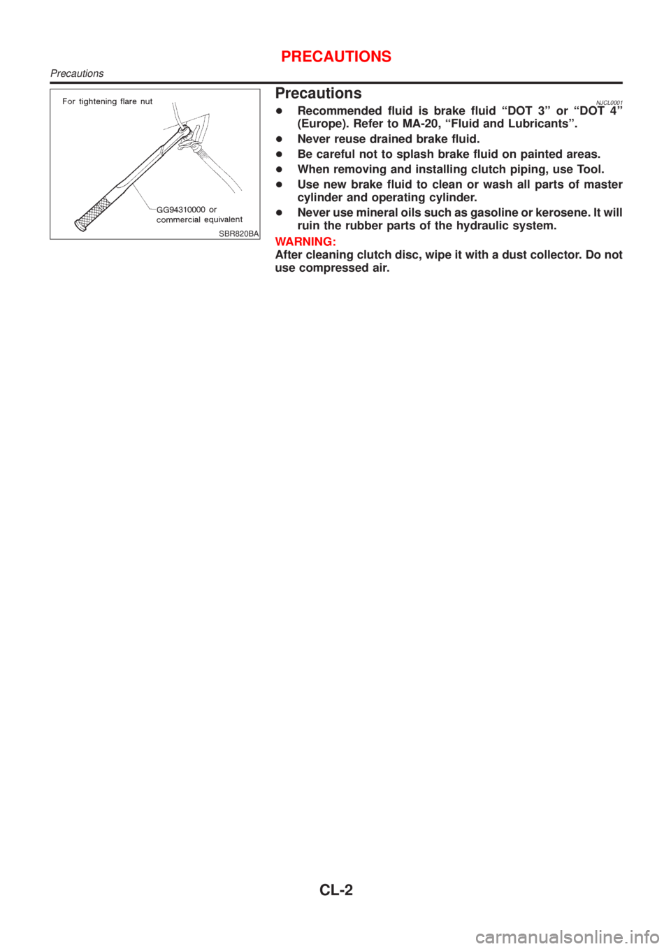
+When removing and installing clutch piping, use Tool.
+Use new brake fluid to clean or wash all parts of master
cylinder and operating cylinder.
+Never use mineral oils such as gasoline or kerosene. It will
ruin the rubber parts of the hydraulic system.
WARNING:
After cleaning clutch disc, wipe it with a dust collector. Do not
use compressed air.
PRECAUTIONS
Precautions
CL-2
Page 1193 of 2493
Supplemental Restraint System (SRS) ªAIR
BAGº and ªSEAT BELT PRE-TENSIONERº
NJAT0249The Supplemental Restraint System such as ªAIR BAGº and ªSEAT BELT PRE-TENSIONERº used along with
a seat belt, helps to reduce the risk or severity of injury to the driver and front passenger for certain types of
collision. The SRS system composition which is available to NISSAN MODEL N16 is as follows (The compo-
sition varies according to the destination and optional equipment.):
+For a frontal collision
The Supplemental Restraint System consists of driver air bag module (located in the center of the steer-
ing wheel), front passenger air bag module (located on the instrument panel on passenger side), front seat
belt pre-tensioners, a diagnosis sensor unit, warning lamp, wiring harness and spiral cable.
+For a side collision
The Supplemental Restraint System consists of front side air bag module (located in the outer side of front
seat), side air bag (satellite) sensor, diagnosis sensor unit (one of components of air bags for a frontal
collision), wiring harness, warning lamp (one of components of air bags for a frontal collision).
Information necessary to service the system safely is included in theRS sectionof this Service Manual.
WARNING:
+To avoid rendering the SRS inoperative, which could increase the risk of personal injury or death
in the event of a collision which would result in air bag inflation, all maintenance should be per-
formed by an authorized NISSAN dealer.
+Improper maintenance, including incorrect removal and installation of the SRS, can lead to per-
sonal injury caused by unintentional activation of the system. For removal of Spiral Cable and Air
Bag Module, see the RS section.
+Do not use electrical test equipment on any circuit related to the SRS unless instructed to in this
Service Manual. Spiral cable and wiring harnesses covered with yellow insulation tape either just
before the harness connectors or for the complete harness are related to the SRS.
Precautions for On Board Diagnostic (EURO-
OBD) System of A/T and Engine Ð Euro-OBD
Ð
NJAT0245The ECM has an on board diagnostic system. It will light up the malfunction indicator lamp (MIL) to warn the
driver of a malfunction causing emission deterioration.
CAUTION:
+Be sure to turn the ignition switch ªOFFº and disconnect the negative battery terminal before any
repair or inspection work. The open/short circuit of related switches, sensors, solenoid valves, etc.
will cause the MIL to light up.
+Be sure to connect and lock the connectors securely after work. A loose (unlocked) connector will
cause the MIL to light up due to an open circuit. (Be sure the connector is free from water, grease,
dirt, bent terminals, etc.)
+Be sure to route and secure the harnesses properly after work. Interference of the harness with a
bracket, etc. may cause the MIL to light up due to a short circuit.
+Be sure to connect rubber tubes properly after work. A misconnected or disconnected rubber tube
may cause the MIL to light up due to a malfunction of the EGR system or fuel injection system,
etc.
+Be sure to erase the unnecessary malfunction information (repairs completed) from the TCM and
ECM before returning the vehicle to the customer.
SEF289H
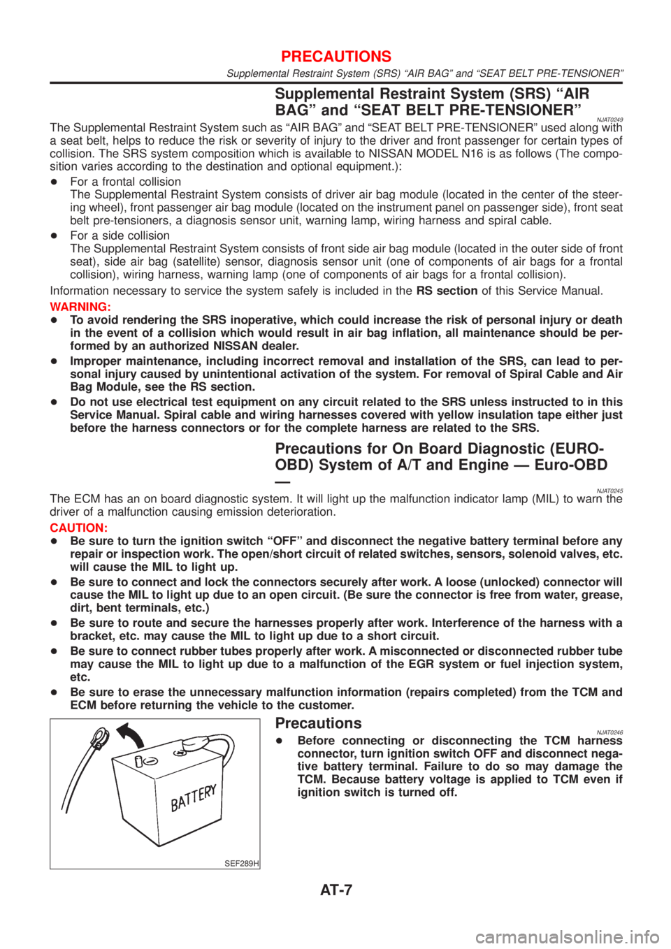
PrecautionsNJAT0246+Before connecting or disconnecting the TCM harness
connector, turn ignition switch OFF and disconnect nega-
tive battery terminal. Failure to do so may damage the
TCM. Because battery voltage is applied to TCM even if
ignition switch is turned off.
PRECAUTIONS
Supplemental Restraint System (SRS) ªAIR BAGº and ªSEAT BELT PRE-TENSIONERº
AT-7
Page 1238 of 2493
SAT964I
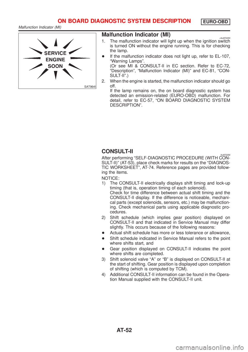
Malfunction Indicator (MI)=NJAT02551. The malfunction indicator will light up when the ignition switch
is turned ON without the engine running. This is for checking
the lamp.
+If the malfunction indicator does not light up, refer to EL-107,
ªWarning Lampsº.
(Or see MI & CONSULT-II in EC section. Refer to EC-72,
ªDescriptionº, ªMalfunction Indicator (MI)º and EC-81, ªCON-
SULT-IIº.)
2. When the engine is started, the malfunction indicator should go
off.
If the lamp remains on, the on board diagnostic system has
detected an emission-related (EURO-OBD) malfunction. For
detail, refer to EC-57, ªON BOARD DIAGNOSTIC SYSTEM
DESCRIPTIONº.
CONSULT-IINJAT0256After performing ªSELF-DIAGNOSTIC PROCEDURE (WITH CON-
SULT-II)º (AT-53), place check marks for results on the ªDIAGNOS-
TIC WORKSHEETº, AT-74. Reference pages are provided follow-
ing the items.
NOTICE:
1) The CONSULT-II electrically displays shift timing and lock-up
timing (that is, operation timing of each solenoid).
Check for time difference between actual shift timing and the
CONSULT-II display. If the difference is noticeable, mechani-
cal parts (except solenoids, sensors, etc.) may be malfunction-
ing. Check mechanical parts using applicable diagnostic pro-
cedures.
2) Shift schedule (which implies gear position) displayed on
CONSULT-II and that indicated in Service Manual may differ
slightly. This occurs because of the following reasons:
+Actual shift schedule has more or less tolerance or allowance,
+Shift schedule indicated in Service Manual refers to the point
where shifts start, and
+Gear position displayed on CONSULT-II indicates the point
where shifts are completed.
3) Shift solenoid valve ªAº or ªBº is displayed on CONSULT-II at
the start of shifting. Gear position is displayed upon completion
of shifting (which is computed by TCM).
4) Additional CONSULT-II information can be found in the Opera-
tion Manual supplied with the CONSULT-II unit.
ON BOARD DIAGNOSTIC SYSTEM DESCRIPTIONEURO-OBD
Malfunction Indicator (MI)
AT-52
Page 1680 of 2493
AFA050
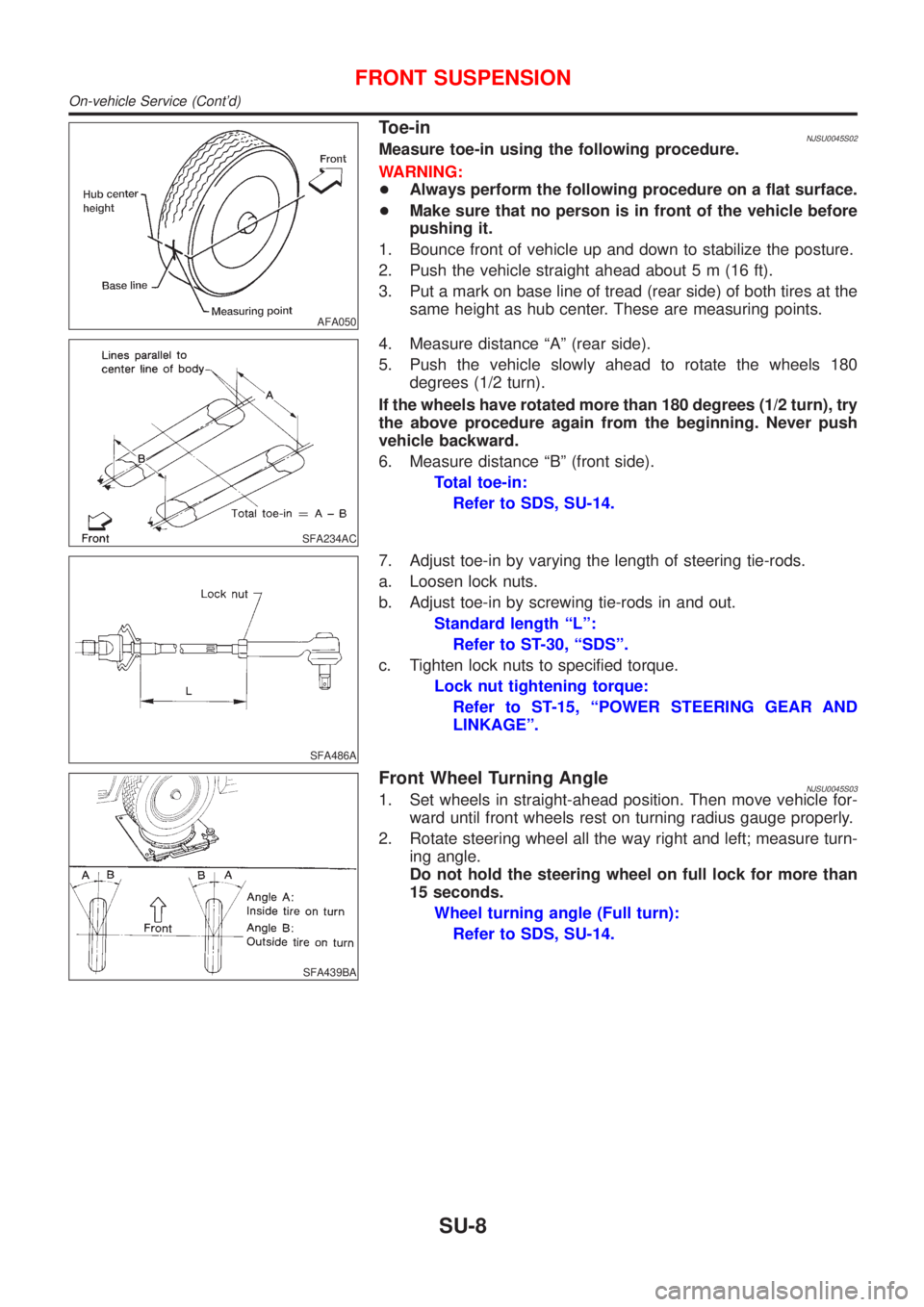
Toe-inNJSU0045S02Measure toe-in using the following procedure.
WARNING:
+Always perform the following procedure on a flat surface.
+Make sure that no person is in front of the vehicle before
pushing it.
1. Bounce front of vehicle up and down to stabilize the posture.
2. Push the vehicle straight ahead about 5 m (16 ft).
3. Put a mark on base line of tread (rear side) of both tires at the
same height as hub center. These are measuring points.
SFA234AC
4. Measure distance ªAº (rear side).
5. Push the vehicle slowly ahead to rotate the wheels 180
degrees (1/2 turn).
If the wheels have rotated more than 180 degrees (1/2 turn), try
the above procedure again from the beginning. Never push
vehicle backward.
6. Measure distance ªBº (front side).
Total toe-in:
Refer to SDS, SU-14.
SFA486A
7. Adjust toe-in by varying the length of steering tie-rods.
a. Loosen lock nuts.
b. Adjust toe-in by screwing tie-rods in and out.
Standard length ªLº:
Refer to ST-30, ªSDSº.
c. Tighten lock nuts to specified torque.
Lock nut tightening torque:
Refer to ST-15, ªPOWER STEERING GEAR AND
LINKAGEº.
SFA439BA
Front Wheel Turning AngleNJSU0045S031. Set wheels in straight-ahead position. Then move vehicle for-
ward until front wheels rest on turning radius gauge properly.
2. Rotate steering wheel all the way right and left; measure turn-
ing angle.
Do not hold the steering wheel on full lock for more than
15 seconds.
Wheel turning angle (Full turn):
Refer to SDS, SU-14.
FRONT SUSPENSION
On-vehicle Service (Cont'd)
SU-8
Page 1682 of 2493
SFA956A
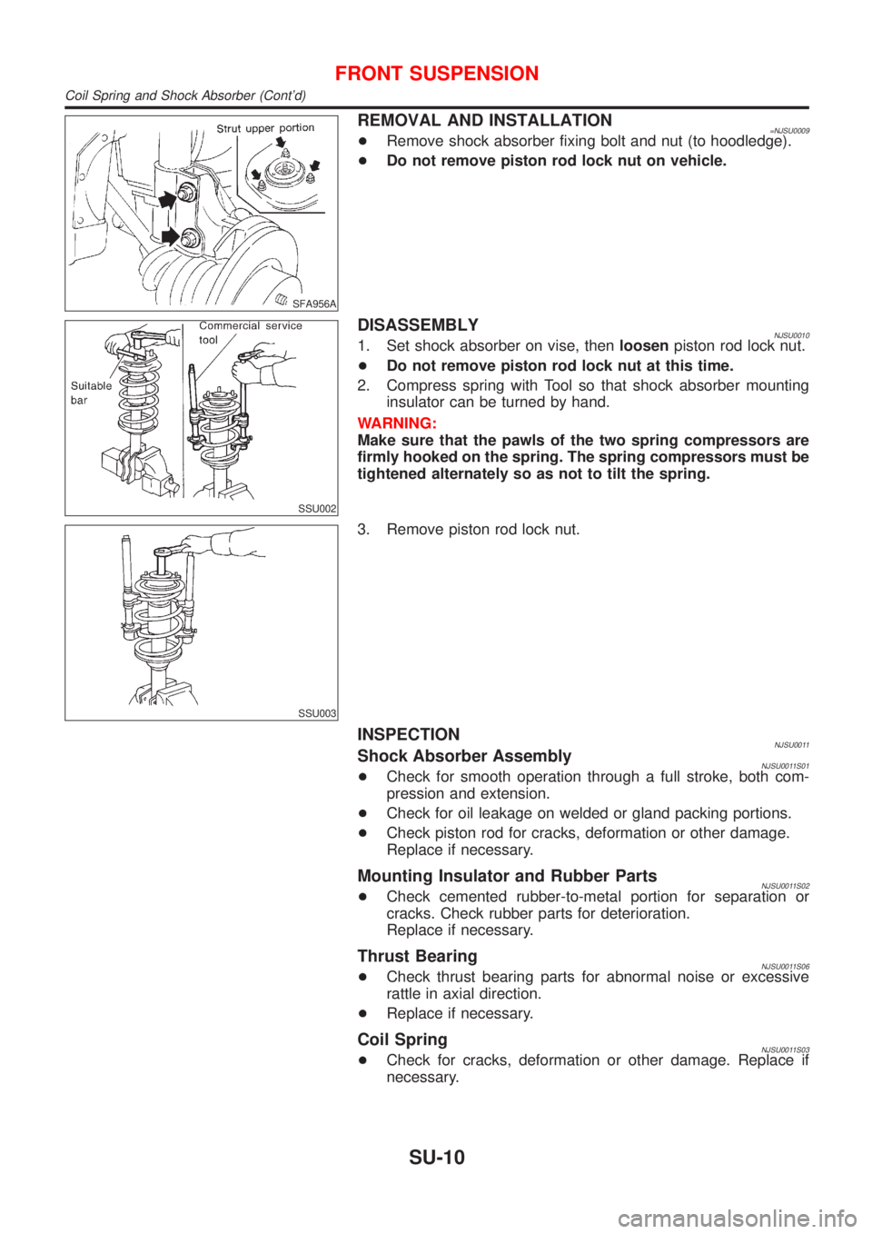
REMOVAL AND INSTALLATION=NJSU0009+Remove shock absorber fixing bolt and nut (to hoodledge).
+Do not remove piston rod lock nut on vehicle.
SSU002
DISASSEMBLYNJSU00101. Set shock absorber on vise, thenloosenpiston rod lock nut.
+Do not remove piston rod lock nut at this time.
2. Compress spring with Tool so that shock absorber mounting
insulator can be turned by hand.
WARNING:
Make sure that the pawls of the two spring compressors are
firmly hooked on the spring. The spring compressors must be
tightened alternately so as not to tilt the spring.
SSU003
3. Remove piston rod lock nut.
INSPECTIONNJSU0011Shock Absorber AssemblyNJSU0011S01+Check for smooth operation through a full stroke, both com-
pression and extension.
+Check for oil leakage on welded or gland packing portions.
+Check piston rod for cracks, deformation or other damage.
Replace if necessary.
Mounting Insulator and Rubber PartsNJSU0011S02+Check cemented rubber-to-metal portion for separation or
cracks. Check rubber parts for deterioration.
Replace if necessary.
Thrust BearingNJSU0011S06+Check thrust bearing parts for abnormal noise or excessive
rattle in axial direction.
+Replace if necessary.
Coil SpringNJSU0011S03+Check for cracks, deformation or other damage. Replace if
necessary.
FRONT SUSPENSION
Coil Spring and Shock Absorber (Cont'd)
SU-10
Page 1691 of 2493
5. Check steering linkage for looseness.
6. Check that front shock absorbers work properly.
7. Check vehicle posture (Unladen).
SFA948A
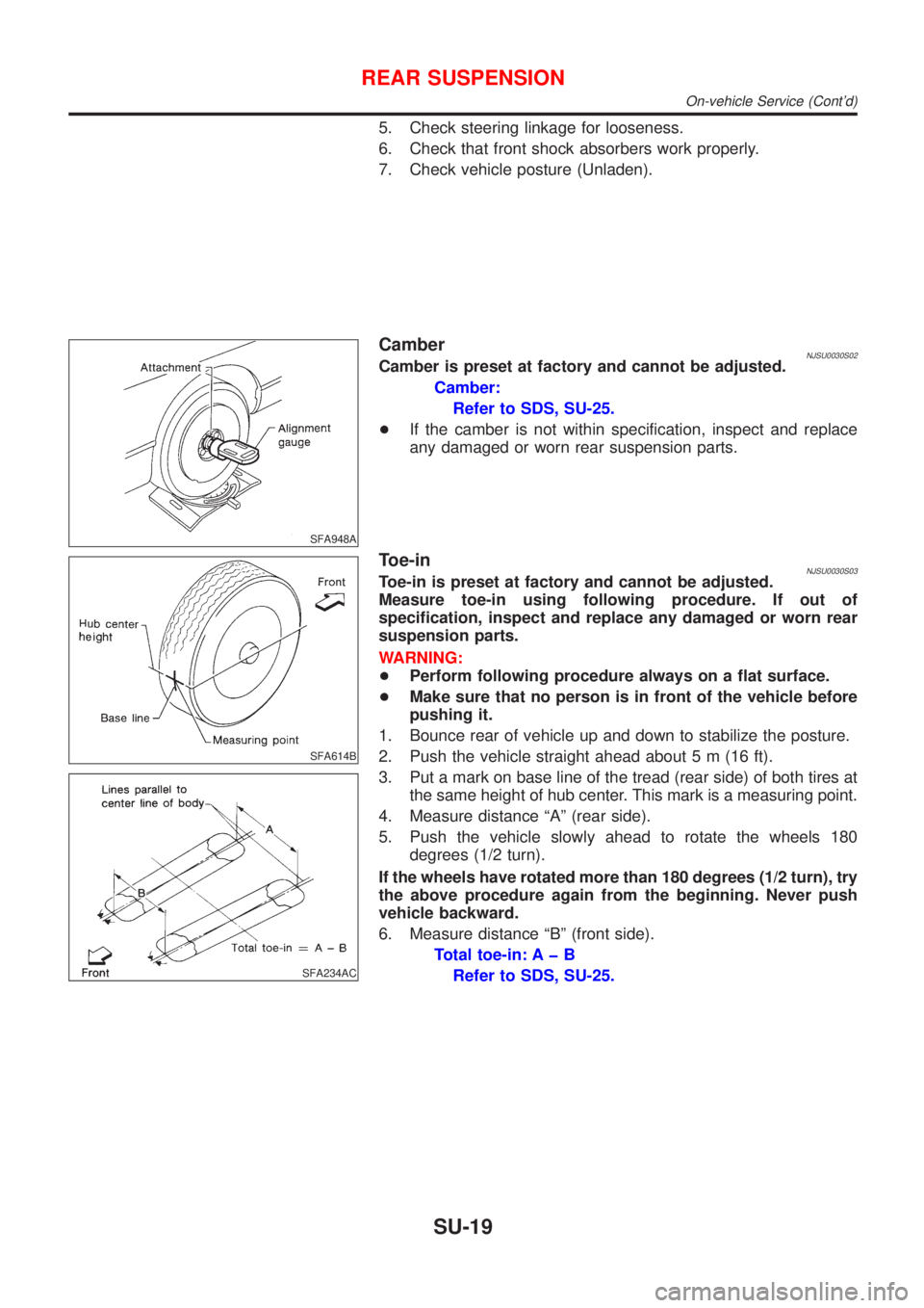
CamberNJSU0030S02Camber is preset at factory and cannot be adjusted.
Camber:
Refer to SDS, SU-25.
+If the camber is not within specification, inspect and replace
any damaged or worn rear suspension parts.
SFA614B
SFA234AC
Toe-inNJSU0030S03Toe-in is preset at factory and cannot be adjusted.
Measure toe-in using following procedure. If out of
specification, inspect and replace any damaged or worn rear
suspension parts.
WARNING:
+Perform following procedure always on a flat surface.
+Make sure that no person is in front of the vehicle before
pushing it.
1. Bounce rear of vehicle up and down to stabilize the posture.
2. Push the vehicle straight ahead about 5 m (16 ft).
3. Put a mark on base line of the tread (rear side) of both tires at
the same height of hub center. This mark is a measuring point.
4. Measure distance ªAº (rear side).
5. Push the vehicle slowly ahead to rotate the wheels 180
degrees (1/2 turn).
If the wheels have rotated more than 180 degrees (1/2 turn), try
the above procedure again from the beginning. Never push
vehicle backward.
6. Measure distance ªBº (front side).
Total toe-in: A þ B
Refer to SDS, SU-25.
REAR SUSPENSION
On-vehicle Service (Cont'd)
SU-19