2001 NISSAN ALMERA N16 warning
[x] Cancel search: warningPage 632 of 2493

SEF621WA
SEF646X
SEC163BA
Overall Function CheckNJEC0489Use this procedure to check the overall function of the cooling fan.
During this check, a DTC might not be confirmed.
WARNING:
Never remove the radiator cap when the engine is hot. Serious
burns could be caused by high pressure fluid escaping from
the radiator.
Wrap a thick cloth around cap. Carefully remove the cap by
turning it a quarter turn to allow built-up pressure to escape.
Then turn the cap all the way off.
With CONSULT-II
1) Check the coolant level and mixture ratio (using coolant tester)
in the reservoir tank and radiator.
Allow engine to cool before checking coolant level and
mixture ratio.
+If the coolant level in the reservoir tank and/or radiator is below
the proper range, skip the following steps and go to ªDiagnos-
tic Procedureº, EC-339.
+If the coolant mixture ratio is out of the range of 45 to 55%,
replace the coolant in the following procedure LC-17, ªChang-
ing Engine Coolantº.
2) Confirm whether customer filled the coolant or not. If customer
filled the coolant, skip the following steps and go to ªDiagnos-
tic Procedureº, EC-339.
3) Turn ignition switch ªONº.
4) Perform ªCOOLING FANº in ªACTIVE TESTº mode with CON-
SULT-II.
5) If the results are NG, go to ªDiagnostic Procedureº, EC-339.
Without CONSULT-II
1) Check the coolant level and mixture ratio (using coolant tester)
in the reservoir tank and radiator.
Allow engine to cool before checking coolant level and
mixture ratio.
+If the coolant level in the reservoir tank and/or radiator is below
the proper range, skip the following steps and go to ªDiagnos-
tic Procedureº, EC-339.
+If the coolant mixture ratio is out of the range of 45 to 55%,
replace the coolant in the following procedure LC-17, ªChang-
ing Engine Coolantº.
2) Confirm whether customer filled the coolant or not. If customer
filled the coolant, skip the following steps and go to ªDiagnos-
tic Procedureº, EC-339.
3) Start engine.
Be careful not to overheat engine.
4) Set temperature control lever to full cold position.
5) Turn air conditioner switch ªONº.
6) Turn blower fan switch ªONº.
7) Run engine at idle for a few minutes with air conditioner oper-
ating.
Be careful not to overheat engine.
8) Make sure that cooling fan operates. Refer to ªOPERATIONº
table for cooling fan, EC-334.
If NG, go to ªDiagnostic Procedureº, EC-339.
DTC P1217 OVERHEAT (COOLING SYSTEM)QG
On Board Diagnosis Logic (Cont'd)
EC-336
Page 790 of 2493

Supplemental Restraint System (SRS) ªAIR
BAGº and ªSEAT BELT PRE-TENSIONERº
NJEC0601The Supplemental Restraint System such as ªAIR BAGº and ªSEAT BELT PRE-TENSIONERº used along with
a seat belt, helps to reduce the risk or severity of injury to the driver and front passenger for certain types of
collision. The SRS system composition which is available to NISSAN MODEL N16 is as follows (The compo-
sition varies according to the destination and optional equipment.):
+For a frontal collision
The Supplemental Restraint System consists of driver air bag module (located in the center of the steer-
ing wheel), front passenger air bag module (located on the instrument panel on passenger side), front seat
belt pre-tensioners, a diagnosis sensor unit, warning lamp, wiring harness and spiral cable.
+For a side collision
The Supplemental Restraint System consists of front side air bag module (located in the outer side of front
seat), side air bag (satellite) sensor, diagnosis sensor unit (one of components of air bags for a frontal
collision), wiring harness, warning lamp (one of components of air bags for a frontal collision).
Information necessary to service the system safely is included in theRS sectionof this Service Manual.
WARNING:
+To avoid rendering the SRS inoperative, which could increase the risk of personal injury or death
in the event of a collision which would result in air bag inflation, all maintenance should be per-
formed by an authorized NISSAN dealer.
+Improper maintenance, including incorrect removal and installation of the SRS, can lead to per-
sonal injury caused by unintentional activation of the system. For removal of Spiral Cable and Air
Bag Module, see the RS section.
+Do not use electrical test equipment on any circuit related to the SRS unless instructed to in this
Service Manual. SRS wiring harness can be identified by yellow harness connector.
PRECAUTIONSYD
Supplemental Restraint System (SRS) ªAIR BAGº and ªSEAT BELT PRE-TENSIONERº
EC-494
Page 807 of 2493
JEF344Y
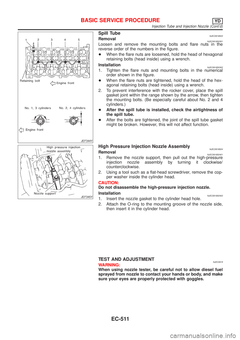
Spill TubeNJEC0618S03RemovalNJEC0618S0301Loosen and remove the mounting bolts and flare nuts in the
reverse order of the numbers in the figure.
+When the flare nuts are loosened, hold the head of hexagonal
retaining bolts (head inside) using a wrench.
Installation
NJEC0618S03021. Tighten the flare nuts and mounting bolts in the numerical
order shown in the figure.
+When the flare nuts are tightened, hold the head of the hex-
agonal retaining bolts (head inside) using a wrench.
2. To prevent interference with the rocker cover, place the spill
gasket joint within the range shown by the arrow, then tighten
the mounting bolts. (Be especially careful about No. 2 and 4
cylinders.)
+After the spill tube is installed, check the airtightness of
the spill tube.
+After the bolts are tightened, the joint of the spill tube gasket
might be broken. However, this will not affect function.
JEF345Y
High Pressure Injection Nozzle AssemblyNJEC0618S04RemovalNJEC0618S04011. Remove the nozzle support, then pull out the high-pressure
injection nozzle assembly by turning it clockwise/
counterclockwise.
2. Using a tool such as a flat-head screwdriver, remove the cop-
per washer inside the cylinder head.
CAUTION:
Do not disassemble the high-pressure injection nozzle.
Installation
NJEC0618S04021. Insert the nozzle gasket to the cylinder head hole.
2. Attach the O-ring to the mounting groove of the nozzle side,
then insert it in the cylinder head.
TEST AND ADJUSTMENTNJEC0619WARNING:
When using nozzle tester, be careful not to allow diesel fuel
sprayed from nozzle to contact your hands or body, and make
sure your eyes are properly protected with goggles.
BASIC SERVICE PROCEDUREYD
Injection Tube and Injection Nozzle (Cont'd)
EC-511
Page 816 of 2493
Fuel Filter
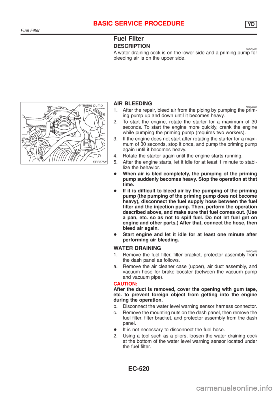
DESCRIPTIONNJEC0623A water draining cock is on the lower side and a priming pump for
bleeding air is on the upper side.
SEF375Y
AIR BLEEDINGNJEC06241. After the repair, bleed air from the piping by pumping the prim-
ing pump up and down until it becomes heavy.
2. To start the engine, rotate the starter for a maximum of 30
seconds. To start the engine more quickly, crank the engine
while pumping the priming pump (requires two workers).
3. If the engine does not start after rotating the starter for a maxi-
mum of 30 seconds, stop it once, and pump the priming pump
again until it becomes heavy.
4. Rotate the starter again until the engine starts running.
5. After the engine starts, let it idle for at least 1 minute to stabi-
lize the behavior.
+When air is bled completely, the pumping of the priming
pump suddenly becomes heavy. Stop the operation at that
time.
+If it is difficult to bleed air by the pumping of the priming
pump (the pumping of the priming pump does not become
heavy), disconnect the fuel supply hose between the fuel
filter and the injection pump. Then, perform the operation
described above, and make sure that fuel comes out. (Use
a pan, etc. so as not to spill fuel. Do not let fuel get on
engine and other parts.) After that, connect the hose, then
bleed air again.
+Start engine and let it idle for at least one minute after
performing air bleeding.
WATER DRAININGNJEC06251. Remove the fuel filter, filter bracket, protector assembly from
the dash panel as follows.
a. Remove the air cleaner case (upper), air duct assembly, and
vacuum hose for brake booster (between the vacuum pump
and vacuum pipe).
CAUTION:
After the duct is removed, cover the opening with gum tape,
etc. to prevent foreign object from getting into the engine
during the operation.
b. Disconnect the water level warning sensor harness connector.
c. Remove the mounting nuts on the dash panel, then remove the
fuel filter, filter bracket, and protector assembly from the dash
panel.
+It is not necessary to disconnect the fuel hose.
2. Using a tool such as a pliers, loosen the water draining cock
at the bottom of the water level warning sensor located under
the fuel filter.
BASIC SERVICE PROCEDUREYD
Fuel Filter
EC-520
Page 819 of 2493
+Erasing the emission-related diagnostic information using CONSULT-II is easier and quicker than
switching the diagnostic test mode using the data link connector.
Malfunction Indicator (MI)
DESCRIPTIONNJEC0628
SAT652J
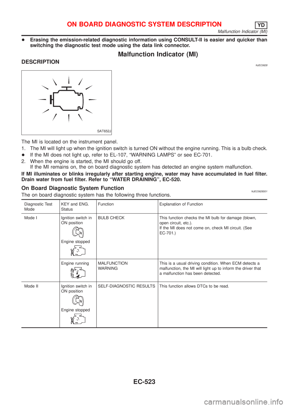
The MI is located on the instrument panel.
1. The MI will light up when the ignition switch is turned ON without the engine running. This is a bulb check.
+If the MI does not light up, refer to EL-107, ªWARNING LAMPSº or see EC-701.
2. When the engine is started, the MI should go off.
If the MI remains on, the on board diagnostic system has detected an engine system malfunction.
If MI illuminates or blinks irregularly after starting engine, water may have accumulated in fuel filter.
Drain water from fuel filter. Refer to ªWATER DRAININGº, EC-520.
On Board Diagnostic System FunctionNJEC0628S01The on board diagnostic system has the following three functions.
Diagnostic Test
ModeKEY and ENG.
StatusFunction Explanation of Function
Mode I Ignition switch in
ON position
Engine stopped
BULB CHECK This function checks the MI bulb for damage (blown,
open circuit, etc.).
If the MI does not come on, check MI circuit. (See
EC-701.)
Engine running
MALFUNCTION
WARNINGThis is a usual driving condition. When ECM detects a
malfunction, the MI will light up to inform the driver that
a malfunction has been detected.
Mode II Ignition switch in
ON position
Engine stopped
SELF-DIAGNOSTIC RESULTS This function allows DTCs to be read.
ON BOARD DIAGNOSTIC SYSTEM DESCRIPTIONYD
Malfunction Indicator (MI)
EC-523
Page 821 of 2493
Diagnostic Test Mode I Ð Bulb CheckNJEC0628S03In this mode, the MI on the instrument panel should stay ON. If it remains OFF, check the bulb. Refer to EL-107,
ªWARNING LAMPSº or see EC-701.
Diagnostic Test Mode I Ð Malfunction WarningNJEC0628S04
MI Condition
ON When the malfunction is detected or the ECM's CPU is malfunctioning.
OFF No malfunction.
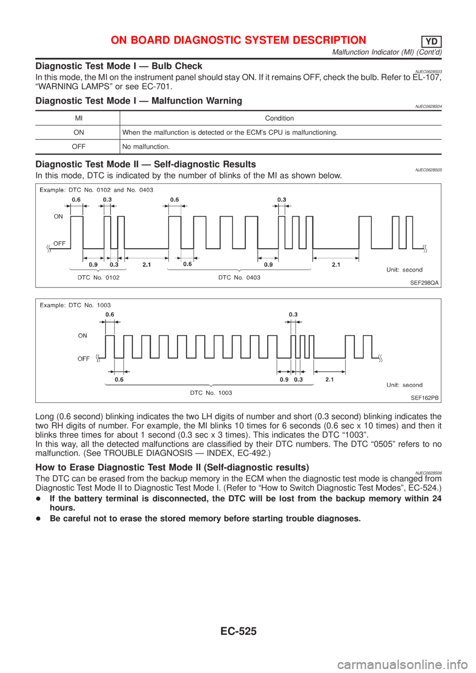
Diagnostic Test Mode II Ð Self-diagnostic ResultsNJEC0628S05In this mode, DTC is indicated by the number of blinks of the MI as shown below.
SEF298QA
SEF162PB
Long (0.6 second) blinking indicates the two LH digits of number and short (0.3 second) blinking indicates the
two RH digits of number. For example, the MI blinks 10 times for 6 seconds (0.6 sec x 10 times) and then it
blinks three times for about 1 second (0.3 sec x 3 times). This indicates the DTC ª1003º.
In this way, all the detected malfunctions are classified by their DTC numbers. The DTC ª0505º refers to no
malfunction. (See TROUBLE DIAGNOSIS Ð INDEX, EC-492.)
How to Erase Diagnostic Test Mode II (Self-diagnostic results)NJEC0628S06The DTC can be erased from the backup memory in the ECM when the diagnostic test mode is changed from
Diagnostic Test Mode II to Diagnostic Test Mode I. (Refer to ªHow to Switch Diagnostic Test Modesº, EC-524.)
+If the battery terminal is disconnected, the DTC will be lost from the backup memory within 24
hours.
+Be careful not to erase the stored memory before starting trouble diagnoses.
ON BOARD DIAGNOSTIC SYSTEM DESCRIPTIONYD
Malfunction Indicator (MI) (Cont'd)
EC-525
Page 916 of 2493

AEC640
SEF111X
SEC163BA
MEC475B
Overall Function CheckNJEC0664Use this procedure to check the overall function of the cooling fan.
During this check, a DTC might not be confirmed.
WARNING:
Never remove the radiator cap when the engine is hot. Serious
burns could be caused by high pressure fluid escaping from
the radiator.
Wrap a thick cloth around the cap. Carefully remove the cap
by turning it a quarter turn to allow built-up pressure to
escape. Then turn the cap all the way off.
WITH CONSULT-IINJEC0664S011) Check the coolant level in the reservoir tank and radiator.
Allow engine to cool before checking coolant level.
If the coolant level in the reservoir tank and/or radiator is below
the proper range, skip the following steps and go to ªDiagnos-
tic Procedureº, EC-622.
2) Confirm whether customer filled the coolant or not. If customer
filled the coolant, skip the following steps and go to ªDiagnos-
tic Procedureº, EC-622.
3) Turn ignition switch ªONº.
4) Perform ªCOOLING FANº in ªACTIVE TESTº mode with CON-
SULT-II and make sure that cooling fans operate when touch-
ing ªHIGHº or ªLOWº.
If NG, go to ªDiagnostic Procedureº, EC-622.
WITHOUT CONSULT-IINJEC0664S021) Check the coolant level in the reservoir tank and radiator.
Allow engine to cool before checking coolant level.
If the coolant level in the reservoir tank and/or radiator is below
the proper range, skip the following steps and go to ªDiagnos-
tic Procedureº, EC-622.
2) Confirm whether customer filled the coolant or not. If customer
filled the coolant, skip the following steps and go to ªDiagnos-
tic Procedureº, EC-622.
3) Start engine.
Be careful not to overheat engine.
4) Set temperature control lever to full cold position.
5) Turn air conditioner switch ªONº.
6) Turn blower fan switch ªONº.
7) Run engine at idle for a few minutes with air conditioner oper-
ating.
Be careful not to overheat engine.
8) Make sure that cooling fans operate at low speed.
9) Turn ignition switch ªOFFº.
10) Turn air conditioner switch and blower fan switch ªOFFº.
11) Disconnect engine coolant temperature sensor harness con-
nector.
12) Connect 150Wresistor to engine coolant temperature sensor
harness connector.
13) Start engine and make sure that cooling fans operate at higher
speed than low speed.
Be careful not to overheat engine.
14) If NG, go to ªDiagnostic Procedureº, EC-622.
DTC P1217 OVER HEATYD
On Board Diagnosis Logic (Cont'd)
EC-620
Page 1003 of 2493
SMA803A
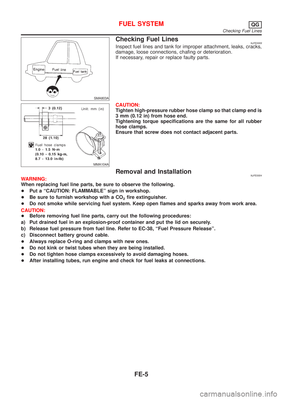
Checking Fuel LinesNJFE0009Inspect fuel lines and tank for improper attachment, leaks, cracks,
damage, loose connections, chafing or deterioration.
If necessary, repair or replace faulty parts.
MMA104A
CAUTION:
Tighten high-pressure rubber hose clamp so that clamp end is
3 mm (0.12 in) from hose end.
Tightening torque specifications are the same for all rubber
hose clamps.
Ensure that screw does not contact adjacent parts.
Removal and InstallationNJFE0004WARNING:
When replacing fuel line parts, be sure to observe the following.
+Put a ªCAUTION: FLAMMABLEº sign in workshop.
+Be sure to furnish workshop with a CO
2fire extinguisher.
+Do not smoke while servicing fuel system. Keep open flames and sparks away from work area.
CAUTION:
+Before removing fuel line parts, carry out the following procedures:
a) Put drained fuel in an explosion-proof container and put the lid on securely.
b) Release fuel pressure from fuel line. Refer to EC-38, ªFuel Pressure Releaseº.
c) Disconnect battery ground cable.
+Always replace O-ring and clamps with new ones.
+Do not kink or twist tubes when they are being installed.
+Do not tighten hose clamps excessively to avoid damaging hoses.
+After installing tubes, run engine and check for fuel leaks at connections.
FUEL SYSTEMQG
Checking Fuel Lines
FE-5