Page 641 of 2493

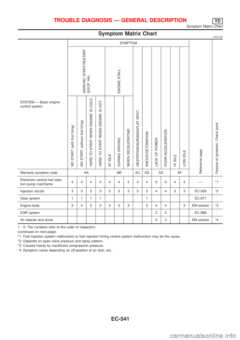
Main 12 Causes of Overheating=NJEC0492
Engine Step Inspection item Equipment Standard Reference page
OFF 1+Blocked radiator
+Blocked condenser
+Blocked radiator grille
+Blocked bumper+Visual No blocking Ð
2+Coolant mixture+Coolant tester 50 - 50% coolant mixture See MA-20, ªRECOM-
MENDED FLUIDS AND
LUBRICANTSº.
3+Coolant level+Visual Coolant up to MAX level
in reservoir tank and
radiator filler neckSee LC-17, ªChanging
Engine Coolantº.
4+Radiator cap+Pressure tester 59 - 98 kPa
(0.59 - 0.98 bar, 0.6 - 1.0
kg/cm
2,9-14psi) (Limit)See LC-10, ªSystem
Checkº.
ON*
25+Coolant leaks+Visual No leaks See LC-10, ªSystem
Checkº.
ON*
26+Thermostat+Touch the upper and
lower radiator hosesBoth hoses should be
hotSee LC-15, ªThermostatº
and LC-16, ªRadiatorº.
ON*
17+Cooling fan+CONSULT-II Operating See ªTROUBLE DIAG-
NOSIS FOR OVER-
HEATº (EC-334).
OFF 8+Combustion gas leak+Color checker chemi-
cal tester 4 Gas ana-
lyzerNegative Ð
ON*
39+Coolant temperature
gauge+Visual Gauge less than 3/4
when drivingÐ
+Coolant overflow to
reservoir tank+Visual No overflow during driv-
ing and idlingSee LC-17, ªChanging
Engine Coolantº.
OFF*
410+Coolant return from
reservoir tank to radia-
tor+Visual Should be initial level in
reservoir tankSee LC-18, ªRefilling
Engine Coolantº.
OFF 11+Cylinder head+Straight gauge feeler
gauge0.1 mm (0.004 in) Maxi-
mum distortion (warping)See EM-36, ªInspectionº,
ªCYLINDER HEADº.
12+Cylinder block and
pistons+Visual No scuffing on cylinder
walls or pistonSee EM-54, ªInspectionº,
ªCYLINDER BLOCKº.
*1: Turn the ignition switch ON.
*2: Engine running at 3,000 rpm for 10 minutes.
*3: Drive at 90 km/h (55 MPH) for 30 minutes and then let idle for 10 minutes.
*4: After 60 minutes of cool down time.
For more information, refer to LC-23, ª OVERHEATING CAUSE ANALYSISº.
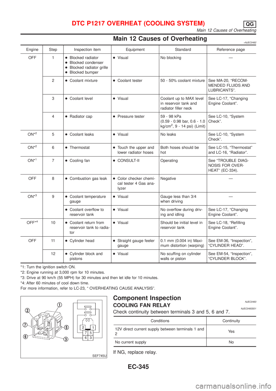
SEF745U
Component InspectionNJEC0493COOLING FAN RELAYNJEC0493S01Check continuity between terminals 3 and 5, 6 and 7.
Conditions Continuity
12V direct current supply between terminals 1 and
2Ye s
No current supply No
If NG, replace relay.
DTC P1217 OVERHEAT (COOLING SYSTEM)QG
Main 12 Causes of Overheating
EC-345
Page 788 of 2493

Alphabetical & P No. Index for DTCNJEC0600ALPHABETICAL INDEX FOR DTCNJEC0600S01X: Applicable Ð: Not applicable
Items
(CONSULT-II screen terms)DTC
MI illumination Reference page
CONSULT-II ECM
ACCEL POS SENSOR P0120 0403 X EC-577
BATTERY VOLTAGE P1660 0502 Ð EC-672
BRAKE SW P0571 0807 X EC-597
COOLANT TEMP SEN P0115 0103 X EC-572
CRANK POS SEN (TDC) P0335 0407 X EC-587
ECM RLY P1620 0902 X EC-666
ECM 2 P1607 0301 X EC-664
ECM 10 P1107 0802 X EC-604
ECM 12 P1603 0901 X EC-664
ECM 15 P1621 0903 Ð EC-670
FUEL CUT SYSTEM2 P1202 1002 X EC-612
MASS AIR FLOW SEN P0100 0102 X EC-566
NO DTC IS DETECTED.
FURTHER TESTING
MAY BE REQUIRED.P0000 0505ÐÐ
OVER HEAT P1217 0208 X EC-618
P1´CAM POS SEN P1341 0701 X EC-652
P2´TDC PULSE SIG P1337 0702 X EC-646
P3´PUMP COMM LINE P1600 0703 X EC-658
P4´SPILL/V CIRC P1251 0704 X EC-640
P5´PUMP C/MODULE P1690 0705 X EC-674
P7´F/INJ TIMG FB P1241 0707 X EC-634
P9´FUEL TEMP SEN P1180 0402 X EC-606
VEHICLE SPEED SEN P0500 0104 X EC-593
TROUBLE DIAGNOSIS Ð INDEXYD
Alphabetical & P No. Index for DTC
EC-492
Page 789 of 2493

P NO. INDEX FOR DTC=NJEC0600S02X: Applicable Ð: Not applicable
DTC
MI illuminationItems
(CONSULT-II screen terms)Reference page
CONSULT-II ECM
P0000 0505ÐNO DTC IS DETECTED.
FURTHER TESTING
MAY BE REQUIRED.Ð
P0100 0102 X MASS AIR FLOW SEN EC-566
P0115 0103 X COOLANT TEMP SEN EC-572
P0120 0403 X ACCEL POS SENSOR EC-577
P0335 0407 X CRANK POS SEN (TDC) EC-587
P0500 0104 X VEHICLE SPEED SEN EC-593
P0571 0807 X BRAKE SW EC-597
P1107 0802 X ECM 10 EC-604
P1180 0402 X P9´FUEL TEMP SEN EC-606
P1202 1002 X FUEL CUT SYSTEM2 EC-612
P1217 0208 X OVER HEAT EC-618
P1241 0707 X P7´F/INJ TIMG FB EC-634
P1251 0704 X P4´SPILL/V CIRC EC-640
P1337 0702 X P2´TDC PULSE SIG EC-646
P1341 0701 X P1´CAM POS SEN EC-652
P1600 0703 X P3´PUMP COMM LINE EC-658
P1603 0901 X ECM 12 EC-664
P1607 0301 X ECM 2 EC-664
P1620 0902 X ECM RLY EC-666
P1621 0903 Ð ECM 15 EC-670
P1660 0502 Ð BATTERY VOLTAGE EC-672
P1690 0705 X P5´PUMP C/MODULE EC-674
TROUBLE DIAGNOSIS Ð INDEXYD
Alphabetical & P No. Index for DTC (Cont'd)
EC-493
Page 828 of 2493

SEF858S
SEF233G
SEF234G
IntroductionNJEC0630The engine has an ECM to control major systems such as fuel
injection control, fuel injection timing control, glow control system,
etc. The ECM accepts input signals from sensors and instantly
drives electronic control fuel injection pump. It is essential that both
input and output signals are proper and stable. At the same time,
it is important that there are no problems such as vacuum leaks,
or other problems with the engine.
It is much more difficult to diagnose a problem that occurs intermit-
tently rather than continuously. Most intermittent problems are
caused by poor electric connections or improper wiring. In this
case, careful checking of suspected circuits may help prevent the
replacement of good parts.
A visual check only may not find the cause of the problems. A road
test with CONSULT-II or a circuit tester connected should be per-
formed. Follow the ªWork Flowº, EC-534.
Before undertaking actual checks, take a few minutes to talk with
a customer who approaches with a driveability complaint. The cus-
tomer can supply good information about such problems, espe-
cially intermittent ones. Find out what symptoms are present and
under what conditions they occur. A ªDiagnostic Worksheetº like the
example on next page should be used.
Start your diagnosis by looking for ªconventionalº problems first.
This will help troubleshoot driveability problems on an electronically
controlled engine vehicle.
SEF907L
DIAGNOSTIC WORKSHEETNJEC0630S01There are many operating conditions that lead to the malfunction
of engine components. A good grasp of such conditions can make
troubleshooting faster and more accurate.
In general, each customer feels differently about a problem. It is
important to fully understand the symptoms or conditions for a
customer complaint.
Utilize a diagnostic worksheet like the one shown below in order to
organize all the information for troubleshooting.
TROUBLE DIAGNOSIS Ð INTRODUCTIONYD
EC-532
Page 837 of 2493

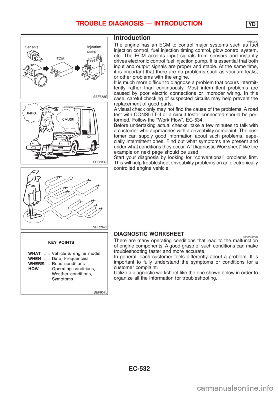
Symptom Matrix ChartNJEC1257
SYSTEM Ð Basic engine
control systemSYMPTOM
Reference page
Feature of symptom, Check pointHARD/NO START/RESTART
(EXCP. HA)
ENGINE STALL
HESITATION/SURGING/FLAT SPOT
KNOCK/DETONATION
LACK OF POWER
POOR ACCELERATION
HI IDLE
LOW IDLE NO START (with first firing)
NO START (without first firing)
HARD TO START WHEN ENGINE IS COLD
HARD TO START WHEN ENGINE IS HOT
AT IDLE
DURING DRIVING
WHEN DECELERATINGWarranty symptom code AA AB AC AD AE AF
Electronic control fuel injec-
tion pump mainframe4444444445544 Ð *1
Injection nozzle3333333334433EC-509 *2
Glow system1111 1EC-677
Engine body3333333 344 3EMsection *3
EGR system3 3 EC-686
Air cleaner and ducts 3 3 MA section *4
1 - 5: The numbers refer to the order of inspection.
(continued on next page)
*1: Fuel injection system malfunction or fuel injection timing control system malfunction may be the cause.
*2: Depends on open-valve pressure and spray pattern.
*3: Caused mainly by insufficient compression pressure.
*4: Symptom varies depending on off-position of air duct, etc.
TROUBLE DIAGNOSIS Ð GENERAL DESCRIPTIONYD
Symptom Matrix Chart
EC-541
Page 838 of 2493

SYSTEM Ð Basic engine control
systemSYMPTOM
Reference page
Feature of symptom, Check pointROUGH IDLE/HUNTING
IDLING VIBRATION
SLOW/NO RETURN TO IDLE
OVERHEAT/HIGH ENGINE COOLANT TEMPERATURE
EXCESSIVE FUEL CONSUMPTION
EXCESSIVE OIL CONSUMPTION
ABNORMAL SMOKE COLOR
DEAD BATTERY (UNDER CHARGE)
Malfunction indicator illuminates.
Can be detected by CONSULT-II?BLACK SMOKE
WHITE SMOKEWarranty symptom code AG AH AJ AK AL AM AP HA
Electronic control fuel injection
pump mainframe44345433Ð*1
Injection nozzle 3 3 3 4 3 EC-509 *2
Glow system 1 1 EC-677
Engine body 3 3 3 3 3 3 EM section *3
EGR system 3 EC-686
Air cleaner and ducts 3 3 MA section *4
1 - 5: The numbers refer to the order of inspection.
(continued on next page)
*1: Fuel injection system malfunction or fuel injection timing control system malfunction may be the cause.
*2: Depends on open-valve pressure and spray pattern.
*3: Caused mainly by insufficient compression pressure.
*4: Symptom varies depending on off-position of air duct, etc.
TROUBLE DIAGNOSIS Ð GENERAL DESCRIPTIONYD
Symptom Matrix Chart (Cont'd)
EC-542
Page 839 of 2493
SYSTEM Ð ENGINE CONTROL system
Malfunction
SYMPTOM
Reference page
Feature of symptom, Check pointHARD/NO START/RESTART
(EXCP. HA)
ENGINE STALL
HESITATION/SURGING/FLAT SPOT
KNOCK/DETONATION
LACK OF POWER
POOR ACCELERATION
HI IDLE
LOW IDLE NO START (with first firing)
NO START (without first firing)
HARD TO START WHEN ENGINE IS COLD
HARD TO START WHEN ENGINE IS HOT
AT IDLE
DURING DRIVING
WHEN DECELERATINGWarranty symptom code AA AB AC AD AE AF
ENGINE CONTROL
Electronic control fuel injection
pump circuit*a, *b 1 1
111111111
Ð
*c, *d
Mass air flow sensor circuit*a, *c
111
EC-566
*b
Engine coolant temperature sensor
circuit*a, *b 1 1 1 1 EC-572 *1
Vehicle speed sensor circuit *a, *b 1 EC-593
1 - 5: The numbers refer to the order of inspection.
(continued on next page)
*a: Open
*b: Short
*c: Ground short
*d: Noise
*1: Compensation according to engine coolant temperature does not function.
TROUBLE DIAGNOSIS Ð GENERAL DESCRIPTIONYD
Symptom Matrix Chart (Cont'd)
EC-543
Page 840 of 2493
SYSTEM Ð ENGINE CONTROL system
Malfunction
SYMPTOM
Reference page
Feature of symptom, Check pointROUGH IDLE/HUNTING
IDLING VIBRATION
SLOW/NO RETURN TO IDLE
OVERHEAT/HIGH ENGINE COOLANT TEMPERATURE
EXCESSIVE FUEL CONSUMPTION
EXCESSIVE OIL CONSUMPTION
ABNORMAL SMOKE COLOR
DEAD BATTERY (UNDER CHARGE)
Malfunction indicator illuminates.
Can be detected by CONSULT-II?BLACK SMOKE
WHITE SMOKEWarranty symptom code AG AH AJ AK AL AM AP HA
ENGINE CONTROL
Electronic control fuel injection pump
circuit*a, *b 1 1 1
11 Ð
*c, *d 1
Mass air flow sensor circuit*a, *c
1 EC-566
*b 1
Engine coolant temperature sensor cir-
cuit*a, *b 1 1 1 1 1 EC-572 *1
Vehicle speed sensor circuit *a, *b 1 EC-593
1 - 5: The numbers refer to the order of inspection.
(continued on next page)
*a: Open
*b: Short
*c: Ground short
*d: Noise
*1: Compensation according to engine coolant temperature does not function.
TROUBLE DIAGNOSIS Ð GENERAL DESCRIPTIONYD
Symptom Matrix Chart (Cont'd)
EC-544