2001 NISSAN ALMERA N16 EL page 71
[x] Cancel search: EL page 71Page 310 of 2493

Items
(CONSULT-II screen terms)DTC*6
Reference page
CONSULT-II
GST*2ECM*1
COOLANT T SEN/CIRC*3 P0115 0115 EC-163
ENG OVER TEMP P1217 1217 EC-334
HO2S1 (B1) P0130 0130 EC-176
KNOCK SEN/CIRC-B1 P0325 0325 EC-268
MAF SEN/CIRCUIT*3 P0100 0100 EC-152
NATS MALFUNCTION P1610 - P1615 1610 - 1615 EL-239
NO DTC IS DETECTED.
FURTHER TESTING MAYBE REQUIREDÐ 0000 Ð
NO DTC IS DETECTED.
FURTHER TESTING MAYBE REQUIREDÐ Flashing*5 EC-73
THRTL POS SEN/CIRC*3 P0120 0120 EC-168
VEH SPEED SEN/CIRC*4 P0500 0500 EC-309
*1: In Diagnostic Test Mode II (Self-diagnostic results) (If so equipped). These numbers are controlled by NISSAN.
*2: These numbers are prescribed by ISO 15031-6.
*3: When the fail-safe operation occurs, the MI illuminates.
*4: The MI illuminates when the ªRevolution sensor signalº and the ªVehicle speed sensor signalº meet the fail-safe condition at the
same time.
*5: While engine is running.
*6: 1st trip DTC No. is the same as DTC No.
P No. Index for DTCNJEC0001S0402
DTC*6
Items
(CONSULT-II screen terms)Reference page
CONSULT-II
GST*2ECM*1
Ð Ð Unable to access ECM EC-123
Ð Flashing*5NO DTC IS DETECTED.
FURTHER TESTING MAYBE REQUIRED.EC-73
Ð 0000NO DTC IS DETECTED.
FURTHER TESTING MAYBE REQUIRED.Ð
P0100 0100 MAF SEN/CIRCUIT*3 EC-152
P0115 0115 COOLANT T SEN/CIRC*3 EC-163
P0120 0120 THRTL POS SEN/CIRC*3 EC-168
P0130 0130 HO2S1 (B1) EC-176
P0325 0325 KNOCK SEN/CIRC-B1 EC-268
P0335 0335 CKP SEN/CIRCUIT EC-272
P0340 0340 CMP SEN/CIRCUIT EC-278
P0500 0500 VEH SPEED SEN/CIRC*4 EC-309
P1217 1217 ENG OVER TEMP EC-334
P1610 - 1615 1610 - 1615 NATS MALFUNCTION EL-239
*1: In Diagnostic Test Mode II (Self-diagnostic results) (If so equipped). These numbers are controlled by NISSAN.
*2: These numbers are prescribed by ISO 15031-6
*3: When the fail-safe operation occurs, the MI illuminates.
TROUBLE DIAGNOSIS Ð INDEXQG
Alphabetical & P No. Index for DTC (Cont'd)
EC-14
Page 330 of 2493
EVAP canister purge volume control solenoid valve is controlled by ECM. When the engine operates, the flow
rate of vapor controlled by EVAP canister purge volume control solenoid valve is proportionally regulated as
the air flow increases.
EVAP canister purge volume control solenoid valve also shuts off the vapor purge line during decelerating and
idling.
SEF917W
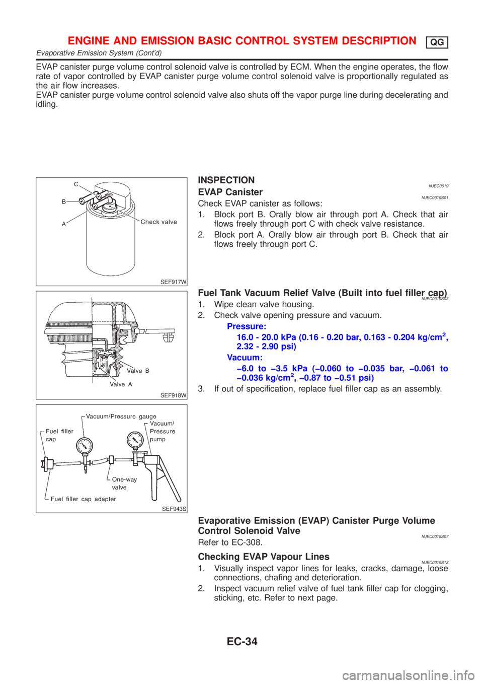
INSPECTIONNJEC0019EVAP CanisterNJEC0019S01Check EVAP canister as follows:
1. Block port B. Orally blow air through port A. Check that air
flows freely through port C with check valve resistance.
2. Block port A. Orally blow air through port B. Check that air
flows freely through port C.
SEF918W
SEF943S
Fuel Tank Vacuum Relief Valve (Built into fuel filler cap)NJEC0019S031. Wipe clean valve housing.
2. Check valve opening pressure and vacuum.
Pressure:
16.0 - 20.0 kPa (0.16 - 0.20 bar, 0.163 - 0.204 kg/cm
2,
2.32 - 2.90 psi)
Vacuum:
þ6.0 to þ3.5 kPa (þ0.060 to þ0.035 bar, þ0.061 to
þ0.036 kg/cm
2, þ0.87 to þ0.51 psi)
3. If out of specification, replace fuel filler cap as an assembly.
Evaporative Emission (EVAP) Canister Purge Volume
Control Solenoid Valve
NJEC0019S07Refer to EC-308.
Checking EVAP Vapour LinesNJEC0019S131. Visually inspect vapor lines for leaks, cracks, damage, loose
connections, chafing and deterioration.
2. Inspect vacuum relief valve of fuel tank filler cap for clogging,
sticking, etc. Refer to next page.
ENGINE AND EMISSION BASIC CONTROL SYSTEM DESCRIPTIONQG
Evaporative Emission System (Cont'd)
EC-34
Page 354 of 2493
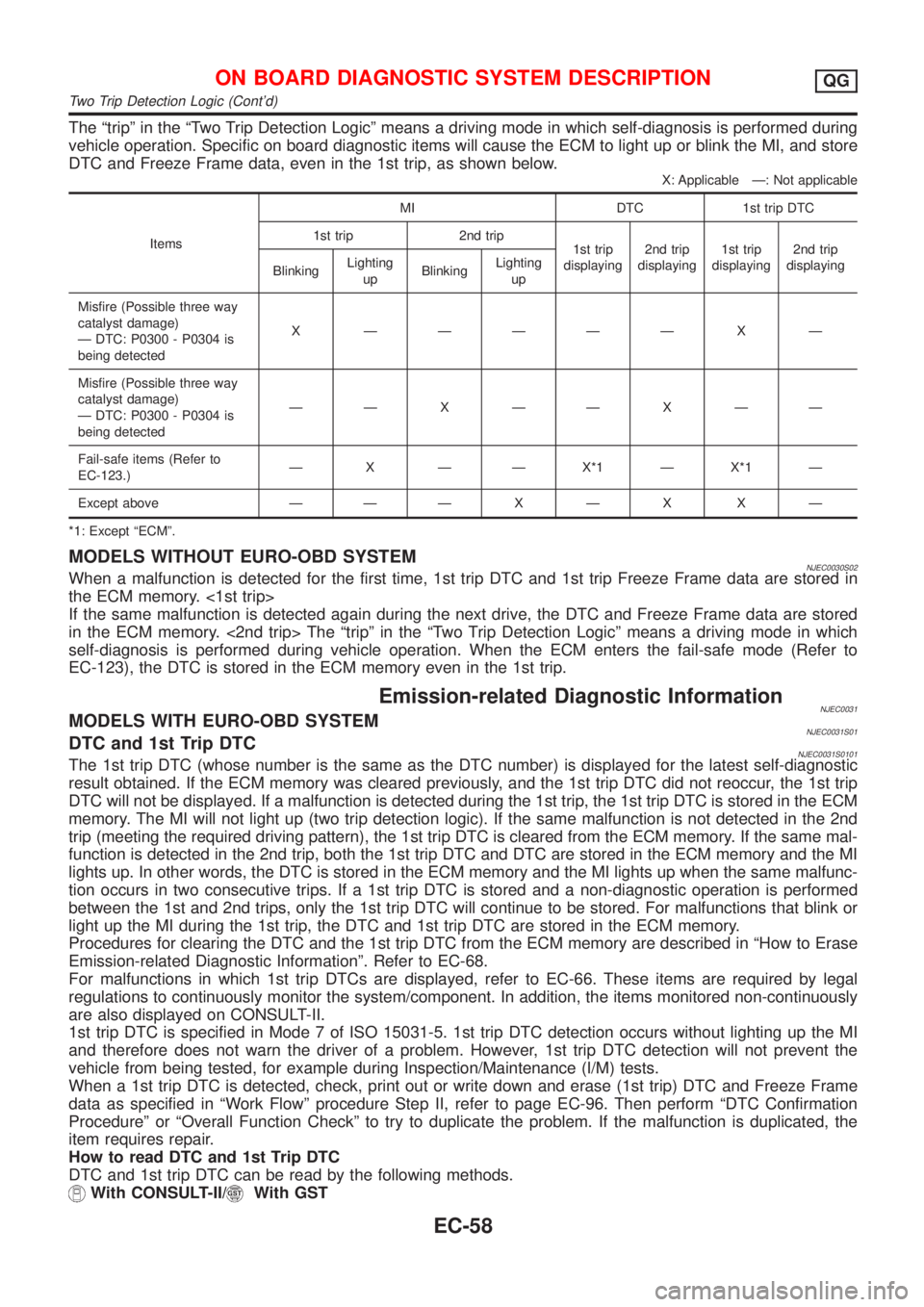
The ªtripº in the ªTwo Trip Detection Logicº means a driving mode in which self-diagnosis is performed during
vehicle operation. Specific on board diagnostic items will cause the ECM to light up or blink the MI, and store
DTC and Freeze Frame data, even in the 1st trip, as shown below.
X: Applicable Ð: Not applicable
ItemsMI DTC 1st trip DTC
1st trip 2nd trip
1st trip
displaying2nd trip
displaying1st trip
displaying2nd trip
displaying
BlinkingLighting
upBlinkingLighting
up
Misfire (Possible three way
catalyst damage)
Ð DTC: P0300 - P0304 is
being detectedX ÐÐÐÐÐ X Ð
Misfire (Possible three way
catalyst damage)
Ð DTC: P0300 - P0304 is
being detectedÐÐXÐÐXÐÐ
Fail-safe items (Refer to
EC-123.)Ð X Ð Ð X*1 Ð X*1 Ð
Except above Ð ÐÐXÐX XÐ
*1: Except ªECMº.
MODELS WITHOUT EURO-OBD SYSTEMNJEC0030S02When a malfunction is detected for the first time, 1st trip DTC and 1st trip Freeze Frame data are stored in
the ECM memory. <1st trip>
If the same malfunction is detected again during the next drive, the DTC and Freeze Frame data are stored
in the ECM memory. <2nd trip> The ªtripº in the ªTwo Trip Detection Logicº means a driving mode in which
self-diagnosis is performed during vehicle operation. When the ECM enters the fail-safe mode (Refer to
EC-123), the DTC is stored in the ECM memory even in the 1st trip.
Emission-related Diagnostic InformationNJEC0031MODELS WITH EURO-OBD SYSTEMNJEC0031S01DTC and 1st Trip DTCNJEC0031S0101The 1st trip DTC (whose number is the same as the DTC number) is displayed for the latest self-diagnostic
result obtained. If the ECM memory was cleared previously, and the 1st trip DTC did not reoccur, the 1st trip
DTC will not be displayed. If a malfunction is detected during the 1st trip, the 1st trip DTC is stored in the ECM
memory. The MI will not light up (two trip detection logic). If the same malfunction is not detected in the 2nd
trip (meeting the required driving pattern), the 1st trip DTC is cleared from the ECM memory. If the same mal-
function is detected in the 2nd trip, both the 1st trip DTC and DTC are stored in the ECM memory and the MI
lights up. In other words, the DTC is stored in the ECM memory and the MI lights up when the same malfunc-
tion occurs in two consecutive trips. If a 1st trip DTC is stored and a non-diagnostic operation is performed
between the 1st and 2nd trips, only the 1st trip DTC will continue to be stored. For malfunctions that blink or
light up the MI during the 1st trip, the DTC and 1st trip DTC are stored in the ECM memory.
Procedures for clearing the DTC and the 1st trip DTC from the ECM memory are described in ªHow to Erase
Emission-related Diagnostic Informationº. Refer to EC-68.
For malfunctions in which 1st trip DTCs are displayed, refer to EC-66. These items are required by legal
regulations to continuously monitor the system/component. In addition, the items monitored non-continuously
are also displayed on CONSULT-II.
1st trip DTC is specified in Mode 7 of ISO 15031-5. 1st trip DTC detection occurs without lighting up the MI
and therefore does not warn the driver of a problem. However, 1st trip DTC detection will not prevent the
vehicle from being tested, for example during Inspection/Maintenance (I/M) tests.
When a 1st trip DTC is detected, check, print out or write down and erase (1st trip) DTC and Freeze Frame
data as specified in ªWork Flowº procedure Step II, refer to page EC-96. Then perform ªDTC Confirmation
Procedureº or ªOverall Function Checkº to try to duplicate the problem. If the malfunction is duplicated, the
item requires repair.
How to read DTC and 1st Trip DTC
DTC and 1st trip DTC can be read by the following methods.
With CONSULT-II/With GST
ON BOARD DIAGNOSTIC SYSTEM DESCRIPTIONQG
Two Trip Detection Logic (Cont'd)
EC-58
Page 357 of 2493
Self-diagnosis resultExample
DiagnosisIgnition cycle
¬ON®OFF¬ON®OFF¬ON®OFF¬ON®
All OK Case 1 P0400 OK (1) Ð (1) OK (2) Ð (2)
P0402 OK (1) Ð (1) Ð (1) OK (2)
P1402 OK (1) OK (2) Ð (2) Ð (2)
SRT of EGR ªCMPLTº ªCMPLTº ªCMPLTº ªCMPLTº
Case 2 P0400 OK (1) Ð (1) Ð (1) Ð (1)
P0402 Ð (0) Ð (0) OK (1) Ð (1)
P1402 OK (1) OK (2) Ð (2) Ð (2)
SRT of EGR ªINCMPº ªINCMPº ªCMPLTº ªCMPLTº
NG exists Case 3 P0400 OK OK Ð Ð
P0402 Ð Ð Ð Ð
P1402 NG Ð NGNG
(Consecutive NG)
(1st trip)
DTC1st trip DTC Ð 1st trip DTCDTC
(= MIL ªONº)
SRT of EGR ªINCMPº ªINCMPº ªINCMPº ªCMPLTº
OK: Self-diagnosis is carried out and the result is OK.
NG: Self-diagnosis is carried out and the result is NG.
Ð: Self-diagnosis is not carried out.
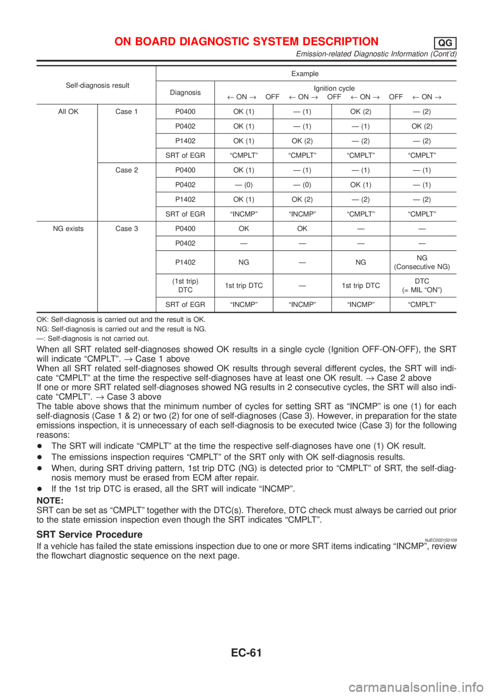
When all SRT related self-diagnoses showed OK results in a single cycle (Ignition OFF-ON-OFF), the SRT
will indicate ªCMPLTº.®Case 1 above
When all SRT related self-diagnoses showed OK results through several different cycles, the SRT will indi-
cate ªCMPLTº at the time the respective self-diagnoses have at least one OK result.®Case 2 above
If one or more SRT related self-diagnoses showed NG results in 2 consecutive cycles, the SRT will also indi-
cate ªCMPLTº.®Case 3 above
The table above shows that the minimum number of cycles for setting SRT as ªINCMPº is one (1) for each
self-diagnosis (Case1&2)ortwo(2)foroneofself-diagnoses (Case 3). However, in preparation for the state
emissions inspection, it is unnecessary of each self-diagnosis to be executed twice (Case 3) for the following
reasons:
+The SRT will indicate ªCMPLTº at the time the respective self-diagnoses have one (1) OK result.
+The emissions inspection requires ªCMPLTº of the SRT only with OK self-diagnosis results.
+When, during SRT driving pattern, 1st trip DTC (NG) is detected prior to ªCMPLTº of SRT, the self-diag-
nosis memory must be erased from ECM after repair.
+If the 1st trip DTC is erased, all the SRT will indicate ªINCMPº.
NOTE:
SRT can be set as ªCMPLTº together with the DTC(s). Therefore, DTC check must always be carried out prior
to the state emission inspection even though the SRT indicates ªCMPLTº.
SRT Service ProcedureNJEC0031S0109If a vehicle has failed the state emissions inspection due to one or more SRT items indicating ªINCMPº, review
the flowchart diagnostic sequence on the next page.
ON BOARD DIAGNOSTIC SYSTEM DESCRIPTIONQG
Emission-related Diagnostic Information (Cont'd)
EC-61
Page 359 of 2493
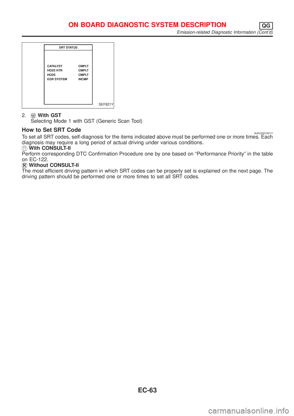
SEF821Y
2.With GST
Selecting Mode 1 with GST (Generic Scan Tool)
How to Set SRT CodeNJEC0031S0111To set all SRT codes, self-diagnosis for the items indicated above must be performed one or more times. Each
diagnosis may require a long period of actual driving under various conditions.
With CONSULT-II
Perform corresponding DTC Confirmation Procedure one by one based on ªPerformance Priorityº in the table
on EC-122.
Without CONSULT-II
The most efficient driving pattern in which SRT codes can be properly set is explained on the next page. The
driving pattern should be performed one or more times to set all SRT codes.
ON BOARD DIAGNOSTIC SYSTEM DESCRIPTIONQG
Emission-related Diagnostic Information (Cont'd)
EC-63
Page 362 of 2493

SRT item Self-diagnostic test itemTest value (GST display)
Test limit Application
TID CID
HO2SHeated oxygen sensor 1
(front)09H 04H Max. X
0AH 84H Min. X
0BH 04H Max. X
0CH 04H Max. X
0DH 04H Max. X
Heated oxygen sensor 2
(rear)19H 86H Min. X
1AH 86H Min. X
1BH 06H Max. X
1CH 06H Max. X
HO2S HTRHeated oxygen sensor 1
heater (front)29H 08H Max. X
2AH 88H Min. X
Heated oxygen sensor 2
heater (rear)2DH 0AH Max. X
2EH 8AH Min. X
EGR SYSTEM
(where fitted)EGR function31H 8CH Min. X
32H 8CH Min. X
33H 8CH Min. X
34H 8CH Min. X
35H 0CH Max. X
Emission-related Diagnostic Information ItemsNJEC0031S0105X: Applicable Ð: Not applicable
Items
(CONSULT-II screen terms)DTC*1 SRT codeTest value/Test
limit
(GST only)1st trip DTC*1 Reference page
NO SELF DIAGNOSTIC FAIL-
URE INDICATEDP0000ÐÐÐÐ
MAF SEN/CIRCUIT P0100 Ð Ð X EC-152
AIR TEMP SEN/CIRC P0110 Ð Ð X EC-158
COOLANT T SEN/CIRC P0115 Ð Ð X EC-163
THRTL POS SEN/CIRC P0120 Ð Ð X EC-168
HO2S1 (B1) P0130 X X X*2 EC-176
HO2S1 (B1) P0131 X X X*2 EC-183
HO2S1 (B1) P0132 X X X*2 EC-189
HO2S1 (B1) P0133 X X X*2 EC-195
HO2S1 (B1) P0134 X X X*2 EC-203
HO2S1 HTR (B1) P0135 X X X*2 EC-209
HO2S2 (B1) P0137 X X X*2 EC-214
HO2S2 (B1) P0138 X X X*2 EC-222
HO2S2 (B1) P0139 X X X*2 EC-229
ON BOARD DIAGNOSTIC SYSTEM DESCRIPTIONQG
Emission-related Diagnostic Information (Cont'd)
EC-66
Page 363 of 2493

Items
(CONSULT-II screen terms)DTC*1 SRT codeTest value/Test
limit
(GST only)1st trip DTC*1 Reference page
HO2S2 (B1) P0140 X X X*2 EC-237
HO2S2 HTR (B1) P0141 X X X*2 EC-243
FUEL SYS-LEAN/BK1 P0171 Ð Ð X EC-248
FUEL SYS-RICH/BK1 P0172 Ð Ð X EC-255
MULTI CYL MISFIRE P0300 Ð Ð X EC-262
CYL 1 MISFIRE P0301 Ð Ð X EC-262
CYL 2 MISFIRE P0302 Ð Ð X EC-262
CYL 3 MISFIRE P0303 Ð Ð X EC-262
CYL 4 MISFIRE P0304 Ð Ð X EC-262
KNOCK SEN/CIRC-B1 P0325 Ð Ð Ð EC-268
CKP SEN/CIRCUIT (POS) P0335 Ð Ð X EC-272
CMP SEN/CIRCUIT (PHS) P0340 Ð Ð X EC-278
EGR SYSTEM*3 P0400 X X X*2 EC-285
EGR VOL CONT/V CIRC*3 P0403 Ð Ð X EC-293
TW CATALYST SYS-B1 P0420 X X X*2 EC-299
PURG VOLUME CONT/V P0443 Ð Ð X EC-304
VEH SPEED SEN/CIRC P0500 Ð Ð X EC-309
IACV/AAC VLV/CIRC P0505 Ð Ð X EC-313
CLOSED TP SW/CIRC*3 P0510 Ð Ð X EC-321
ECM P0605 Ð Ð X EC-327
PNP SW/CIRC P0705 Ð Ð XRefer to AT sec-
tion.
ATF TEMP SEN/CIRC P0710 Ð Ð XRefer to AT sec-
tion.
VEH SPD SEN/CIR AT P0720 Ð Ð XRefer to AT sec-
tion.
ENGINE SPEED SIG P0725 Ð Ð XRefer to AT sec-
tion.
A/T 1ST GR FNCTN P0731 Ð Ð XRefer to AT sec-
tion.
A/T 2ND GR FNCTN P0732 Ð Ð XRefer to AT sec-
tion.
A/T 3RD GR FNCTN P0733 Ð Ð XRefer to AT sec-
tion.
A/T 4TH GR FNCTN P0734 Ð Ð XRefer to AT sec-
tion.
TCC SOLENOID/CIRC P0740 Ð Ð XRefer to AT sec-
tion.
L/PRESS SOL/CIRC P0745 Ð Ð XRefer to AT sec-
tion.
ON BOARD DIAGNOSTIC SYSTEM DESCRIPTIONQG
Emission-related Diagnostic Information (Cont'd)
EC-67
Page 364 of 2493
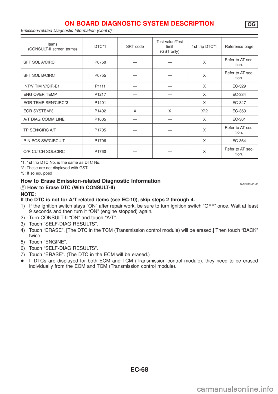
Items
(CONSULT-II screen terms)DTC*1 SRT codeTest value/Test
limit
(GST only)1st trip DTC*1 Reference page
SFT SOL A/CIRC P0750 Ð Ð XRefer to AT sec-
tion.
SFT SOL B/CIRC P0755 Ð Ð XRefer to AT sec-
tion.
INT/V TIM V/CIR-B1 P1111 Ð Ð XEC-329
ENG OVER TEMP P1217 Ð Ð X EC-334
EGR TEMP SEN/CIRC*3 P1401 Ð Ð X EC-347
EGR SYSTEM*3 P1402 X X X*2 EC-353
A/T DIAG COMM LINE P1605 Ð Ð X EC-361
TP SEN/CIRC A/T P1705 Ð Ð XRefer to AT sec-
tion.
P-N POS SW/CIRCUIT P1706 Ð Ð X EC-364
O/R CLTCH SOL/CIRC P1760 Ð Ð XRefer to AT sec-
tion.
*1: 1st trip DTC No. is the same as DTC No.
*2: These are not displayed with GST.
*3: If so equipped
How to Erase Emission-related Diagnostic InformationNJEC0031S0106How to Erase DTC (With CONSULT-II)
NOTE:
If the DTC is not for A/T related items (see EC-10), skip steps 2 through 4.
1) If the ignition switch stays ªONº after repair work, be sure to turn ignition switch ªOFFº once. Wait at least
9 seconds and then turn it ªONº (engine stopped) again.
2) Turn CONSULT-II ªONº and touch ªA/Tº.
3) Touch ªSELF-DIAG RESULTSº.
4) Touch ªERASEº. [The DTC in the TCM (Transmission control module) will be erased.] Then touch ªBACKº
twice.
5) Touch ªENGINEº.
6) Touch ªSELF-DIAG RESULTSº.
7) Touch ªERASEº. (The DTC in the ECM will be erased.)
+If DTCs are displayed for both ECM and TCM (Transmission control module), they need to be erased
individually from the ECM and TCM (Transmission control module).
ON BOARD DIAGNOSTIC SYSTEM DESCRIPTIONQG
Emission-related Diagnostic Information (Cont'd)
EC-68