2001 NISSAN ALMERA N16 EL page 71
[x] Cancel search: EL page 71Page 1063 of 2493
NJMT0003
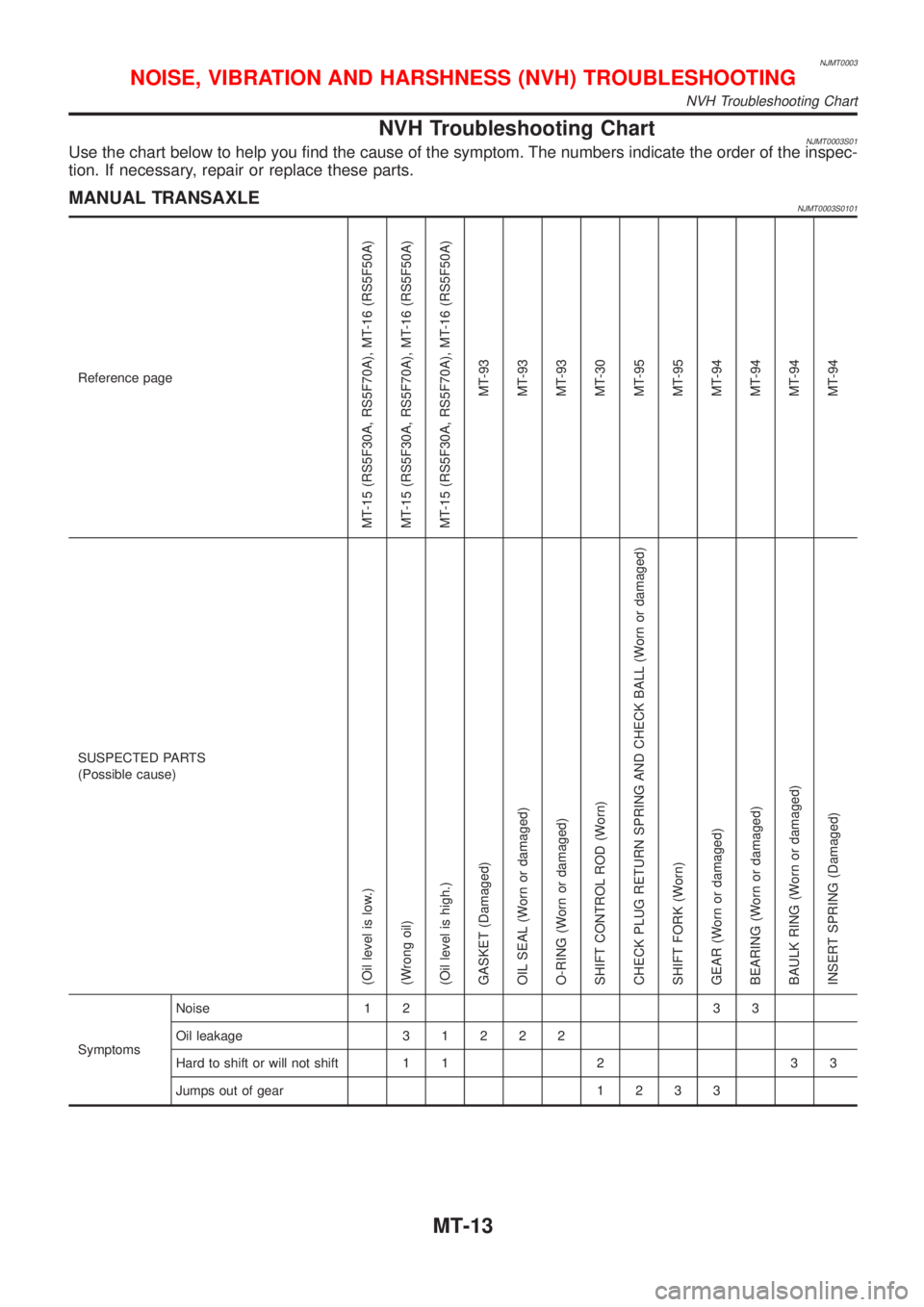
NVH Troubleshooting ChartNJMT0003S01Use the chart below to help you find the cause of the symptom. The numbers indicate the order of the inspec-
tion. If necessary, repair or replace these parts.
MANUAL TRANSAXLENJMT0003S0101
Reference page
MT-15 (RS5F30A, RS5F70A), MT-16 (RS5F50A)
MT-15 (RS5F30A, RS5F70A), MT-16 (RS5F50A)
MT-15 (RS5F30A, RS5F70A), MT-16 (RS5F50A)
MT-93
MT-93
MT-93
MT-30
MT-95
MT-95
MT-94
MT-94
MT-94
MT-94
SUSPECTED PARTS
(Possible cause)
(Oil level is low.)
(Wrong oil)
(Oil level is high.)
GASKET (Damaged)
OIL SEAL (Worn or damaged)
O-RING (Worn or damaged)
SHIFT CONTROL ROD (Worn)
CHECK PLUG RETURN SPRING AND CHECK BALL (Worn or damaged)
SHIFT FORK (Worn)
GEAR (Worn or damaged)
BEARING (Worn or damaged)
BAULK RING (Worn or damaged)
INSERT SPRING (Damaged)
SymptomsNoise 1 2 3 3
Oil leakage31222
Hard to shift or will not shift 1 1 2 3 3
Jumps out of gear1233
NOISE, VIBRATION AND HARSHNESS (NVH) TROUBLESHOOTING
NVH Troubleshooting Chart
MT-13
Page 1191 of 2493
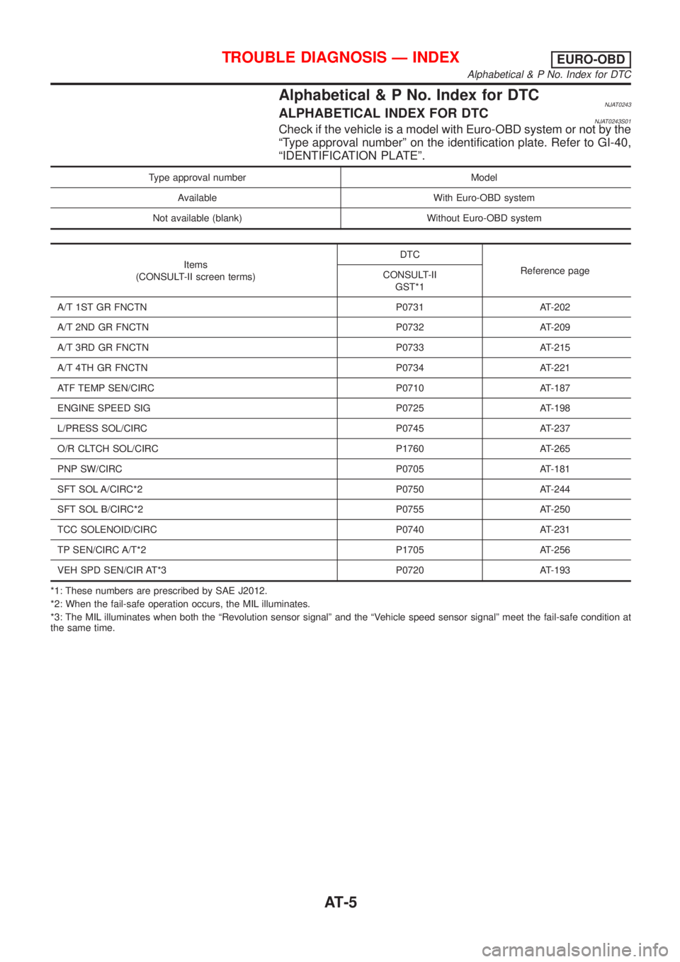
Alphabetical & P No. Index for DTCNJAT0243ALPHABETICAL INDEX FOR DTCNJAT0243S01Check if the vehicle is a model with Euro-OBD system or not by the
ªType approval numberº on the identification plate. Refer to GI-40,
ªIDENTIFICATION PLATEº.
Type approval number Model
Available With Euro-OBD system
Not available (blank) Without Euro-OBD system
Items
(CONSULT-II screen terms)DTC
Reference page
CONSULT-II
GST*1
A/T 1ST GR FNCTN P0731 AT-202
A/T 2ND GR FNCTN P0732 AT-209
A/T 3RD GR FNCTN P0733 AT-215
A/T 4TH GR FNCTN P0734 AT-221
ATF TEMP SEN/CIRC P0710 AT-187
ENGINE SPEED SIG P0725 AT-198
L/PRESS SOL/CIRC P0745 AT-237
O/R CLTCH SOL/CIRC P1760 AT-265
PNP SW/CIRC P0705 AT-181
SFT SOL A/CIRC*2 P0750 AT-244
SFT SOL B/CIRC*2 P0755 AT-250
TCC SOLENOID/CIRC P0740 AT-231
TP SEN/CIRC A/T*2 P1705 AT-256
VEH SPD SEN/CIR AT*3 P0720 AT-193
*1: These numbers are prescribed by SAE J2012.
*2: When the fail-safe operation occurs, the MIL illuminates.
*3: The MIL illuminates when both the ªRevolution sensor signalº and the ªVehicle speed sensor signalº meet the fail-safe condition at
the same time.
TROUBLE DIAGNOSIS Ð INDEXEURO-OBD
Alphabetical & P No. Index for DTC
AT-5
Page 1192 of 2493
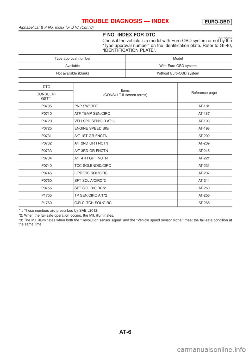
P NO. INDEX FOR DTC=NJAT0243S02Check if the vehicle is a model with Euro-OBD system or not by the
ªType approval numberº on the identification plate. Refer to GI-40,
ªIDENTIFICATION PLATEº.
Type approval number Model
Available With Euro-OBD system
Not available (blank) Without Euro-OBD system
DTC
Items
(CONSULT-II screen terms)Reference page
CONSULT-II
GST*1
P0705 PNP SW/CIRC AT-181
P0710 ATF TEMP SEN/CIRC AT-187
P0720 VEH SPD SEN/CIR AT*3 AT-193
P0725 ENGINE SPEED SIG AT-198
P0731 A/T 1ST GR FNCTN AT-202
P0732 A/T 2ND GR FNCTN AT-209
P0733 A/T 3RD GR FNCTN AT-215
P0734 A/T 4TH GR FNCTN AT-221
P0740 TCC SOLENOID/CIRC AT-231
P0745 L/PRESS SOL/CIRC AT-237
P0750 SFT SOL A/CIRC*2 AT-244
P0755 SFT SOL B/CIRC*2 AT-250
P1705 TP SEN/CIRC A/T*2 AT-256
P1760 O/R CLTCH SOL/CIRC AT-265
*1: These numbers are prescribed by SAE J2012.
*2: When the fail-safe operation occurs, the MIL illuminates.
*3: The MIL illuminates when both the ªRevolution sensor signalº and the ªVehicle speed sensor signalº meet the fail-safe condition at
the same time.
TROUBLE DIAGNOSIS Ð INDEXEURO-OBD
Alphabetical & P No. Index for DTC (Cont'd)
AT-6
Page 1194 of 2493
AAT470A
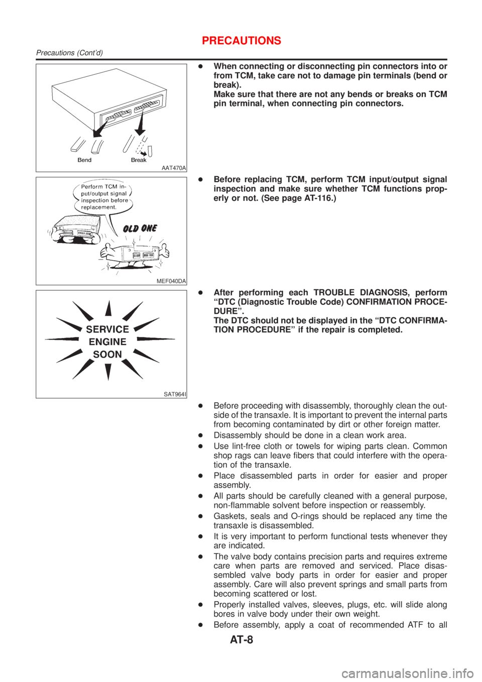
+When connecting or disconnecting pin connectors into or
from TCM, take care not to damage pin terminals (bend or
break).
Make sure that there are not any bends or breaks on TCM
pin terminal, when connecting pin connectors.
MEF040DA
+Before replacing TCM, perform TCM input/output signal
inspection and make sure whether TCM functions prop-
erly or not. (See page AT-116.)
SAT964I
+After performing each TROUBLE DIAGNOSIS, perform
ªDTC (Diagnostic Trouble Code) CONFIRMATION PROCE-
DUREº.
The DTC should not be displayed in the ªDTC CONFIRMA-
TION PROCEDUREº if the repair is completed.
+Before proceeding with disassembly, thoroughly clean the out-
side of the transaxle. It is important to prevent the internal parts
from becoming contaminated by dirt or other foreign matter.
+Disassembly should be done in a clean work area.
+Use lint-free cloth or towels for wiping parts clean. Common
shop rags can leave fibers that could interfere with the opera-
tion of the transaxle.
+Place disassembled parts in order for easier and proper
assembly.
+All parts should be carefully cleaned with a general purpose,
non-flammable solvent before inspection or reassembly.
+Gaskets, seals and O-rings should be replaced any time the
transaxle is disassembled.
+It is very important to perform functional tests whenever they
are indicated.
+The valve body contains precision parts and requires extreme
care when parts are removed and serviced. Place disas-
sembled valve body parts in order for easier and proper
assembly. Care will also prevent springs and small parts from
becoming scattered or lost.
+Properly installed valves, sleeves, plugs, etc. will slide along
bores in valve body under their own weight.
+Before assembly, apply a coat of recommended ATF to all
PRECAUTIONS
Precautions (Cont'd)
AT-8
Page 1223 of 2493
CONSULT-IINJAT0022After performing ªSELF-DIAGNOSTIC PROCEDURE (WITH CON-
SULT-II)º (AT-37), place check marks for results on the ªDIAGNOS-
TIC WORKSHEETº, AT-69. Reference pages are provided follow-
ing the items.
NOTICE:
1) The CONSULT-II electrically displays shift timing and lock-up
timing (that is, operation timing of each solenoid).
Check for time difference between actual shift timing and the
CONSULT-II display. If the difference is noticeable, mechani-
cal parts (except solenoids, sensors, etc.) may be malfunction-
ing. Check mechanical parts using applicable diagnostic pro-
cedures.
2) Shift schedule (which implies gear position) displayed on
CONSULT-II and that indicated in Service Manual may differ
slightly. This occurs because of the following reasons:
+Actual shift schedule has more or less tolerance or allowance,
+Shift schedule indicated in Service Manual refers to the point
where shifts start, and
+Gear position displayed on CONSULT-II indicates the point
where shifts are completed.
3) Shift solenoid valve ªAº or ªBº is displayed on CONSULT-II at
the start of shifting. Gear position is displayed upon completion
of shifting (which is computed by TCM).
4) Additional CONSULT-II information can be found in the Opera-
tion Manual supplied with the CONSULT-II unit.
SAT580J
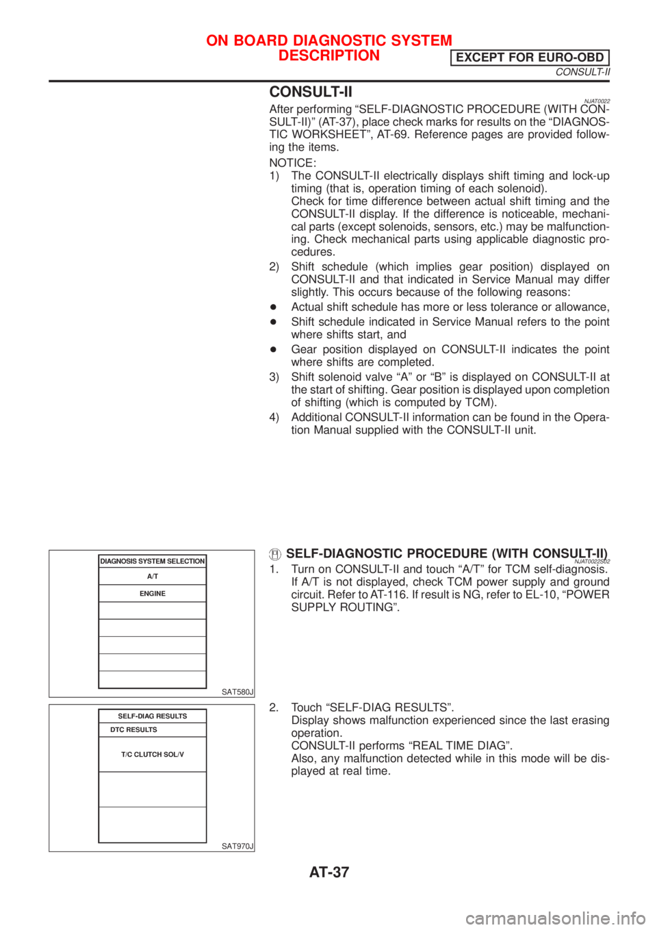
SELF-DIAGNOSTIC PROCEDURE (WITH CONSULT-II)NJAT0022S021. Turn on CONSULT-II and touch ªA/Tº for TCM self-diagnosis.
If A/T is not displayed, check TCM power supply and ground
circuit. Refer to AT-116. If result is NG, refer to EL-10, ªPOWER
SUPPLY ROUTINGº.
SAT970J
2. Touch ªSELF-DIAG RESULTSº.
Display shows malfunction experienced since the last erasing
operation.
CONSULT-II performs ªREAL TIME DIAGº.
Also, any malfunction detected while in this mode will be dis-
played at real time.
ON BOARD DIAGNOSTIC SYSTEM
DESCRIPTION
EXCEPT FOR EURO-OBD
CONSULT-II
AT-37
Page 1234 of 2493
IntroductionNJAT0251The A/T system has two self-diagnostic systems.
The first is the emission-related on board diagnostic system (EURO-OBD) performed by the TCM in combi-
nation with the ECM. The malfunction is indicated by the MI (malfunction indicator) and is stored as a DTC in
the ECM memory but not the TCM memory.
The second is the TCM original self-diagnosis indicated by the O/D OFF indicator lamp. The malfunction is
stored in the TCM memory. The detected items are overlapped with EURO-OBD self-diagnostic items. For
detail, refer to AT-53.
EURO-OBD Function for A/T SystemNJAT0252The ECM provides emission-related on board diagnostic (EURO-OBD) functions for the A/T system. One
function is to receive a signal from the TCM used with EURO-OBD-related parts of the A/T system. The sig-
nal is sent to the ECM when a malfunction occurs in the corresponding EURO-OBD-related part. The other
function is to indicate a diagnostic result by means of the MI (malfunction indicator) on the instrument panel.
Sensors, switches and solenoid valves are used as sensing elements.
The MI automatically illuminates in One or Two Trip Detection Logic when a malfunction is sensed in relation
to A/T system parts.
One or Two Trip Detection Logic of EURO-OBDNJAT0253ONE TRIP DETECTION LOGICNJAT0253S01If a malfunction is sensed during the first test drive, the MI will illuminate and the malfunction will be stored
in the ECM memory as a DTC. The TCM is not provided with such a memory function.
TWO TRIP DETECTION LOGICNJAT0253S02When a malfunction is sensed during the first test drive, it is stored in the ECM memory as a 1st trip DTC
(diagnostic trouble code) or 1st trip freeze frame data. At this point, the MI will not illuminate. Ð First Trip
If the same malfunction as that experienced during the first test drive is sensed during the second test drive,
the MI will illuminate. Ð Second Trip
A/T-related parts for which the MI illuminates during the first or second test drive are listed below.
ItemsMI
One trip detection Two trip detection
Shift solenoid valve A Ð DTC: P0750 X
Shift solenoid valve B Ð DTC: P0755 X
Throttle position sensor or switch Ð DTC: P1705 X
Except aboveX
The ªtripº in the ªOne or Two Trip Detection Logicº means a driving mode in which self-diagnosis is performed
during vehicle operation.
EURO-OBD Diagnostic Trouble Code (DTC)NJAT0254HOW TO READ DTC AND 1ST TRIP DTCNJAT0254S01DTC and 1st trip DTC can be read by the following methods.
(
with CONSULT-II orGST)CONSULT-II or GST (Generic Scan Tool) Examples: P0705, P0710, P0720,
P0725, etc.
These DTCs are prescribed by SAE J2012.
(CONSULT-II also displays the malfunctioning component or system.)
+1st trip DTC No. is the same as DTC No.
+Output of the diagnostic trouble code indicates that the indicated circuit has a malfunction.
However, in case of the Mode II and GST they do not indicate whether the malfunction is still
occurring or occurred in the past and returned to normal.
CONSULT-II can identify them as shown below. Therefore, using CONSULT-II (if available) is rec-
ommended.
A sample of CONSULT-II display for DTC is shown in the following page. DTC or 1st trip DTC of a malfunc-
tion is displayed in SELF DIAGNOSIS mode for ªENGINEº with CONSULT-II. Time data indicates how many
times the vehicle was driven after the last detection of a DTC.
ON BOARD DIAGNOSTIC SYSTEM DESCRIPTIONEURO-OBD
Introduction
AT-48
Page 1238 of 2493
SAT964I
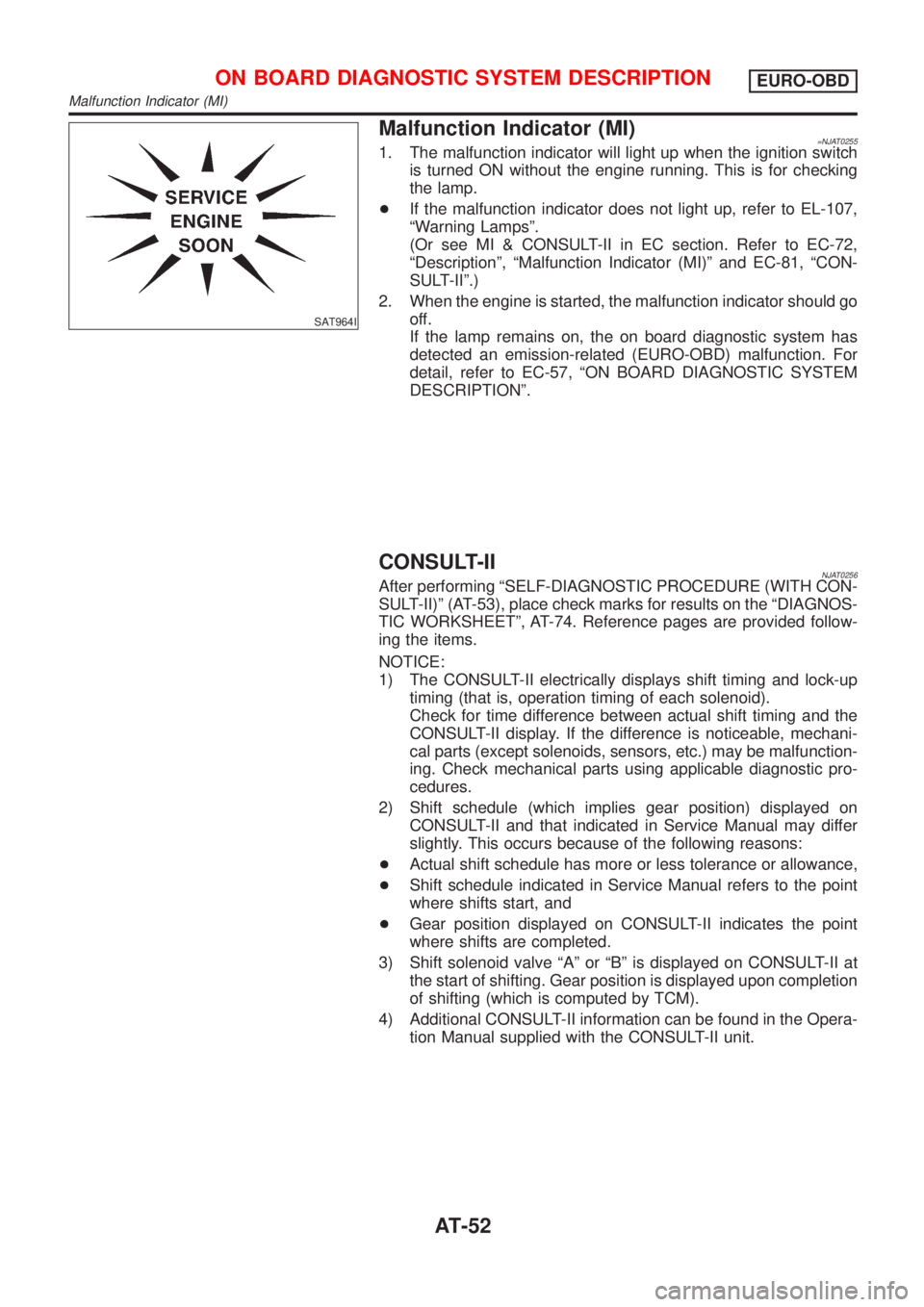
Malfunction Indicator (MI)=NJAT02551. The malfunction indicator will light up when the ignition switch
is turned ON without the engine running. This is for checking
the lamp.
+If the malfunction indicator does not light up, refer to EL-107,
ªWarning Lampsº.
(Or see MI & CONSULT-II in EC section. Refer to EC-72,
ªDescriptionº, ªMalfunction Indicator (MI)º and EC-81, ªCON-
SULT-IIº.)
2. When the engine is started, the malfunction indicator should go
off.
If the lamp remains on, the on board diagnostic system has
detected an emission-related (EURO-OBD) malfunction. For
detail, refer to EC-57, ªON BOARD DIAGNOSTIC SYSTEM
DESCRIPTIONº.
CONSULT-IINJAT0256After performing ªSELF-DIAGNOSTIC PROCEDURE (WITH CON-
SULT-II)º (AT-53), place check marks for results on the ªDIAGNOS-
TIC WORKSHEETº, AT-74. Reference pages are provided follow-
ing the items.
NOTICE:
1) The CONSULT-II electrically displays shift timing and lock-up
timing (that is, operation timing of each solenoid).
Check for time difference between actual shift timing and the
CONSULT-II display. If the difference is noticeable, mechani-
cal parts (except solenoids, sensors, etc.) may be malfunction-
ing. Check mechanical parts using applicable diagnostic pro-
cedures.
2) Shift schedule (which implies gear position) displayed on
CONSULT-II and that indicated in Service Manual may differ
slightly. This occurs because of the following reasons:
+Actual shift schedule has more or less tolerance or allowance,
+Shift schedule indicated in Service Manual refers to the point
where shifts start, and
+Gear position displayed on CONSULT-II indicates the point
where shifts are completed.
3) Shift solenoid valve ªAº or ªBº is displayed on CONSULT-II at
the start of shifting. Gear position is displayed upon completion
of shifting (which is computed by TCM).
4) Additional CONSULT-II information can be found in the Opera-
tion Manual supplied with the CONSULT-II unit.
ON BOARD DIAGNOSTIC SYSTEM DESCRIPTIONEURO-OBD
Malfunction Indicator (MI)
AT-52
Page 1265 of 2493
SAT513G
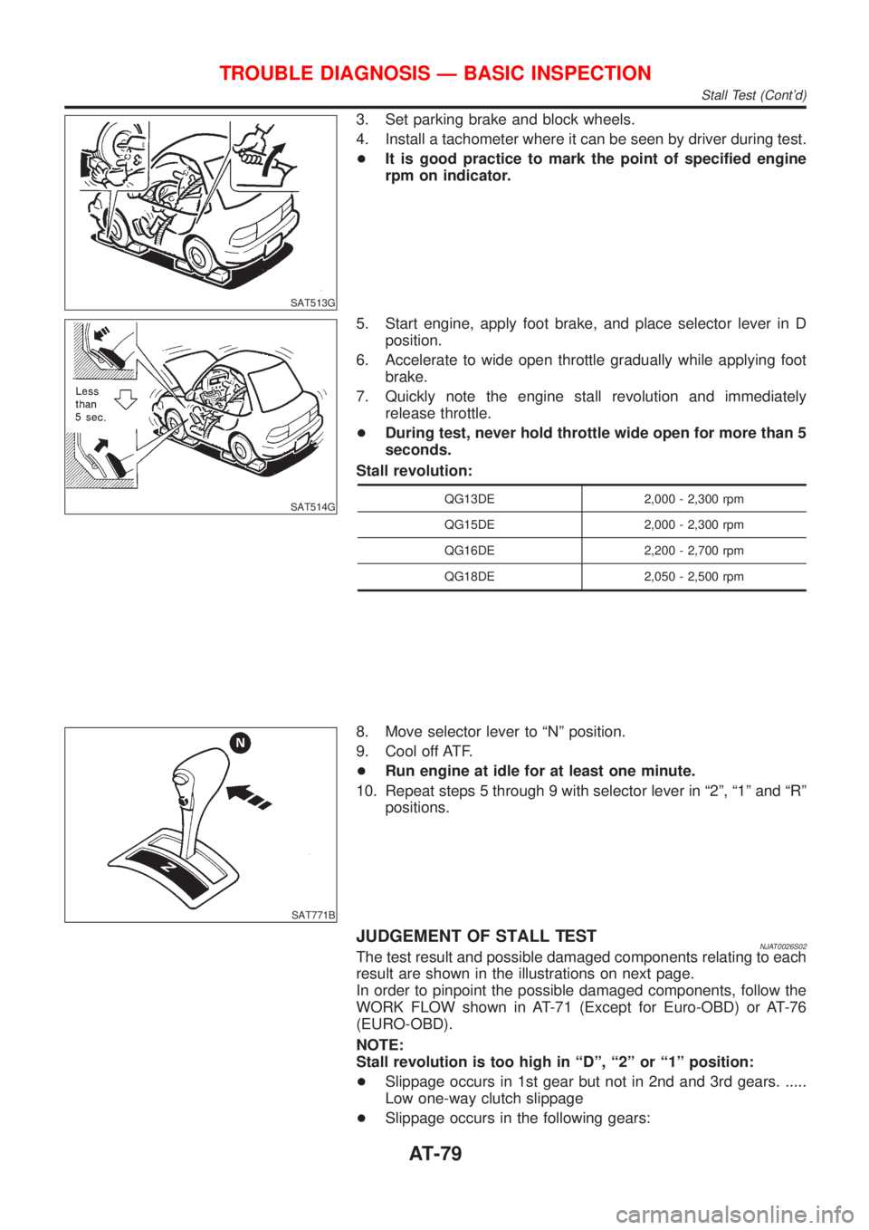
3. Set parking brake and block wheels.
4. Install a tachometer where it can be seen by driver during test.
+It is good practice to mark the point of specified engine
rpm on indicator.
SAT514G
5. Start engine, apply foot brake, and place selector lever in D
position.
6. Accelerate to wide open throttle gradually while applying foot
brake.
7. Quickly note the engine stall revolution and immediately
release throttle.
+During test, never hold throttle wide open for more than 5
seconds.
Stall revolution:
QG13DE 2,000 - 2,300 rpm
QG15DE 2,000 - 2,300 rpm
QG16DE 2,200 - 2,700 rpm
QG18DE 2,050 - 2,500 rpm
SAT771B
8. Move selector lever to ªNº position.
9. Cool off ATF.
+Run engine at idle for at least one minute.
10. Repeat steps 5 through 9 with selector lever in ª2º, ª1º and ªRº
positions.
JUDGEMENT OF STALL TESTNJAT0026S02The test result and possible damaged components relating to each
result are shown in the illustrations on next page.
In order to pinpoint the possible damaged components, follow the
WORK FLOW shown in AT-71 (Except for Euro-OBD) or AT-76
(EURO-OBD).
NOTE:
Stall revolution is too high in ªDº, ª2º or ª1º position:
+Slippage occurs in 1st gear but not in 2nd and 3rd gears. .....
Low one-way clutch slippage
+Slippage occurs in the following gears:
TROUBLE DIAGNOSIS Ð BASIC INSPECTION
Stall Test (Cont'd)
AT-79