2001 NISSAN ALMERA N16 EL page 71
[x] Cancel search: EL page 71Page 1570 of 2493
Control Valve Upper Body
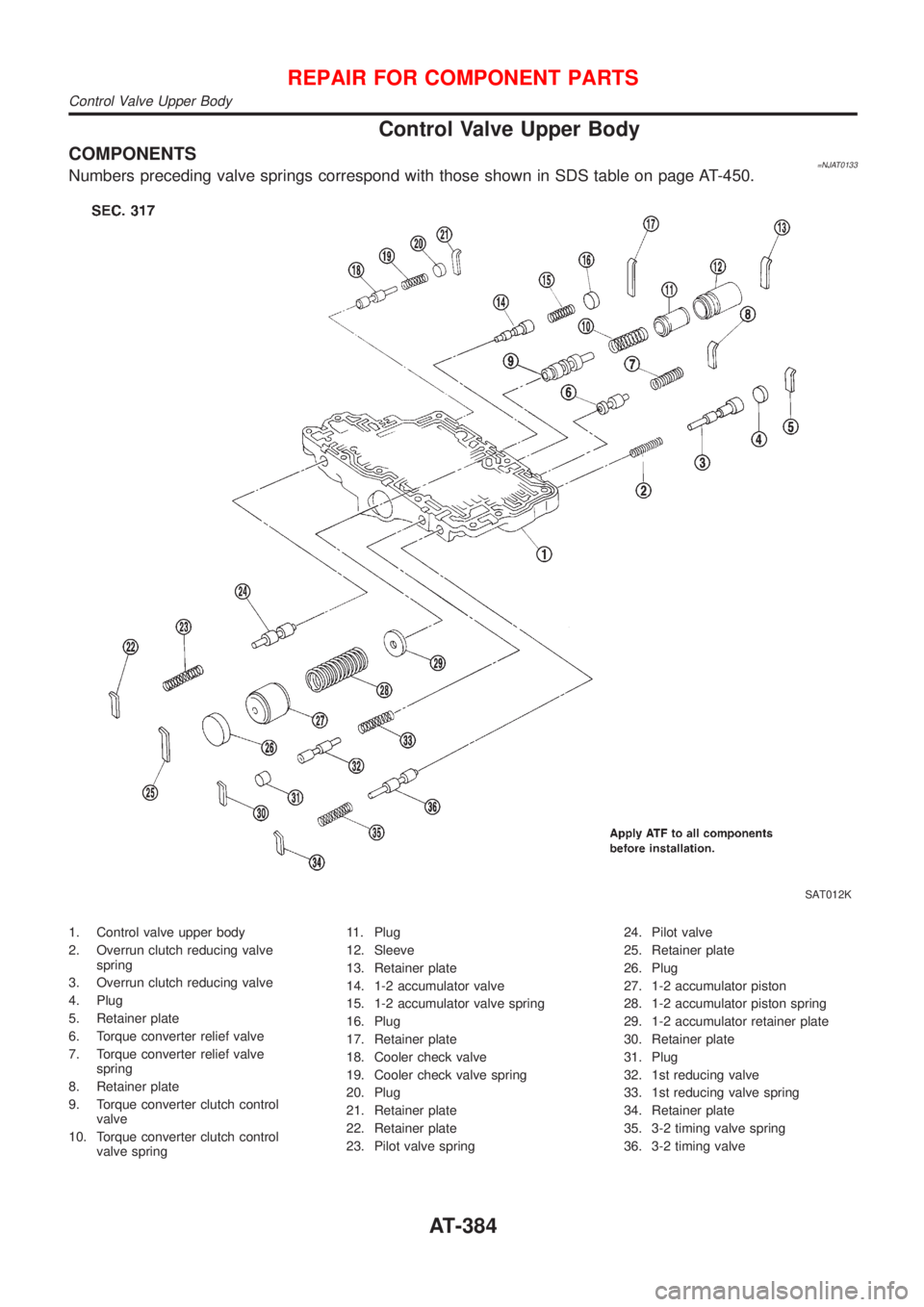
COMPONENTS=NJAT0133Numbers preceding valve springs correspond with those shown in SDS table on page AT-450.
SAT012K
1. Control valve upper body
2. Overrun clutch reducing valve
spring
3. Overrun clutch reducing valve
4. Plug
5. Retainer plate
6. Torque converter relief valve
7. Torque converter relief valve
spring
8. Retainer plate
9. Torque converter clutch control
valve
10. Torque converter clutch control
valve spring11. Plug
12. Sleeve
13. Retainer plate
14. 1-2 accumulator valve
15. 1-2 accumulator valve spring
16. Plug
17. Retainer plate
18. Cooler check valve
19. Cooler check valve spring
20. Plug
21. Retainer plate
22. Retainer plate
23. Pilot valve spring24. Pilot valve
25. Retainer plate
26. Plug
27. 1-2 accumulator piston
28. 1-2 accumulator piston spring
29. 1-2 accumulator retainer plate
30. Retainer plate
31. Plug
32. 1st reducing valve
33. 1st reducing valve spring
34. Retainer plate
35. 3-2 timing valve spring
36. 3-2 timing valve
REPAIR FOR COMPONENT PARTS
Control Valve Upper Body
AT-384
Page 1574 of 2493
Control Valve Lower Body
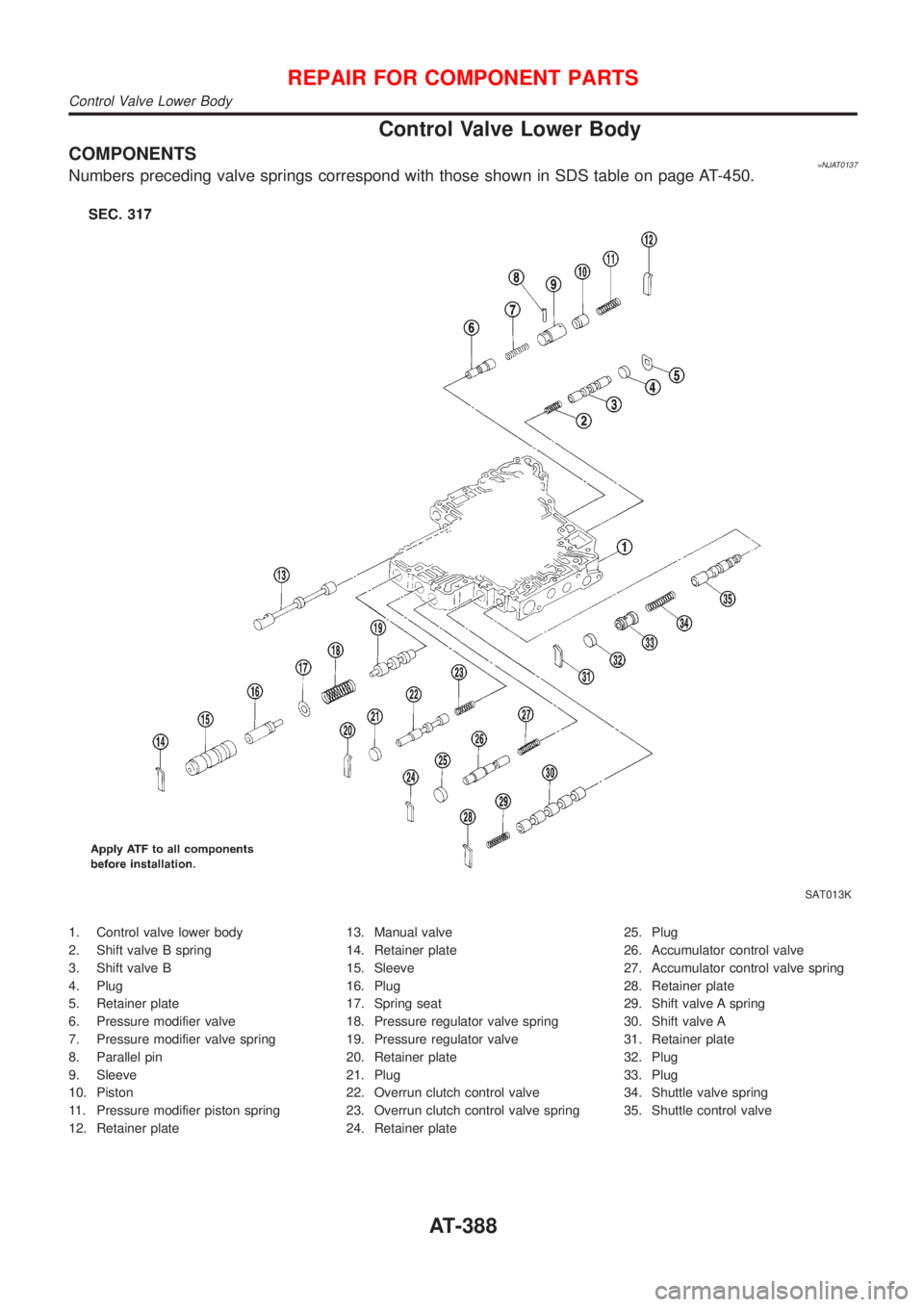
COMPONENTS=NJAT0137Numbers preceding valve springs correspond with those shown in SDS table on page AT-450.
SAT013K
1. Control valve lower body
2. Shift valve B spring
3. Shift valve B
4. Plug
5. Retainer plate
6. Pressure modifier valve
7. Pressure modifier valve spring
8. Parallel pin
9. Sleeve
10. Piston
11. Pressure modifier piston spring
12. Retainer plate13. Manual valve
14. Retainer plate
15. Sleeve
16. Plug
17. Spring seat
18. Pressure regulator valve spring
19. Pressure regulator valve
20. Retainer plate
21. Plug
22. Overrun clutch control valve
23. Overrun clutch control valve spring
24. Retainer plate25. Plug
26. Accumulator control valve
27. Accumulator control valve spring
28. Retainer plate
29. Shift valve A spring
30. Shift valve A
31. Retainer plate
32. Plug
33. Plug
34. Shuttle valve spring
35. Shuttle control valve
REPAIR FOR COMPONENT PARTS
Control Valve Lower Body
AT-388
Page 1647 of 2493
Noise, Vibration and Harshness (NVH)
Troubleshooting
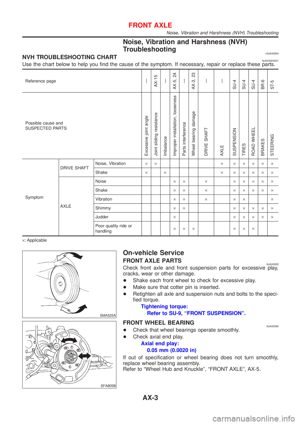
=NJAX0004NVH TROUBLESHOOTING CHARTNJAX0004S01Use the chart below to help you find the cause of the symptom. If necessary, repair or replace these parts.
Reference pageÐ
AX-15
Ð
AX-5, 24
Ð
AX-3, 23
Ð
Ð
SU-4
SU-4
SU-4
BR-6
ST-5
Possible cause and
SUSPECTED PARTS
Excessive joint angle
Joint sliding resistance
Imbalance
Improper installation, looseness
Parts interference
Wheel bearing damage
DRIVE SHAFT
AXLE
SUSPENSION
TIRES
ROAD WHEEL
BRAKES
STEERING
SymptomDRIVE SHAFTNoise, Vibration´´ ´ ´´´´´
Shake´ ´ ´ ´´´´´
AXLENoise´´ ´ ´´´´´
Shake´´ ´ ´´´´´
Vibration´´ ´ ´´ ´
Shimmy´´ ´´´´´
Judder´ ´´´´´
Poor quality ride or
handling´´´ ´´´
´: Applicable
SMA525A
On-vehicle Service
FRONT AXLE PARTSNJAX0005Check front axle and front suspension parts for excessive play,
cracks, wear or other damage.
+Shake each front wheel to check for excessive play.
+Make sure that cotter pin is inserted.
+Retighten all axle and suspension nuts and bolts to the speci-
fied torque.
Tightening torque:
Refer to SU-9, ªFRONT SUSPENSIONº.
SFA805B
FRONT WHEEL BEARINGNJAX0006+Check that wheel bearings operate smoothly.
+Check axial end play.
Axial end play:
0.05 mm (0.0020 in)
If out of specification or wheel bearing does not turn smoothly,
replace wheel bearing assembly.
Refer to ªWheel Hub and Knuckleº, ªFRONT AXLEº, AX-5.
FRONT AXLE
Noise, Vibration and Harshness (NVH) Troubleshooting
AX-3
Page 1676 of 2493
Noise, Vibration and Harshness (NVH)
Troubleshooting
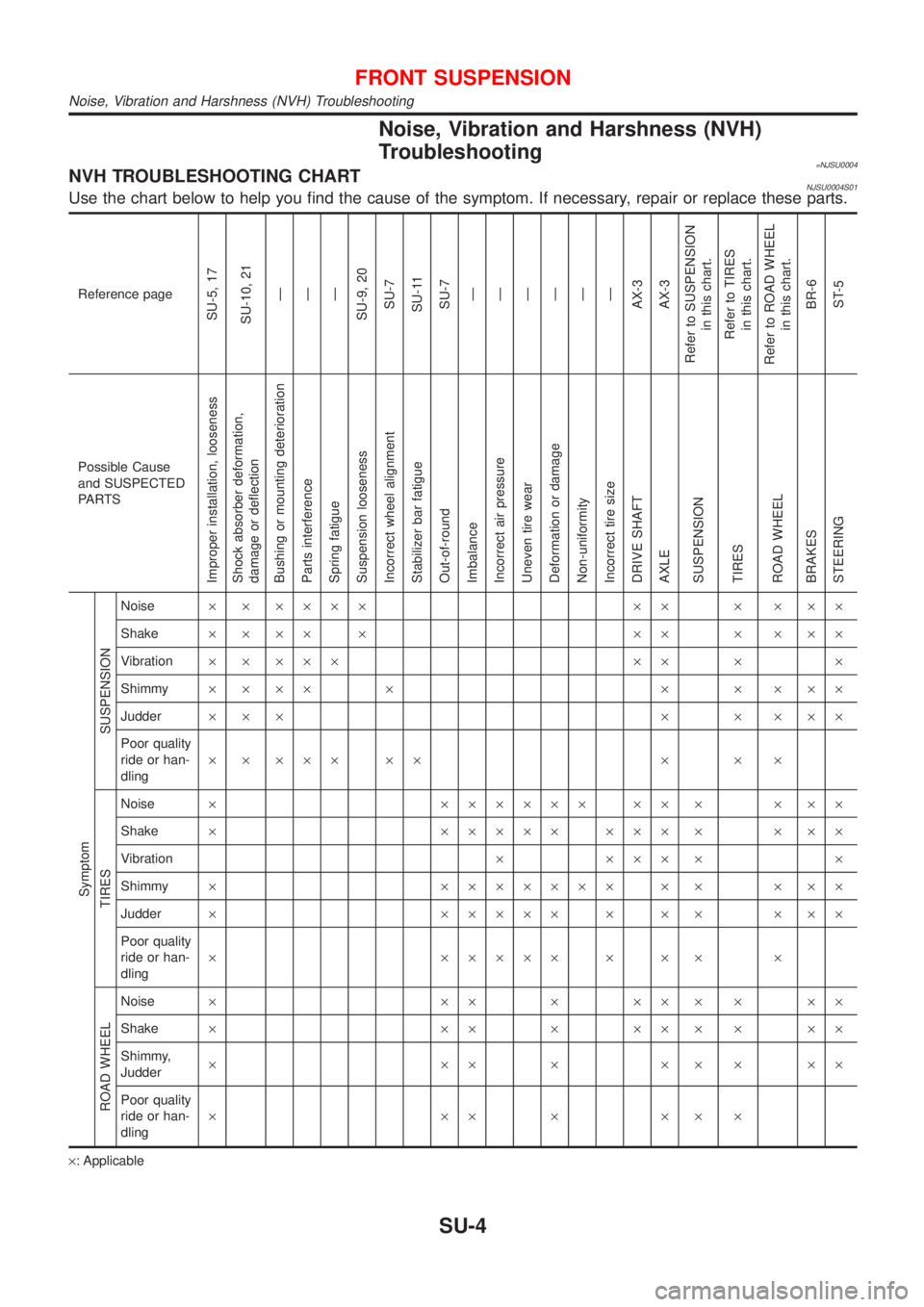
=NJSU0004NVH TROUBLESHOOTING CHARTNJSU0004S01Use the chart below to help you find the cause of the symptom. If necessary, repair or replace these parts.
Reference page
SU-5, 17
SU-10, 21
Ð
Ð
Ð
SU-9, 20
SU-7
SU-11
SU-7
Ð
Ð
Ð
Ð
Ð
Ð
AX-3
AX-3
Refer to SUSPENSION
in this chart.
Refer to TIRES
in this chart.
Refer to ROAD WHEEL
in this chart.
BR-6
ST-5
Possible Cause
and SUSPECTED
PA R T S
Improper installation, looseness
Shock absorber deformation,
damage or deflection
Bushing or mounting deterioration
Parts interference
Spring fatigue
Suspension looseness
Incorrect wheel alignment
Stabilizer bar fatigue
Out-of-round
Imbalance
Incorrect air pressure
Uneven tire wear
Deformation or damage
Non-uniformity
Incorrect tire size
DRIVE SHAFT
AXLE
SUSPENSION
TIRES
ROAD WHEEL
BRAKES
STEERING Symptom
SUSPENSION
Noise´ ´ ´´´´ ´´ ´ ´ ´´
Shake´ ´ ´´ ´ ´´ ´ ´ ´´
Vibration´ ´ ´´´ ´´ ´ ´
Shimmy´´´´ ´ ´ ´ ´´´
Judder´´´ ´ ´ ´´´
Poor quality
ride or han-
dling´ ´ ´´´ ´´ ´ ´ ´
TIRES
Noise´ ´´´´´´ ´´ ´ ´ ´´
Shake´ ´´´´´ ´´´ ´ ´ ´´
Vibration´ ´´´ ´ ´
Shimmy´ ´´´´´´´ ´ ´ ´ ´´
Judder´ ´´´´´ ´ ´ ´ ´ ´´
Poor quality
ride or han-
dling´ ´´´´´ ´ ´ ´ ´
ROAD WHEEL
Noise´ ´´´´´´´´´
Shake´ ´´´´´´´´´
Shimmy,
Judder´´´´´´´´´
Poor quality
ride or han-
dling´´´´´´´
´: Applicable
FRONT SUSPENSION
Noise, Vibration and Harshness (NVH) Troubleshooting
SU-4
Page 1704 of 2493
NJBR0005
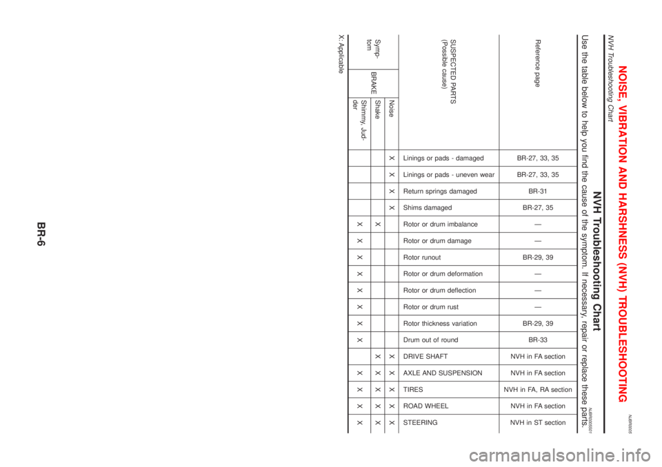
NVH Troubleshooting ChartNJBR0005S01Use the table below to help you find the cause of the symptom. If necessary, repair or replace these parts.
Reference page
BR-27, 33, 35
BR-27, 33, 35
BR-31
BR-27, 35
Ð
Ð
BR-29, 39
Ð
Ð
Ð
BR-29, 39
BR-33
NVH in FA section
NVH in FA section
NVH in FA, RA section
NVH in FA section
NVH in ST section
SUSPECTED PARTS
(Possible cause)
Linings or pads - damaged
Linings or pads - uneven wear
Return springs damaged
Shims damaged
Rotor or drum imbalance
Rotor or drum damage
Rotor runout
Rotor or drum deformation
Rotor or drum deflection
Rotor or drum rust
Rotor thickness variation
Drum out of round
DRIVE SHAFT
AXLE AND SUSPENSION
TIRES
ROAD WHEEL
STEERING
Symp-
tomBRAKENoiseXXXX XXXXX
Shake XXXXXX
Shimmy, Jud-
derXXXXXXXX XXXX
X: Applicable
NOISE, VIBRATION AND HARSHNESS (NVH) TROUBLESHOOTING
NVH Troubleshooting Chart
BR-6
Page 1722 of 2493
SBR633E
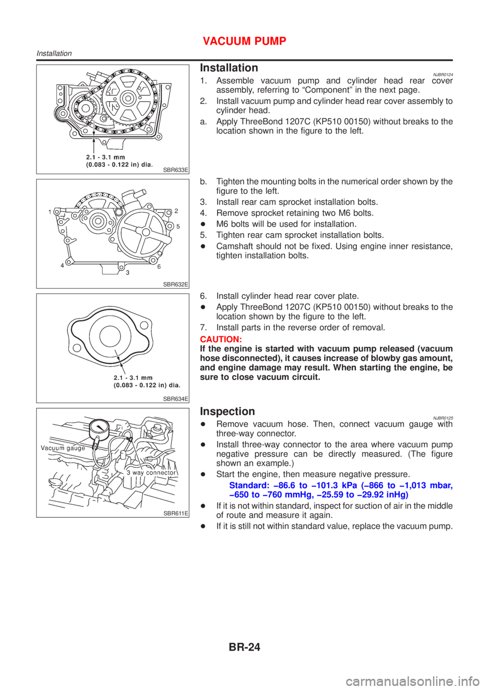
InstallationNJBR01241. Assemble vacuum pump and cylinder head rear cover
assembly, referring to ªComponentº in the next page.
2. Install vacuum pump and cylinder head rear cover assembly to
cylinder head.
a. Apply ThreeBond 1207C (KP510 00150) without breaks to the
location shown in the figure to the left.
SBR632E
b. Tighten the mounting bolts in the numerical order shown by the
figure to the left.
3. Install rear cam sprocket installation bolts.
4. Remove sprocket retaining two M6 bolts.
+M6 bolts will be used for installation.
5. Tighten rear cam sprocket installation bolts.
+Camshaft should not be fixed. Using engine inner resistance,
tighten installation bolts.
SBR634E
6. Install cylinder head rear cover plate.
+Apply ThreeBond 1207C (KP510 00150) without breaks to the
location shown by the figure to the left.
7. Install parts in the reverse order of removal.
CAUTION:
If the engine is started with vacuum pump released (vacuum
hose disconnected), it causes increase of blowby gas amount,
and engine damage may result. When starting the engine, be
sure to close vacuum circuit.
SBR611E
InspectionNJBR0125+Remove vacuum hose. Then, connect vacuum gauge with
three-way connector.
+Install three-way connector to the area where vacuum pump
negative pressure can be directly measured. (The figure
shown an example.)
+Start the engine, then measure negative pressure.
Standard: þ86.6 to þ101.3 kPa (þ866 to þ1,013 mbar,
þ650 to þ760 mmHg, þ25.59 to þ29.92 inHg)
+If it is not within standard, inspect for suction of air in the middle
of route and measure it again.
+If it is still not within standard value, replace the vacuum pump.
VACUUM PUMP
Installation
BR-24
Page 1758 of 2493
![NISSAN ALMERA N16 2001 Electronic Repair Manual SELF-DIAGNOSTIC RESULTS MODE=NJBR0093S02
Diagnostic item Diagnostic item is detected when ...Reference
Page
FR RH SENSOR
[OPEN]*1+Circuit for front right wheel sensor is open.
(An abnormally high inpu NISSAN ALMERA N16 2001 Electronic Repair Manual SELF-DIAGNOSTIC RESULTS MODE=NJBR0093S02
Diagnostic item Diagnostic item is detected when ...Reference
Page
FR RH SENSOR
[OPEN]*1+Circuit for front right wheel sensor is open.
(An abnormally high inpu](/manual-img/5/57351/w960_57351-1757.png)
SELF-DIAGNOSTIC RESULTS MODE=NJBR0093S02
Diagnostic item Diagnostic item is detected when ...Reference
Page
FR RH SENSOR
[OPEN]*1+Circuit for front right wheel sensor is open.
(An abnormally high input voltage is entered.)BR-69
FR LH SENSOR
[OPEN]*1+Circuit for front left wheel sensor is open.
(An abnormally high input voltage is entered.)BR-69
RR RH SENSOR
[OPEN]*1+Circuit for rear right sensor is open.
(An abnormally high input voltage is entered.)BR-69
RR LH SENSOR
[OPEN]*1+Circuit for rear left sensor is open.
(An abnormally high input voltage is entered.)BR-69
FR RH SENSOR
[SHORT]*1+Circuit for front right wheel sensor is shorted.
(An abnormally low input voltage is entered.)BR-69
FR LH SENSOR
[SHORT]*1+Circuit for front left wheel sensor is shorted.
(An abnormally low input voltage is entered.)BR-69
RR RH SENSOR
[SHORT]*1+Circuit for rear right sensor is shorted.
(An abnormally low input voltage is entered.)BR-69
RR LH SENSOR
[SHORT]*1+Circuit for rear left sensor is shorted.
(An abnormally low input voltage is entered.)BR-69
ABS SENSOR
[ABNORMAL SIGNAL]+Teeth damage on sensor rotor or improper installation of wheel sensor.
(Abnormal wheel sensor signal is entered.)BR-69
FR RH IN ABS SOL
[OPEN]+Circuit for front right inlet solenoid valve is open.
(An abnormally low output voltage is entered.)BR-72
FR LH IN ABS SOL
[OPEN]+Circuit for front left inlet solenoid valve is open.
(An abnormally low output voltage is entered.)BR-72
RR RH IN ABS SOL
[OPEN]+Circuit for rear right inlet solenoid valve is open.
(An abnormally low output voltage is entered.)BR-72
RR LH IN ABS SOL
[OPEN]+Circuit for rear left inlet solenoid valve is open.
(An abnormally low output voltage is entered.)BR-72
FR RH IN ABS SOL
[SHORT]+Circuit for front right inlet solenoid valve is shorted.
(An abnormally high output voltage is entered.)BR-72
FR LH IN ABS SOL
[SHORT]+Circuit for front left inlet solenoid valve is shorted.
(An abnormally high output voltage is entered.)BR-72
RR RH IN ABS SOL
[SHORT]+Circuit for rear right inlet solenoid valve is shorted.
(An abnormally high output voltage is entered.)BR-72
RR LH IN ABS SOL
[SHORT]+Circuit for rear left inlet solenoid valve is shorted.
(An abnormally high output voltage is entered.)BR-72
FR RH OUT ABS SOL
[OPEN]+Circuit for front right outlet solenoid valve is open.
(An abnormally low output voltage is entered.)BR-72
FR LH OUT ABS SOL
[OPEN]+Circuit for front left outlet solenoid valve is open.
(An abnormally low output voltage is entered.)BR-72
RR RH OUT ABS SOL
[OPEN]+Circuit for rear right outlet solenoid valve is open.
(An abnormally low output voltage is entered.)BR-72
RR LH OUT ABS SOL
[OPEN]+Circuit for rear left outlet solenoid valve is open.
(An abnormally low output voltage is entered.)BR-72
FR RH OUT ABS SOL
[SHORT]+Circuit for front right outlet solenoid valve is shorted.
(An abnormally high output voltage is entered.)BR-72
FR LH OUT ABS SOL
[SHORT]+Circuit for front left outlet solenoid valve is shorted.
(An abnormally high output voltage is entered.)BR-72
ON BOARD DIAGNOSTIC SYSTEM DESCRIPTIONABS
CONSULT-II Inspection Procedure (Cont'd)
BR-60
Page 1759 of 2493
![NISSAN ALMERA N16 2001 Electronic Repair Manual Diagnostic item Diagnostic item is detected when ...Reference
Page
RR RH OUT ABS SOL
[SHORT]+Circuit for rear right outlet solenoid valve is shorted.
(An abnormally high output voltage is entered.)BR- NISSAN ALMERA N16 2001 Electronic Repair Manual Diagnostic item Diagnostic item is detected when ...Reference
Page
RR RH OUT ABS SOL
[SHORT]+Circuit for rear right outlet solenoid valve is shorted.
(An abnormally high output voltage is entered.)BR-](/manual-img/5/57351/w960_57351-1758.png)
Diagnostic item Diagnostic item is detected when ...Reference
Page
RR RH OUT ABS SOL
[SHORT]+Circuit for rear right outlet solenoid valve is shorted.
(An abnormally high output voltage is entered.)BR-72
RR LH OUT ABS SOL
[SHORT]+Circuit for rear left outlet solenoid valve is shorted.
(An abnormally high output voltage is entered.)BR-72
ABS ACTUATOR RELAY
[ABNORMAL]+Actuator solenoid valve relay is ON, even control unit sends off signal.
+Actuator solenoid valve relay is OFF, even control unit sends on signal.BR-72
ABS MOTOR RELAY
[ABNORMAL]+Circuit for actuator motor is open or shorted.
+Actuator motor relay is stuck.BR-75
BATTERY VOLT
[ABNORMAL]+Power source voltage supplied to ABS control unit is abnormally low. BR-77
CONTROL UNIT+Function of calculation in ABS control unit has failed. BR-79
*1: Be sure to confirm the ABS warning lamp illuminates when the ignition switch is turned ON after repairing the shorted sensor circuit,
but the lamp goes out when driving the vehicle over 30 km/h (19 MPH) for one minute in accordance with SELF-DIAGNOSIS
PROCEDURE.
PBR455D
DATA MONITOR PROCEDURENJBR0093S031. Turn ignition switch OFF.
2. Connect CONSULT-II to data link connector.
3. Turn ignition switch ON.
4. Touch ªSTARTº on CONSULT-II screen.
PBR385C
5. Touch ªABSº.
PST412B
6. Touch ªDATA MONITORº.
7. Touch ªSETTINGº on ªSELECT MONITOR ITEMº screen.
8. Touch ªLONG TIMEº on ªSET RECORDING CONDº screen.
9. Touch ªSTARTº on ªSELECT MONITOR ITEMº.
ON BOARD DIAGNOSTIC SYSTEM DESCRIPTIONABS
CONSULT-II Inspection Procedure (Cont'd)
BR-61