2001 NISSAN ALMERA N16 EL page 71
[x] Cancel search: EL page 71Page 2352 of 2493
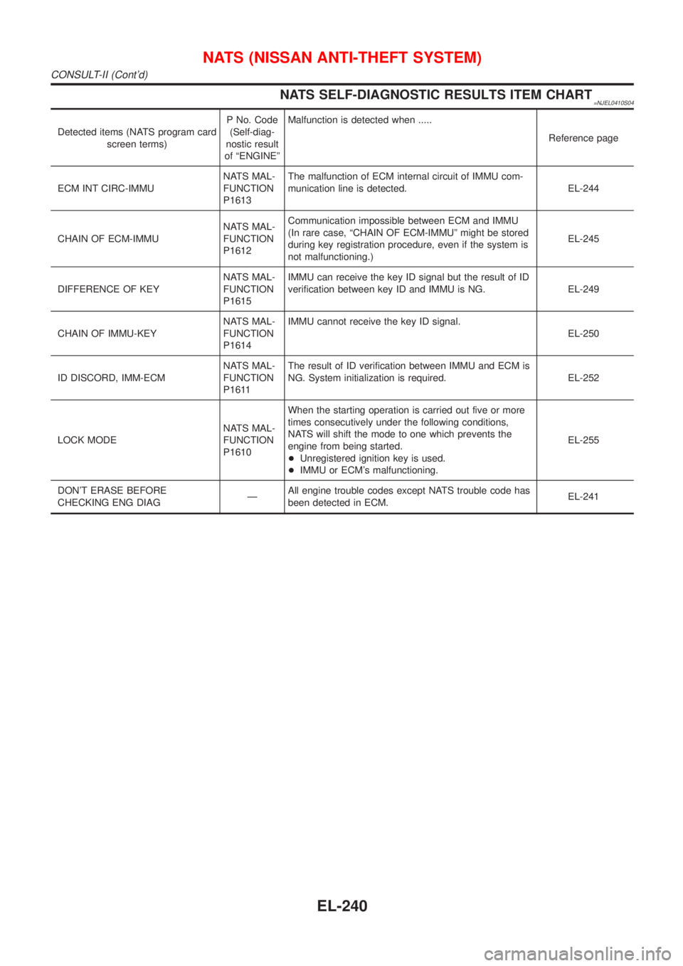
NATS SELF-DIAGNOSTIC RESULTS ITEM CHART=NJEL0410S04
Detected items (NATS program card
screen terms)P No. Code
(Self-diag-
nostic result
of ªENGINEºMalfunction is detected when .....
Reference page
ECM INT CIRC-IMMUNATS MAL-
FUNCTION
P1613The malfunction of ECM internal circuit of IMMU com-
munication line is detected. EL-244
CHAIN OF ECM-IMMUNATS MAL-
FUNCTION
P1612Communication impossible between ECM and IMMU
(In rare case, ªCHAIN OF ECM-IMMUº might be stored
during key registration procedure, even if the system is
not malfunctioning.)EL-245
DIFFERENCE OF KEYNATS MAL-
FUNCTION
P1615IMMU can receive the key ID signal but the result of ID
verification between key ID and IMMU is NG. EL-249
CHAIN OF IMMU-KEYNATS MAL-
FUNCTION
P1614IMMU cannot receive the key ID signal.
EL-250
ID DISCORD, IMM-ECMNATS MAL-
FUNCTION
P1611The result of ID verification between IMMU and ECM is
NG. System initialization is required. EL-252
LOCK MODENATS MAL-
FUNCTION
P1610When the starting operation is carried out five or more
times consecutively under the following conditions,
NATS will shift the mode to one which prevents the
engine from being started.
+Unregistered ignition key is used.
+IMMU or ECM's malfunctioning.EL-255
DON'T ERASE BEFORE
CHECKING ENG DIAGÐAll engine trouble codes except NATS trouble code has
been detected in ECM.EL-241
NATS (NISSAN ANTI-THEFT SYSTEM)
CONSULT-II (Cont'd)
EL-240
Page 2354 of 2493
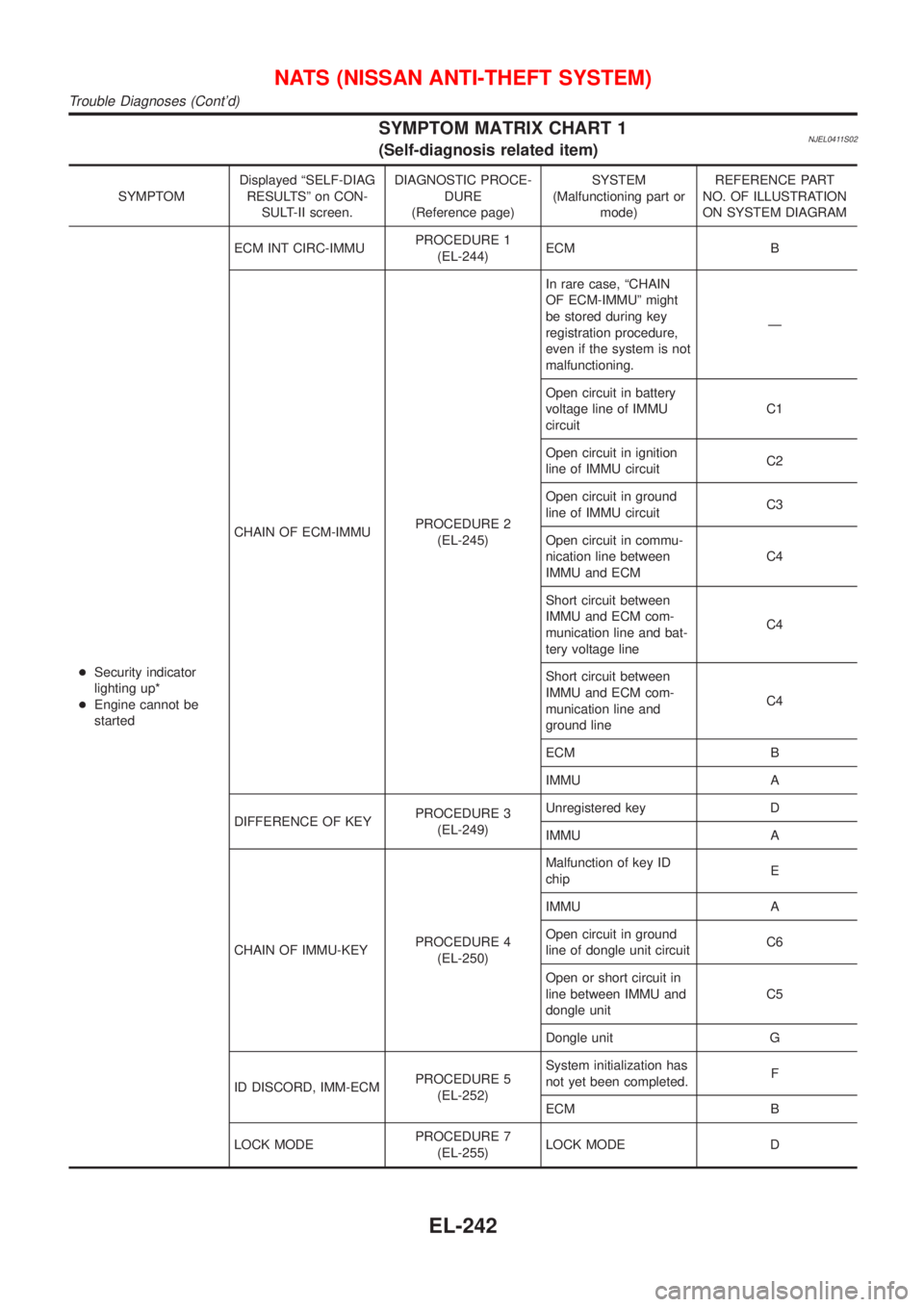
SYMPTOM MATRIX CHART 1NJEL0411S02(Self-diagnosis related item)
SYMPTOMDisplayed ªSELF-DIAG
RESULTSº on CON-
SULT-II screen.DIAGNOSTIC PROCE-
DURE
(Reference page)SYSTEM
(Malfunctioning part or
mode)REFERENCE PART
NO. OF ILLUSTRATION
ON SYSTEM DIAGRAM
+Security indicator
lighting up*
+Engine cannot be
startedECM INT CIRC-IMMUPROCEDURE 1
(EL-244)ECM B
CHAIN OF ECM-IMMUPROCEDURE 2
(EL-245)In rare case, ªCHAIN
OF ECM-IMMUº might
be stored during key
registration procedure,
even if the system is not
malfunctioning.Ð
Open circuit in battery
voltage line of IMMU
circuitC1
Open circuit in ignition
line of IMMU circuitC2
Open circuit in ground
line of IMMU circuitC3
Open circuit in commu-
nication line between
IMMU and ECMC4
Short circuit between
IMMU and ECM com-
munication line and bat-
tery voltage lineC4
Short circuit between
IMMU and ECM com-
munication line and
ground lineC4
ECM B
IMMU A
DIFFERENCE OF KEYPROCEDURE 3
(EL-249)Unregistered key D
IMMU A
CHAIN OF IMMU-KEYPROCEDURE 4
(EL-250)Malfunction of key ID
chipE
IMMU A
Open circuit in ground
line of dongle unit circuitC6
Open or short circuit in
line between IMMU and
dongle unitC5
Dongle unit G
ID DISCORD, IMM-ECMPROCEDURE 5
(EL-252)System initialization has
not yet been completed.F
ECM B
LOCK MODEPROCEDURE 7
(EL-255)LOCK MODE D
NATS (NISSAN ANTI-THEFT SYSTEM)
Trouble Diagnoses (Cont'd)
EL-242
Page 2355 of 2493
SYMPTOMDisplayed ªSELF-DIAG
RESULTSº on CON-
SULT-II screen.DIAGNOSTIC PROCE-
DURE
(Reference page)SYSTEM
(Malfunctioning part or
mode)REFERENCE PART
NO. OF ILLUSTRATION
ON SYSTEM DIAGRAM
+MIL staying ON
+Security indicator
lighting up*DON'T ERASE
BEFORE CHECKING
ENG DIAGWORK FLOW
(EL-241)Engine trouble data and
NATS trouble data have
been detected in ECMÐ
*: When NATS detects trouble, the security indicator lights up while ignition key is in the ªONº position.
*: When the vehicle is equipped with a dongle unit (RHD models for Europe), the security indicator blinks 6 times just after the ignition
switch is turned to ON. Then the security indicator lights up while the ignition key is in the ªONº position.
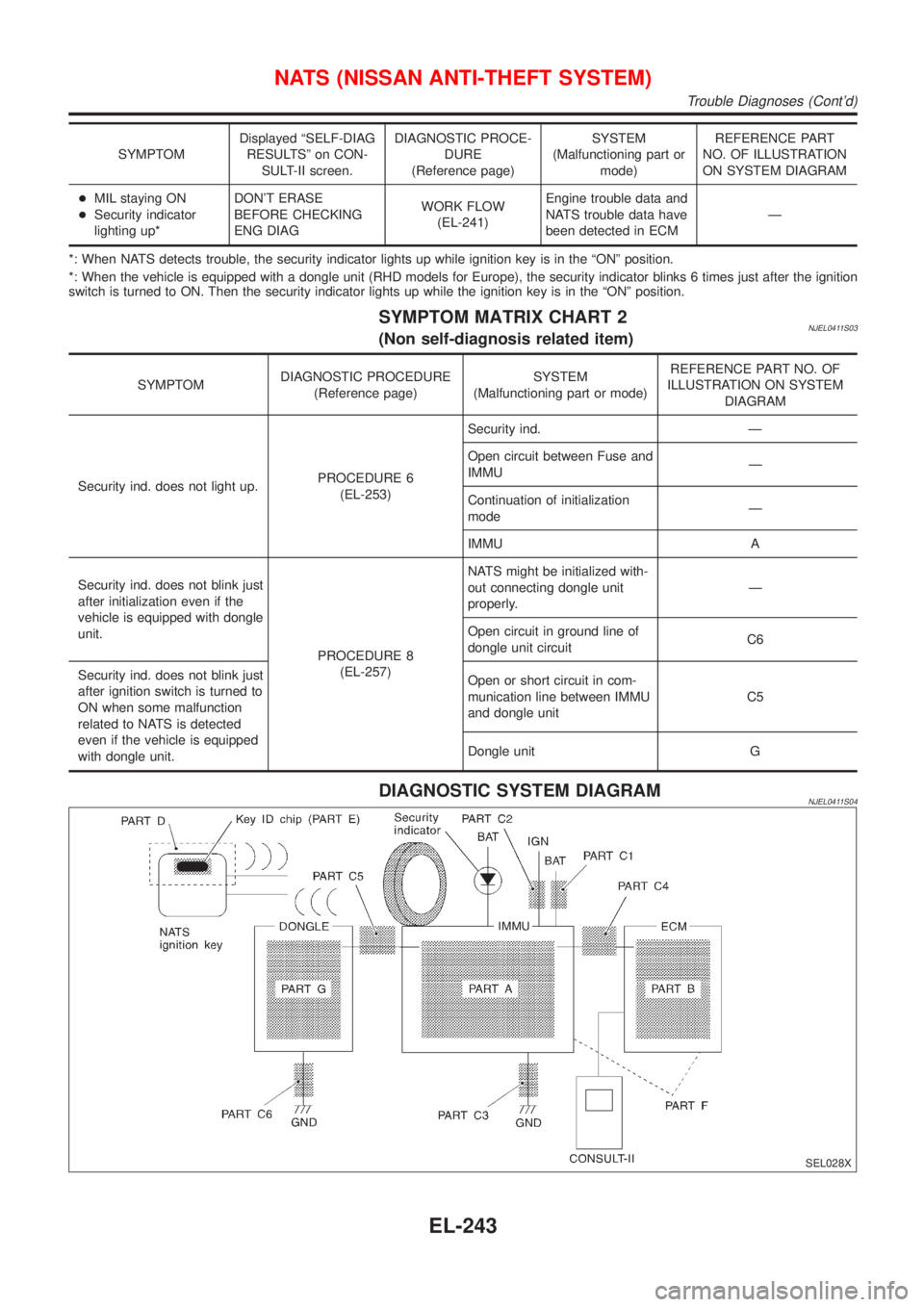
SYMPTOM MATRIX CHART 2NJEL0411S03(Non self-diagnosis related item)
SYMPTOMDIAGNOSTIC PROCEDURE
(Reference page)SYSTEM
(Malfunctioning part or mode)REFERENCE PART NO. OF
ILLUSTRATION ON SYSTEM
DIAGRAM
Security ind. does not light up.PROCEDURE 6
(EL-253)Security ind. Ð
Open circuit between Fuse and
IMMUÐ
Continuation of initialization
modeÐ
IMMU A
Security ind. does not blink just
after initialization even if the
vehicle is equipped with dongle
unit.
PROCEDURE 8
(EL-257)NATS might be initialized with-
out connecting dongle unit
properly.Ð
Open circuit in ground line of
dongle unit circuitC6
Security ind. does not blink just
after ignition switch is turned to
ON when some malfunction
related to NATS is detected
even if the vehicle is equipped
with dongle unit.Open or short circuit in com-
munication line between IMMU
and dongle unitC5
Dongle unit G
DIAGNOSTIC SYSTEM DIAGRAMNJEL0411S04
SEL028X
NATS (NISSAN ANTI-THEFT SYSTEM)
Trouble Diagnoses (Cont'd)
EL-243
Page 2390 of 2493
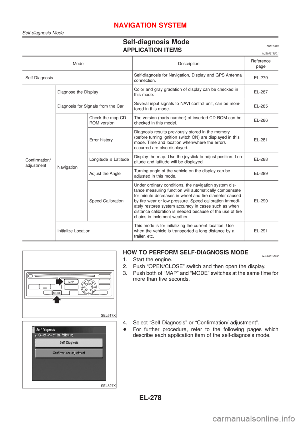
Self-diagnosis ModeNJEL0519APPLICATION ITEMSNJEL0519S01
Mode DescriptionReference
page
Self DiagnosisSelf-diagnosis for Navigation, Display and GPS Antenna
connection.EL-279
Confirmation/
adjustmentDiagnose the DisplayColor and gray gradation of display can be checked in
this mode.EL-287
Diagnosis for Signals from the CarSeveral input signals to NAVI control unit, can be moni-
tored in this mode.EL-285
NavigationCheck the map CD-
ROM versionThe version (parts number) of inserted CD-ROM can be
checked in this model.EL-286
Error historyDiagnosis results previously stored in the memory
(before turning ignition switch ON) are displayed in this
mode. Time and location when/where the errors
occurred are also displayed.EL-281
Longitude & LatitudeDisplay the map. Use the joystick to adjust position. Lon-
gitude and latitude will be displayed.EL-288
Adjust the AngleTurning angle of the vehicle on the display can be
adjusted in this mode.EL-289
Speed CalibrationUnder ordinary conditions, the navigation system dis-
tance measuring function will automatically compensate
for minute decreases in wheel and tire diameter caused
by tire wear or low pressure. Speed calibration immedi-
ately restores system accuracy in cases such as when
distance calibration is needed because of the use of tire
chains in inclement weather.EL-290
Initialize LocationThis mode is for initializing the current location. Use
when the vehicle is transported a long distance by a
trailer, etc.EL-291
MODEMAP
SEL617X
HOW TO PERFORM SELF-DIAGNOSIS MODENJEL0519S021. Start the engine.
2. Push ªOPEN/CLOSEº switch and then open the display.
3. Push both of ªMAPº and ªMODEº switches at the same time for
more than five seconds.
SEL527X
4. Select ªSelf Diagnosisº or ªConfirmation/ adjustmentº.
+For further procedure, refer to the following pages which
describe each application item of the self-diagnosis mode.
NAVIGATION SYSTEM
Self-diagnosis Mode
EL-278
Page 2395 of 2493
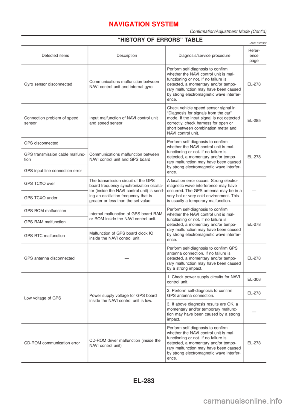
ªHISTORY OF ERRORSº TABLE=NJEL0520S02
Detected items Description Diagnosis/service procedureRefer-
ence
page
Gyro sensor disconnectedCommunications malfunction between
NAVI control unit and internal gyroPerform self-diagnosis to confirm
whether the NAVI control unit is mal-
functioning or not. If no failure is
detected, a momentary and/or tempo-
rary malfunction may have been caused
by strong electromagnetic wave interfer-
ence.EL-278
Connection problem of speed
sensorInput malfunction of NAVI control unit
and speed sensorCheck vehicle speed sensor signal in
ªDiagnosis for signals from the carº
mode. If the input signal is not detected
correctly, check harness for open or
short between combination meter and
NAVI control unit.EL-285
GPS disconnected
Communications malfunction between
NAVI control unit and GPS boardPerform self-diagnosis to confirm
whether the NAVI control unit is mal-
functioning or not. If no failure is
detected, a momentary and/or tempo-
rary malfunction may have been caused
by strong electromagnetic wave interfer-
ence.EL-278 GPS transmission cable malfunc-
tion
GPS input line connection error
GPS TCXO overThe transmission circuit of the GPS
board frequency synchronization oscilla-
tor (inside the NAVI control unit) is send-
ing an oscillation frequency that is
greater or less than the set value.A location error occurs. Strong electro-
magnetic wave interference may have
occurred. The GPS antenna may be in a
very hot or very cold environment. This
is usually a temporary malfunction.Ð
GPS TCXO under
GPS ROM malfunction
Internal malfunction of GPS board RAM
or ROM inside the NAVI control unit.Perform self-diagnosis to confirm
whether the NAVI control unit is mal-
functioning or not. If no failure is
detected, a momentary and/or tempo-
rary malfunction may have been caused
by strong electromagnetic wave interfer-
ence.EL-278 GPS RAM malfunction
GPS RTC malfunctionMalfunction of GPS board clock IC
inside the NAVI control unit.
GPS antenna disconnected ÐPerform self-diagnosis to confirm GPS
antenna connection. If no failure is
detected, a momentary and/or tempo-
rary malfunction may have been caused
by a strong impact.EL-278
Low voltage of GPSPower supply voltage for GPS board
inside the NAVI control unit is low.1. Check power supply circuits for NAVI
control unit.EL-306
2. Perform self-diagnosis to confirm
GPS antenna connection.EL-278
3. If above diagnosis results are OK, a
momentary and/or temporary malfunc-
tion may have been caused by a strong
impact.Ð
CD-ROM communication errorCD-ROM driver malfunction (inside the
NAVI control unit)Perform self-diagnosis to confirm
whether the NAVI control unit is mal-
functioning or not. If no failure is
detected, a momentary and/or tempo-
rary malfunction may have been caused
by strong electromagnetic wave interfer-
ence.EL-278
NAVIGATION SYSTEM
Confirmation/Adjustment Mode (Cont'd)
EL-283
Page 2396 of 2493
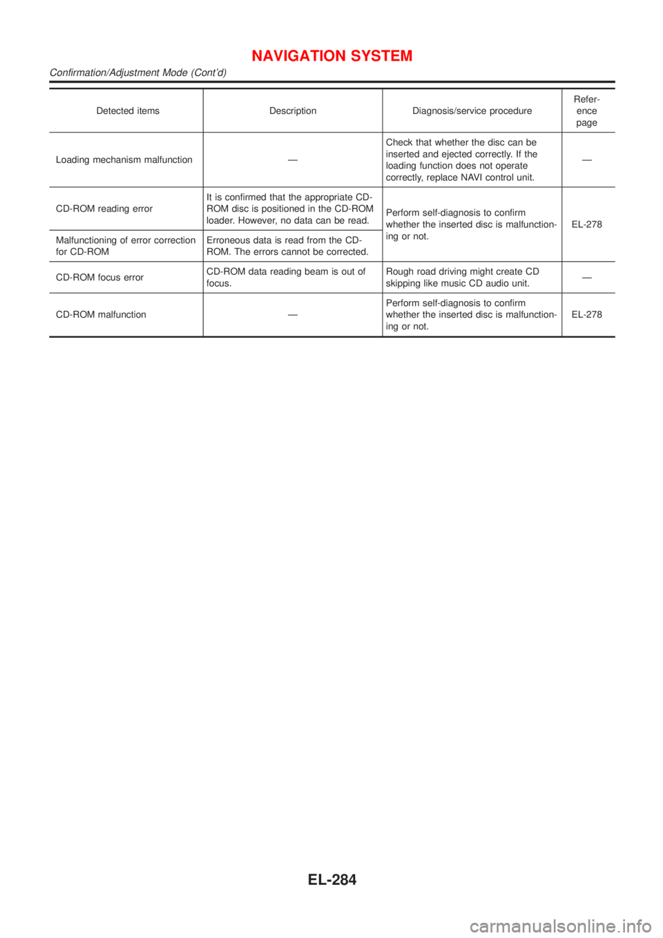
Detected items Description Diagnosis/service procedureRefer-
ence
page
Loading mechanism malfunction ÐCheck that whether the disc can be
inserted and ejected correctly. If the
loading function does not operate
correctly, replace NAVI control unit.Ð
CD-ROM reading errorIt is confirmed that the appropriate CD-
ROM disc is positioned in the CD-ROM
loader. However, no data can be read.Perform self-diagnosis to confirm
whether the inserted disc is malfunction-
ing or not.EL-278
Malfunctioning of error correction
for CD-ROMErroneous data is read from the CD-
ROM. The errors cannot be corrected.
CD-ROM focus errorCD-ROM data reading beam is out of
focus.Rough road driving might create CD
skipping like music CD audio unit.Ð
CD-ROM malfunction ÐPerform self-diagnosis to confirm
whether the inserted disc is malfunction-
ing or not.EL-278
NAVIGATION SYSTEM
Confirmation/Adjustment Mode (Cont'd)
EL-284
Page 2405 of 2493
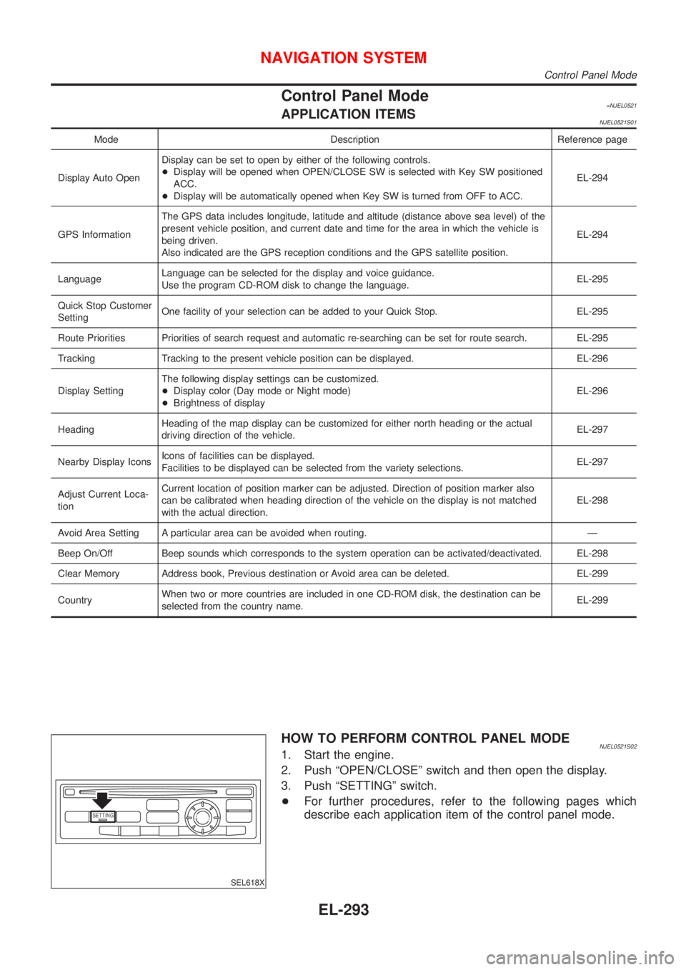
Control Panel Mode=NJEL0521APPLICATION ITEMSNJEL0521S01
Mode Description Reference page
Display Auto OpenDisplay can be set to open by either of the following controls.
+Display will be opened when OPEN/CLOSE SW is selected with Key SW positioned
ACC.
+Display will be automatically opened when Key SW is turned from OFF to ACC.EL-294
GPS InformationThe GPS data includes longitude, latitude and altitude (distance above sea level) of the
present vehicle position, and current date and time for the area in which the vehicle is
being driven.
Also indicated are the GPS reception conditions and the GPS satellite position.EL-294
LanguageLanguage can be selected for the display and voice guidance.
Use the program CD-ROM disk to change the language.EL-295
Quick Stop Customer
SettingOne facility of your selection can be added to your Quick Stop. EL-295
Route Priorities Priorities of search request and automatic re-searching can be set for route search. EL-295
Tracking Tracking to the present vehicle position can be displayed. EL-296
Display SettingThe following display settings can be customized.
+Display color (Day mode or Night mode)
+Brightness of displayEL-296
HeadingHeading of the map display can be customized for either north heading or the actual
driving direction of the vehicle.EL-297
Nearby Display IconsIcons of facilities can be displayed.
Facilities to be displayed can be selected from the variety selections.EL-297
Adjust Current Loca-
tionCurrent location of position marker can be adjusted. Direction of position marker also
can be calibrated when heading direction of the vehicle on the display is not matched
with the actual direction.EL-298
Avoid Area Setting A particular area can be avoided when routing. Ð
Beep On/Off Beep sounds which corresponds to the system operation can be activated/deactivated. EL-298
Clear Memory Address book, Previous destination or Avoid area can be deleted. EL-299
CountryWhen two or more countries are included in one CD-ROM disk, the destination can be
selected from the country name.EL-299
SETTING
SEL618X
HOW TO PERFORM CONTROL PANEL MODENJEL0521S021. Start the engine.
2. Push ªOPEN/CLOSEº switch and then open the display.
3. Push ªSETTINGº switch.
+For further procedures, refer to the following pages which
describe each application item of the control panel mode.
NAVIGATION SYSTEM
Control Panel Mode
EL-293
Page 2415 of 2493
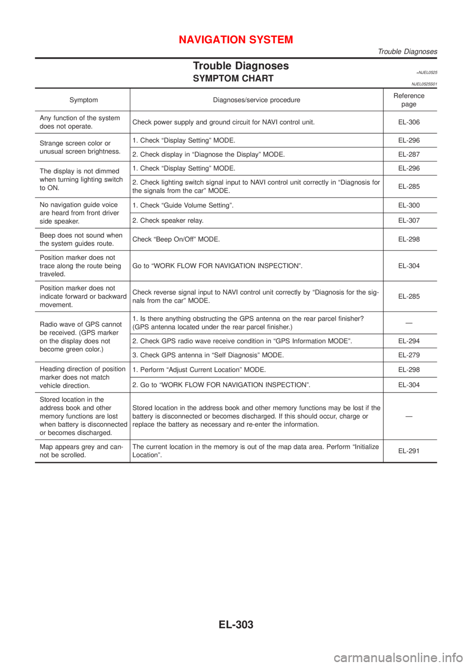
Trouble Diagnoses=NJEL0525SYMPTOM CHARTNJEL0525S01
Symptom Diagnoses/service procedureReference
page
Any function of the system
does not operate.Check power supply and ground circuit for NAVI control unit. EL-306
Strange screen color or
unusual screen brightness.1. Check ªDisplay Settingº MODE. EL-296
2. Check display in ªDiagnose the Displayº MODE. EL-287
The display is not dimmed
when turning lighting switch
to ON.1. Check ªDisplay Settingº MODE. EL-296
2. Check lighting switch signal input to NAVI control unit correctly in ªDiagnosis for
the signals from the carº MODE.EL-285
No navigation guide voice
are heard from front driver
side speaker.1. Check ªGuide Volume Settingº. EL-300
2. Check speaker relay. EL-307
Beep does not sound when
the system guides route.Check ªBeep On/Offº MODE. EL-298
Position marker does not
trace along the route being
traveled.Go to ªWORK FLOW FOR NAVIGATION INSPECTIONº. EL-304
Position marker does not
indicate forward or backward
movement.Check reverse signal input to NAVI control unit correctly by ªDiagnosis for the sig-
nals from the carº MODE.EL-285
Radio wave of GPS cannot
be received. (GPS marker
on the display does not
become green color.)1. Is there anything obstructing the GPS antenna on the rear parcel finisher?
(GPS antenna located under the rear parcel finisher.)Ð
2. Check GPS radio wave receive condition in ªGPS Information MODEº. EL-294
3. Check GPS antenna in ªSelf Diagnosisº MODE. EL-279
Heading direction of position
marker does not match
vehicle direction.1. Perform ªAdjust Current Locationº MODE. EL-298
2. Go to ªWORK FLOW FOR NAVIGATION INSPECTIONº. EL-304
Stored location in the
address book and other
memory functions are lost
when battery is disconnected
or becomes discharged.Stored location in the address book and other memory functions may be lost if the
battery is disconnected or becomes discharged. If this should occur, charge or
replace the battery as necessary and re-enter the information.Ð
Map appears grey and can-
not be scrolled.The current location in the memory is out of the map data area. Perform ªInitialize
Locationº.EL-291
NAVIGATION SYSTEM
Trouble Diagnoses
EL-303