2001 NISSAN ALMERA N16 Starting
[x] Cancel search: StartingPage 1283 of 2493
Cruise Test Ð Part 2=NJAT0028S0405
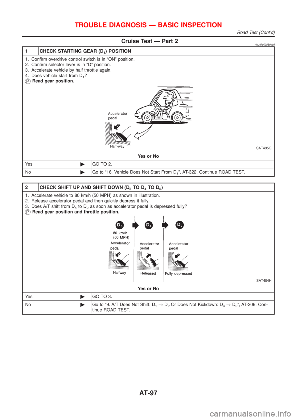
1 CHECK STARTING GEAR (D1) POSITION
1. Confirm overdrive control switch is in ªONº position.
2. Confirm selector lever is in ªDº position.
3. Accelerate vehicle by half throttle again.
4. Does vehicle start from D
1?
Read gear position.
SAT495G
YesorNo
Ye s©GO TO 2.
No©Go to ª16. Vehicle Does Not Start From D
1º, AT-322. Continue ROAD TEST.
2 CHECK SHIFT UP AND SHIFT DOWN (D3TO D4TO D2)
1. Accelerate vehicle to 80 km/h (50 MPH) as shown in illustration.
2. Release accelerator pedal and then quickly depress it fully.
3. Does A/T shift from D
4to D2as soon as accelerator pedal is depressed fully?
Read gear position and throttle position.
SAT404H
YesorNo
Ye s©GO TO 3.
No©Go to ª9. A/T Does Not Shift: D
1®D2Or Does Not Kickdown: D4®D2º, AT-306. Con-
tinue ROAD TEST.
TROUBLE DIAGNOSIS Ð BASIC INSPECTION
Road Test (Cont'd)
AT-97
Page 1289 of 2493
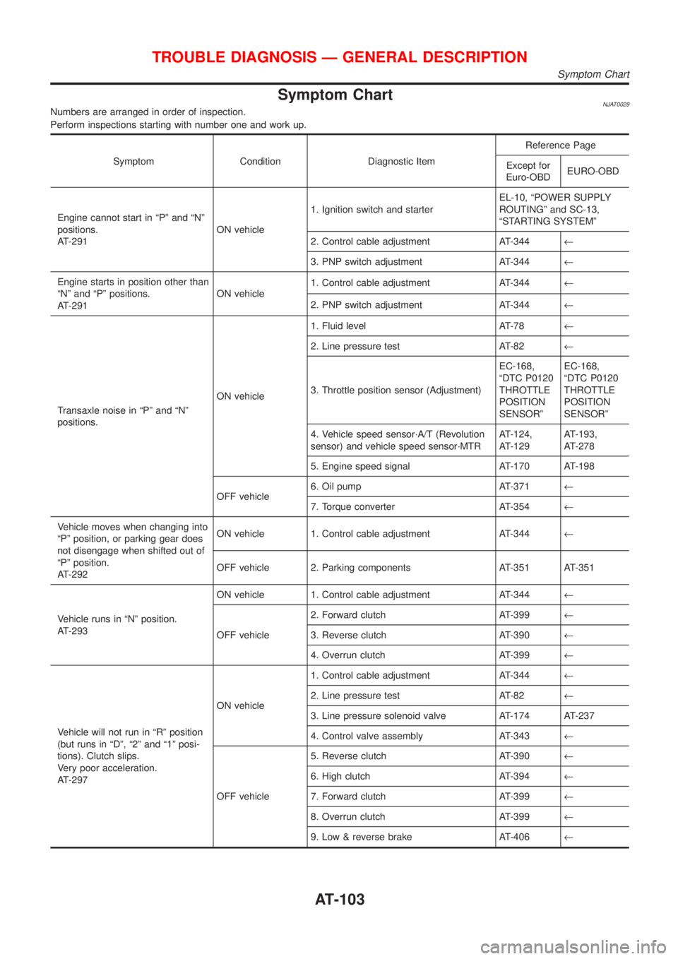
Symptom ChartNJAT0029Numbers are arranged in order of inspection.
Perform inspections starting with number one and work up.
Symptom Condition Diagnostic ItemReference Page
Except for
Euro-OBDEURO-OBD
Engine cannot start in ªPº and ªNº
positions.
AT-291ON vehicle1. Ignition switch and starterEL-10, ªPOWER SUPPLY
ROUTINGº and SC-13,
ªSTARTING SYSTEMº
2. Control cable adjustment AT-344¬
3. PNP switch adjustment AT-344¬
Engine starts in position other than
ªNº and ªPº positions.
AT-291ON vehicle1. Control cable adjustment AT-344¬
2. PNP switch adjustment AT-344¬
Transaxle noise in ªPº and ªNº
positions.ON vehicle1. Fluid level AT-78¬
2. Line pressure test AT-82¬
3. Throttle position sensor (Adjustment)EC-168,
ªDTC P0120
THROTTLE
POSITION
SENSORºEC-168,
ªDTC P0120
THROTTLE
POSITION
SENSORº
4. Vehicle speed sensor´A/T (Revolution
sensor) and vehicle speed sensor´MTRAT-124,
AT-129AT-193,
AT-278
5. Engine speed signal AT-170 AT-198
OFF vehicle6. Oil pump AT-371¬
7. Torque converter AT-354¬
Vehicle moves when changing into
ªPº position, or parking gear does
not disengage when shifted out of
ªPº position.
AT-292ON vehicle 1. Control cable adjustment AT-344¬
OFF vehicle 2. Parking components AT-351 AT-351
Vehicle runs in ªNº position.
AT-293ON vehicle 1. Control cable adjustment AT-344¬
OFF vehicle2. Forward clutch AT-399¬
3. Reverse clutch AT-390¬
4. Overrun clutch AT-399¬
Vehicle will not run in ªRº position
(but runs in ªDº, ª2º and ª1º posi-
tions). Clutch slips.
Very poor acceleration.
AT-297ON vehicle1. Control cable adjustment AT-344¬
2. Line pressure test AT-82¬
3. Line pressure solenoid valve AT-174 AT-237
4. Control valve assembly AT-343¬
OFF vehicle5. Reverse clutch AT-390¬
6. High clutch AT-394¬
7. Forward clutch AT-399¬
8. Overrun clutch AT-399¬
9. Low & reverse brake AT-406¬
TROUBLE DIAGNOSIS Ð GENERAL DESCRIPTION
Symptom Chart
AT-103
Page 1291 of 2493
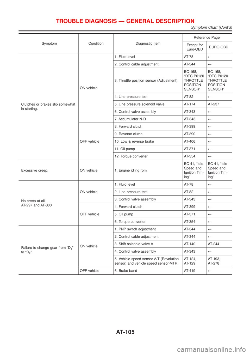
Symptom Condition Diagnostic ItemReference Page
Except for
Euro-OBDEURO-OBD
Clutches or brakes slip somewhat
in starting.ON vehicle1. Fluid level AT-78¬
2. Control cable adjustment AT-344¬
3. Throttle position sensor (Adjustment)EC-168,
ªDTC P0120
THROTTLE
POSITION
SENSORºEC-168,
ªDTC P0120
THROTTLE
POSITION
SENSORº
4. Line pressure test AT-82¬
5. Line pressure solenoid valve AT-174 AT-237
6. Control valve assembly AT-343¬
7. Accumulator N-D AT-343¬
OFF vehicle8. Forward clutch AT-399¬
9. Reverse clutch AT-390¬
10. Low & reverse brake AT-406¬
11. Oil pump AT-371¬
12. Torque converter AT-354¬
Excessive creep. ON vehicle 1. Engine idling rpmEC-41, ªIdle
Speed and
Ignition Tim-
ingºEC-41, ªIdle
Speed and
Ignition Tim-
ingº
No creep at all.
AT-297 and AT-300ON vehicle1. Fluid level AT-78¬
2. Line pressure test AT-82¬
3. Control valve assembly AT-343¬
OFF vehicle4. Forward clutch AT-399¬
5. Oil pump AT-371¬
6. Torque converter AT-354¬
Failure to change gear from ªD
1º
to ªD
2º.ON vehicle1. PNP switch adjustment AT-344¬
2. Control cable adjustment AT-344¬
3. Shift solenoid valve A AT-140 AT-244
4. Control valve assembly AT-343¬
5. Vehicle speed sensor´A/T (Revolution
sensor) and vehicle speed sensor´MTRAT-124,
AT-129AT-193,
AT-278
OFF vehicle 6. Brake band AT-419¬
TROUBLE DIAGNOSIS Ð GENERAL DESCRIPTION
Symptom Chart (Cont'd)
AT-105
Page 1478 of 2493
3 CHECK STARTING SYSTEM
Check starting system. Refer to SC-13, ªSTARTING SYSTEMº.
OK or NG
OK©INSPECTION END
NG©Repair or replace damaged parts.
3. In ªPº Position, Vehicle Moves Forward Or
Backward When Pushed
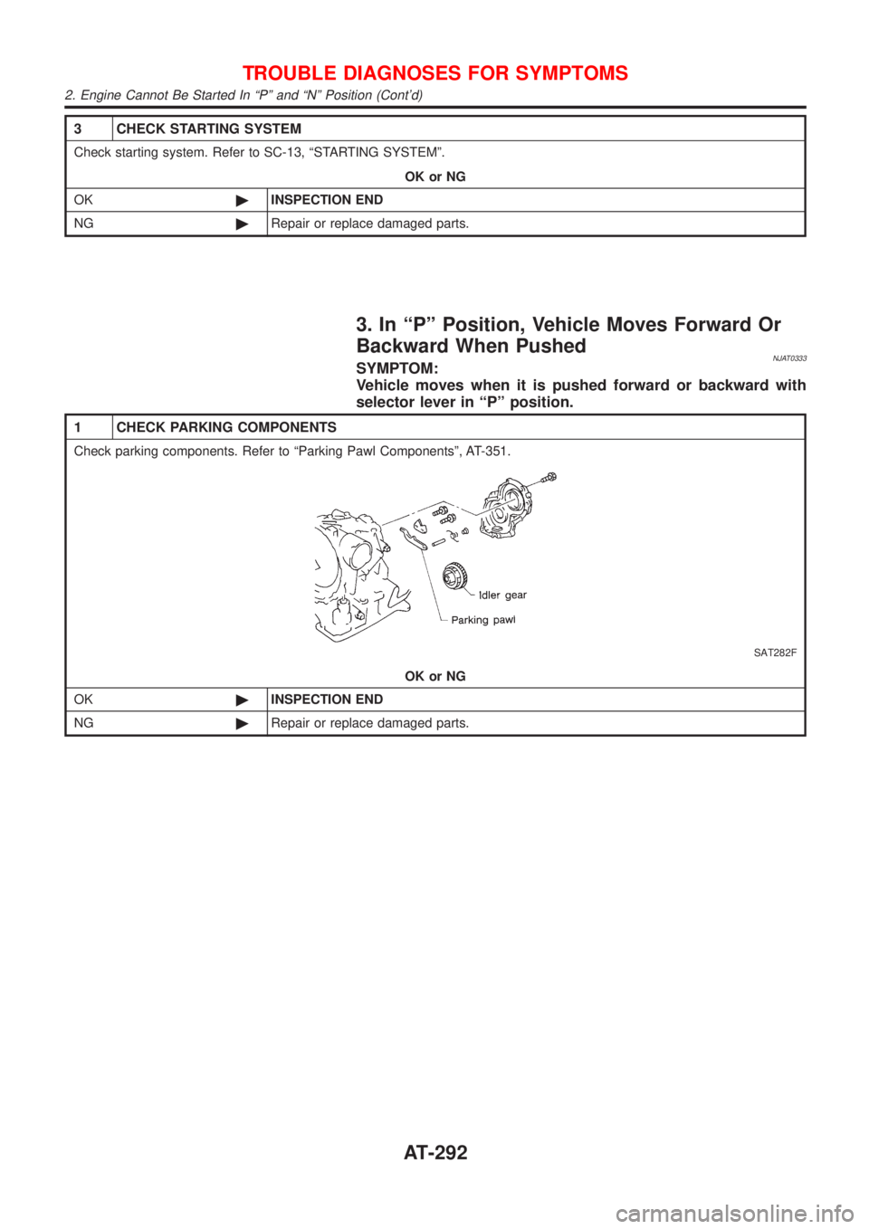
NJAT0333SYMPTOM:
Vehicle moves when it is pushed forward or backward with
selector lever in ªPº position.
1 CHECK PARKING COMPONENTS
Check parking components. Refer to ªParking Pawl Componentsº, AT-351.
SAT282F
OK or NG
OK©INSPECTION END
NG©Repair or replace damaged parts.
TROUBLE DIAGNOSES FOR SYMPTOMS
2. Engine Cannot Be Started In ªPº and ªNº Position (Cont'd)
AT-292
Page 1722 of 2493
SBR633E
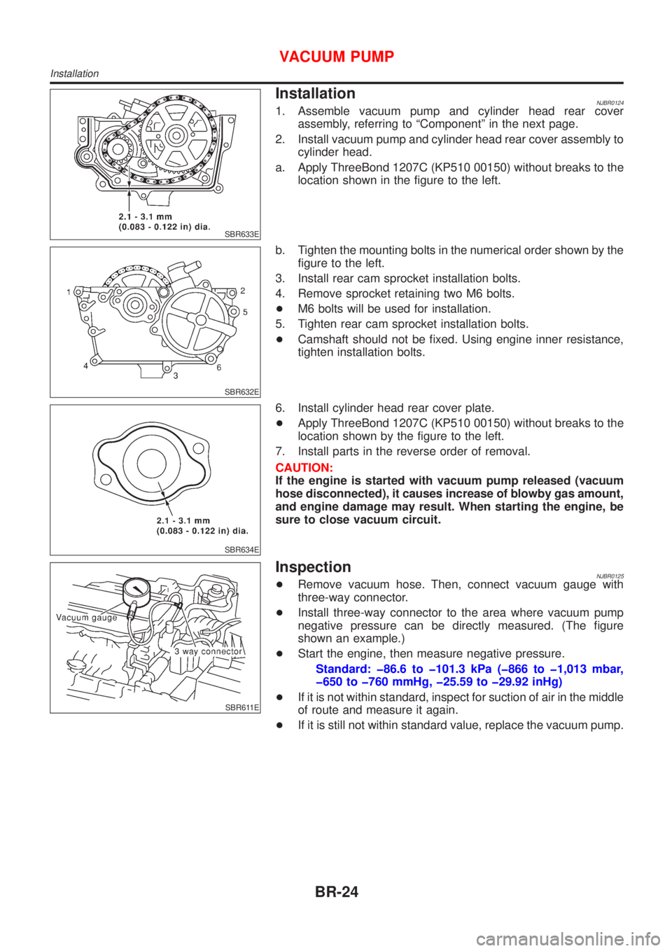
InstallationNJBR01241. Assemble vacuum pump and cylinder head rear cover
assembly, referring to ªComponentº in the next page.
2. Install vacuum pump and cylinder head rear cover assembly to
cylinder head.
a. Apply ThreeBond 1207C (KP510 00150) without breaks to the
location shown in the figure to the left.
SBR632E
b. Tighten the mounting bolts in the numerical order shown by the
figure to the left.
3. Install rear cam sprocket installation bolts.
4. Remove sprocket retaining two M6 bolts.
+M6 bolts will be used for installation.
5. Tighten rear cam sprocket installation bolts.
+Camshaft should not be fixed. Using engine inner resistance,
tighten installation bolts.
SBR634E
6. Install cylinder head rear cover plate.
+Apply ThreeBond 1207C (KP510 00150) without breaks to the
location shown by the figure to the left.
7. Install parts in the reverse order of removal.
CAUTION:
If the engine is started with vacuum pump released (vacuum
hose disconnected), it causes increase of blowby gas amount,
and engine damage may result. When starting the engine, be
sure to close vacuum circuit.
SBR611E
InspectionNJBR0125+Remove vacuum hose. Then, connect vacuum gauge with
three-way connector.
+Install three-way connector to the area where vacuum pump
negative pressure can be directly measured. (The figure
shown an example.)
+Start the engine, then measure negative pressure.
Standard: þ86.6 to þ101.3 kPa (þ866 to þ1,013 mbar,
þ650 to þ760 mmHg, þ25.59 to þ29.92 inHg)
+If it is not within standard, inspect for suction of air in the middle
of route and measure it again.
+If it is still not within standard value, replace the vacuum pump.
VACUUM PUMP
Installation
BR-24
Page 1799 of 2493

SST834-I
Checking Hydraulic SystemNJST0016Before starting, check belt tension, driving pulley and tire pressure.
1. Set Tool. Open shut-off valve. Then bleed air. Refer to ªBleed-
ing Hydraulic Systemº, ST-8.
2. Run engine at idle speed or 1,000 rpm.
Make sure temperature of fluid in tank rises to 60 to 80ÉC (140
to 176ÉF).
WARNING:
Warm up engine with shut-off valve fully opened. If engine is
started with shut-off valve closed, fluid pressure in oil pump
increases to maximum. This will raise oil temperature abnor-
mally.
3. Check pressure with steering wheel fully turned to left and right
positions with engine idling at 1,000 rpm.
CAUTION:
Do not hold the steering wheel in a locked position for more
than 15 seconds.
Oil pump maximum standard pressure:
QG15, 18 engine
8,600 - 9,200 kPa (86.0 - 92.0 bar, 88.7 - 93.8
kg/cm
2, 1,247 - 1,334 psi)
YD22 engine
8,800 - 9,400 kPa (88.0 - 94.0 bar, 88.7 - 95.8
kg/cm
2, 1,261 - 1,362 psi)
+If pressure reaches maximum operating pressure, system is
OK.
+If pressure increases above maximum operating pressure,
check power steering pump flow control valve. Refer to ST-25.
4. If power steering pressure is below the maximum operating
pressure, slowly close shut-off valve and check pressure
again.
CAUTION:
Do not close shut-off valve for more than 15 seconds.
+If pressure increases to maximum operating pressure, gear is
damaged. Refer to ªRemoval and Installationº, ST-16.
+If pressure remains below maximum operating pressure, pump
is damaged. Refer to ªDisassemblyº, ST-26.
5. After checking hydraulic system, remove Tool and add fluid as
necessary. Then completely bleed air out of system. Refer to
ST-8.
ON-VEHICLE SERVICE
Checking Hydraulic System
ST-9
Page 2077 of 2493
STARTING & CHARGING SYSTEMS
SECTION
SC
CONTENTS
PRECAUTIONS...............................................................2
Supplemental Restraint System (SRS)²AIR
BAG²and²SEAT BELT PRE-TENSIONER²...............2
Wiring Diagrams and Trouble Diagnoses....................2
BATTERY.........................................................................3
How to Handle Battery ................................................3
METHODS OF PREVENTING OVER-DISCHARGE......3
CHECKING ELECTROLYTE LEVEL............................3
SPECIFIC GRAVITY CHECK......................................4
Battery Test and Charging Chart .................................6
CHART I...................................................................6
CHART II..................................................................7
A: SLOW CHARGE....................................................8
B: STANDARD CHARGE..........................................10
C: QUICK CHARGE................................................. 11
STARTING SYSTEM.....................................................13
System Description ....................................................13
M/T MODELS..........................................................13
A/T MODELS...........................................................13
Wiring Diagram - START -.........................................14
Trouble Diagnoses.....................................................15
Construction ...............................................................16
Removal and Installation ...........................................19
REMOVAL...............................................................19
INSTALLATION........................................................19
Inspection...................................................................19
MAGNETIC SWITCH CHECK...................................19
PINION/CLUTCH CHECK.........................................19
BRUSH CHECK.......................................................20
YOKE CHECK.........................................................21
ARMATURE CHECK................................................21
Assembly ...................................................................22
PINION PROTRUSION LENGTH ADJUSTMENT........22
CHARGING SYSTEM....................................................24
System Description ....................................................24
Wiring Diagram - CHARGE -.....................................25
Trouble Diagnoses.....................................................26
WITH IC REGULATOR.............................................26
MALFUNCTION INDICATOR....................................26
Construction ...............................................................27
Removal and Installation ...........................................30
REMOVAL (QG ENGINE).........................................30
REMOVAL (YD ENGINE)..........................................30
INSTALLATION........................................................31
Disassembly...............................................................31
REAR COVER.........................................................31
REAR BEARING......................................................31
Inspection...................................................................31
ROTOR CHECK......................................................31
BRUSH CHECK.......................................................32
STATOR CHECK.....................................................32
Assembly ...................................................................32
RING FITTING IN REAR BEARING...........................32
REAR COVER INSTALLATION.................................33
SERVICE DATA AND SPECIFICATIONS (SDS).........34
Battery........................................................................34
Starter ........................................................................34
Alternator ...................................................................35
Page 2085 of 2493
![NISSAN ALMERA N16 2001 Electronic Repair Manual Fig. 2 INITIAL CHARGING CURRENT SETTING (Slow charge)
CON-
VERTED
SPECIFIC
GRAVITYBATTERY TYPE
28B19R(L)
34B19R(L)
46B24R(L)
55B24R(L)
50D23R(L)
55D23R(L)
025 [YUASA type code]
027 [YUASA type code]
6 NISSAN ALMERA N16 2001 Electronic Repair Manual Fig. 2 INITIAL CHARGING CURRENT SETTING (Slow charge)
CON-
VERTED
SPECIFIC
GRAVITYBATTERY TYPE
28B19R(L)
34B19R(L)
46B24R(L)
55B24R(L)
50D23R(L)
55D23R(L)
025 [YUASA type code]
027 [YUASA type code]
6](/manual-img/5/57351/w960_57351-2084.png)
Fig. 2 INITIAL CHARGING CURRENT SETTING (Slow charge)
CON-
VERTED
SPECIFIC
GRAVITYBATTERY TYPE
28B19R(L)
34B19R(L)
46B24R(L)
55B24R(L)
50D23R(L)
55D23R(L)
025 [YUASA type code]
027 [YUASA type code]
65D26R(L)
80D26R(L)
063 [YUASA type code]
067 [YUASA type code]
096 [YUASA type code]
75D31R(L)
95D31R(L)
115D31R(L)
110D26R(L)
95E41R(L)
065 [YUASA type code]
075 [YUASA type code]
096L [YUASA type code]
010S [YUASA type code]
130E41R(L)
Below 1.100 4.0 (A) 5.0 (A) 7.0 (A) 8.0 (A)8.5
(A)9.0
(A)10.0 (A) 11.0 (A)14.0
(A)
+Check battery type and determine the specified current using the table shown above.
+After starting charging, adjustment of charging current is not necessary.
Fig. 3 ADDITIONAL CHARGE (Slow charge)
SEL757W
*: SC-7
CAUTION:
+Set charging current to value specified in Fig. 2. If charger is not capable of producing specified
current value, set its charging current as close to that value as possible.
+Keep battery away from open flame while it is being charged.
+When connecting charger, connect leads first, then turn on charger. Do not turn on charger first,
as this may cause a spark.
+If battery temperature rises above 60ÉC (140ÉF), stop charging. Always charge battery when its
temperature is below 60ÉC (140ÉF).
BATTERY
Battery Test and Charging Chart (Cont'd)
SC-9