2001 NISSAN ALMERA N16 Starting
[x] Cancel search: StartingPage 328 of 2493
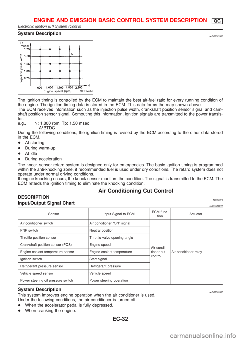
System DescriptionNJEC0015S02
SEF742M
The ignition timing is controlled by the ECM to maintain the best air-fuel ratio for every running condition of
the engine. The ignition timing data is stored in the ECM. This data forms the map shown above.
The ECM receives information such as the injection pulse width, crankshaft position sensor signal and cam-
shaft position sensor signal. Computing this information, ignition signals are transmitted to the power transis-
tor.
e.g., N: 1,800 rpm, Tp: 1.50 msec
AÉBTDC
During the following conditions, the ignition timing is revised by the ECM according to the other data stored
in the ECM.
+At starting
+During warm-up
+At idle
+During acceleration
The knock sensor retard system is designed only for emergencies. The basic ignition timing is programmed
within the anti-knocking zone, if recommended fuel is used under dry conditions. The retard system does not
operate under normal driving conditions.
If engine knocking occurs, the knock sensor monitors the condition. The signal is transmitted to the ECM. The
ECM retards the ignition timing to eliminate the knocking condition.
Air Conditioning Cut Control
DESCRIPTIONNJEC0016Input/Output Signal ChartNJEC0016S01
Sensor Input Signal to ECMECM func-
tionActuator
Air conditioner switch Air conditioner ªONº signal
Air condi-
tioner cut
controlAir conditioner relay PNP switch Neutral position
Throttle position sensor Throttle valve opening angle
Crankshaft position sensor (POS) Engine speed
Engine coolant temperature sensor Engine coolant temperature
Ignition switch Start signal
Refrigerant pressure sensor Refrigerant pressure
Vehicle speed sensor Vehicle speed
Power steering oil pressure switch Power steering operation
System DescriptionNJEC0016S02This system improves engine operation when the air conditioner is used.
Under the following conditions, the air conditioner is turned off.
+When the accelerator pedal is fully depressed.
+When cranking the engine.
ENGINE AND EMISSION BASIC CONTROL SYSTEM DESCRIPTIONQG
Electronic Ignition (EI) System (Cont'd)
EC-32
Page 339 of 2493

h)Fuel pressure
i)Engine compression
j)EGR valve operation
k)Throttle valve
l)EVAP system
+On models equipped with air conditioner, checks should
be carried out while the air conditioner is ªOFFº.
+When checking idle speed on models equipped with A/T,
ignition timing and mixture ratio, checks should be carried
out while shift lever is in ªPº or ªNº position.
+When measuring ªCOº percentage, insert probe more
than 40 cm (15.7 in) into tail pipe.
+Turn off headlamps, heater blower, rear window defogger.
+On vehicles equipped with daytime light systems, set
lighting switch to the 1st position to light only small
lamps.
+Keep front wheels pointed straight ahead.
+If engine stops immediately after starting or idle condition
is unstable, perform the following to initialize IACV-AAC
valve:
a)Stop engine and wait 9 seconds.
b)Turn ignition ªONº and wait 1 second.
c)Turn ignition ªOFFº and wait 9 seconds.
+Make sure the cooling fan has stopped.
BASIC SERVICE PROCEDUREQG
Preparation (Cont'd)
EC-43
Page 371 of 2493

Diagnostic Test Mode I Ð Bulb CheckNJEC0032S03In this mode, the MI on the instrument panel should stay ON. If it remains OFF, check the MI bulb. Refer to
EL-107, ªWARNING LAMPSº or see EC-488.
Diagnostic Test Mode I Ð Malfunction WarningNJEC0032S04
MI Condition
ON When the malfunction is detected or the ECM's CPU is malfunctioning.
OFF No malfunction.
+These DTC numbers are clarified in Diagnostic Test Mode II (SELF-DIAGNOSTIC RESULTS).
Diagnostic Test Mode II Ð Self-diagnostic Results (If so equipped)NJEC0032S05In this mode, the DTC and 1st trip DTC are indicated by the number of blinks of the MI as shown below.
The DTC and 1st trip DTC are displayed at the same time. If the MI does not illuminate in diagnostic test mode
I (Malfunction warning), all displayed items are 1st trip DTCs. If only one code is displayed when the MI illu-
minates in diagnostic test mode II (SELF-DIAGNOSTIC RESULTS), it is a DTC; if two or more codes are
displayed, they may be either DTCs or 1st trip DTCs. DTC No. is same as that of 1st trip DTC. These uni-
dentified codes can be identified by using the CONSULT-II or GST. A DTC will be used as an example for how
to read a code.
SEF952W
A particular trouble code can be identified by the number of four-digit numeral flashes. The ªzeroº is indicated
by the number of ten flashes. The length of time the 1000th-digit numeral flashes on and off is 1.2 seconds
consisting of an ON (0.6-second)-OFF (0.6-second) cycle.
The 100th-digit numeral and lower digit numerals consist of a 0.3-second ON and 0.3-second OFF cycle.
A change from one digit numeral to another occurs at an interval of 1.0 second OFF. In other words, the lat-
ter numeral appears on the display 1.3 seconds after the former numeral has disappeared.
A change from one trouble code to another occurs at an interval of 1.8 second off.
In this way, all the detected malfunctions are classified by their DTC numbers. The DTC ª0000º refers to no
malfunction. (See TROUBLE DIAGNOSIS Ð INDEX, EC-10.)
How to Erase Diagnostic Test Mode II (Self-diagnostic results)
NJEC0032S0501The DTC can be erased from the backup memory in the ECM when the diagnostic test mode is changed from
Diagnostic Test Mode II to Diagnostic Test Mode I. (Refer to ªHow To Switch Diagnostic Test Modesº, EC-74.)
+If the battery is disconnected, the DTC will be lost from the backup memory after approx. 24 hours.
+Be careful not to erase the stored memory before starting trouble diagnoses.
Diagnostic Test Mode II Ð Heated Oxygen Sensor 1 Monitor (Front) (If so equipped)NJEC0032S06In this mode, the MI displays the condition of the fuel mixture (lean or rich) which is monitored by the heated
oxygen sensor 1 (front).
ON BOARD DIAGNOSTIC SYSTEM DESCRIPTIONQG
Malfunction Indicator (MI) (Cont'd)
EC-75
Page 382 of 2493
![NISSAN ALMERA N16 2001 Electronic Repair Manual Monitored item [Unit]ECM
input
signalsMain
signalsDescription Remarks
HO2S2 MNTR (B1)
[RICH/LEAN]j+Display of heated oxygen sensor 2 (rear)
signal:
RICH ... means the amount of oxygen after
three way NISSAN ALMERA N16 2001 Electronic Repair Manual Monitored item [Unit]ECM
input
signalsMain
signalsDescription Remarks
HO2S2 MNTR (B1)
[RICH/LEAN]j+Display of heated oxygen sensor 2 (rear)
signal:
RICH ... means the amount of oxygen after
three way](/manual-img/5/57351/w960_57351-381.png)
Monitored item [Unit]ECM
input
signalsMain
signalsDescription Remarks
HO2S2 MNTR (B1)
[RICH/LEAN]j+Display of heated oxygen sensor 2 (rear)
signal:
RICH ... means the amount of oxygen after
three way catalyst is relatively small.
LEAN ... means the amount of oxygen after
three way catalyst is relatively large.+When the engine is stopped, a cer-
tain value is indicated.
VHCL SPEED SE
[km/h] or [mph]jj+The vehicle speed computed from the
vehicle speed sensor signal is displayed.
BATTERY VOLT [V]j+The power supply voltage of ECM is dis-
played.
THRTL POS SEN [V]jj+The throttle position sensor signal voltage is
displayed.
FUEL T/TMP SE
[ÉC] or [ÉF]*+The fuel temperature judged from the fuel
tank temperature sensor signal voltage is
displayed.
INT/A TEMP SE
[ÉC] or [ÉF]j+The intake air temperature determined by
the signal voltage of the intake air tempera-
ture sensor is indicated.
EGR TEMP SEN [V]*jj+The signal voltage of the EGR temperature
sensor is displayed.
START SIGNAL
[ON/OFF]jj+Indicates [ON/OFF] condition from the
starter signal.+After starting the engine, [OFF] is
displayed regardless of the starter
signal.
CLSD THL POS
[ON/OFF]jj+Indicates idle position [ON/OFF] computed
by ECM according to the throttle position
sensor signal.
CLSD THL/P SW
[ON/OFF]*j+Indicates mechanical contact [ON/OFF]
condition of the closed throttle position
switch.
AIR COND SIG
[ON/OFF]jj+Indicates [ON/OFF] condition of the air con-
ditioner switch as determined by the air
conditioning signal.
P/N POSI SW
[ON/OFF]jj+Indicates [ON/OFF] condition from the PNP
switch signal.
PW/ST SIGNAL
[ON/OFF]jj+Indicates [ON/OFF] condition of the power
steering oil pressure switch determined by
the power steering oil pressure switch sig-
nal.
LOAD SIGNAL
[ON/OFF]jj+Indicates [ON/OFF] condition from the elec-
trical load signal and/or lighting switch.
ON ... rear defogger is operating and/or
lighting switch is on.
OFF ... rear defogger is not operating and
lighting switch is not on.
IGNITION SW
[ON/OFF]j+Indicates [ON/OFF] condition from ignition
switch.
HEATER FAN SW
[ON/OFF]j+Indicates [ON/OFF] condition from the
heater fan switch.
INJ PULSE-B1
[msec]j+Indicates the actual fuel injection pulse
width compensated by ECM according to
the input signals.+When the engine is stopped, a cer-
tain computed value is indicated.
ON BOARD DIAGNOSTIC SYSTEM DESCRIPTIONQG
CONSULT-II (Cont'd)
EC-86
Page 558 of 2493
On Board Diagnosis LogicNJEC0202If a misfire occurs, the engine speed will fluctuate. If the fluctuation is detected by the crankshaft position sen-
sor (POS), the misfire is diagnosed.
Sensor Input Signal to ECM ECM function
Crankshaft position sensor (POS) Engine speed On board diagnosis of misfire
The misfire detection logic consists of the following two conditions.
1. One Trip Detection Logic (Three Way Catalyst Damage)
When a misfire is detected which will overheat and damage the three way catalyst, the MI will start blink-
ing; even during the first trip. In this condition, ECM monitors the misfire every 200 revolutions.
If the misfire frequency decreases to a level that will not damage the three way catalyst, the MI will change
from blinking to lighting up. (After the first trip detection, the MI will light up from engine starting. If a mis-
fire is detected that will cause three way catalyst damage, the MI will start blinking.)
2. Two Trip Detection Logic (Exhaust quality deterioration)
When a misfire that will not damage the three way catalyst (but will affect exhaust emission) occurs, the
MI will light up based on two trip detection logic. In this condition, ECM monitors the misfire for every 1,000
revolutions of the engine.
DTC No. Malfunction is detected when ... Check Items (Possible Cause)
P0300
0300+Multiple cylinders misfire.+Improper spark plug
+Insufficient compression
+Incorrect fuel pressure
+EGR volume control valve
+The injector circuit is open or shorted
+Injectors
+Intake air leak
+Insufficient ignition spark
+Lack of fuel
+Heated oxygen sensor 1 (front) P0301
0301+No. 1 cylinder misfires.
P0302
0302+No. 2 cylinder misfires.
P0303
0303+No. 3 cylinder misfires.
P0304
0304+No. 4 cylinder misfires.
SEF058Y
DTC Confirmation ProcedureNJEC0203CAUTION:
Always drive vehicle at a safe speed.
NOTE:
If ªDTC Confirmation Procedureº has been previously conducted,
always turn ignition switch ªOFFº and wait at least 9 seconds
before conducting the next test.
With CONSULT-II
1) Turn ignition switch ªONº, and select ªDATA MONITORº mode
with CONSULT-II.
2) Start engine and warm it up to normal operating temperature.
3) Turn ignition switch ªOFFº and wait at least 9 seconds.
4) Start engine again and drive at 1,500 - 3,000 rpm for at least
3 minutes.
Hold the accelerator pedal as steady as possible.
NOTE:
Refer to the freeze frame data for the test driving conditions.
5) If 1st trip DTC is detected, go to ªDiagnostic Procedureº,
EC-263.
With GST
Follow the procedure ªWith CONSULT-IIº above.
DTC P0300 - P0304 NO.4-1CYLINDER MISFIRE, MULTIPLE CYLINDER
MISFIRE
QG
On Board Diagnosis Logic
EC-262
Page 569 of 2493
On Board Diagnosis LogicNJEC0553
DTC No. Malfunction is detected when ... Check Items (Possible Cause)
P0335
0802+The 10É signal is not entered to ECM for the first few
seconds during engine cranking.
+The 10É signal is not entered to ECM during engine run-
ning.
+The 10É signal is not in the normal pattern at each
engine revolution.+Harness or connectors
(The crankshaft position sensor (POS) circuit is
open or shorted.)
+Crankshaft position sensor (POS)
+Starter motor (Refer to EL section.)
+Starting system circuit (Refer to EL section.)
+Dead (Weak) battery
SEF058Y
DTC Confirmation ProcedureNJEC0554NOTE:
If ªDTC Confirmation Procedureº has been previously conducted,
always turn ignition switch ªOFFº and wait at least 9 seconds
before conducting the next test.
With CONSULT-II
1) Turn ignition switch ªONº and select ªDATA MONITORº mode
with CONSULT-II.
2) Start engine and run it for at least 2 seconds at idle speed.
3) If 1st trip DTC is detected, go to ªDiagnostic Procedureº,
EC-275.
With GST
Follow the procedure ªWith CONSULT-IIº above.
DTC P0335 CRANKSHAFT POSITION SENSOR (POS)QG
On Board Diagnosis Logic
EC-273
Page 575 of 2493
On Board Diagnosis LogicNJEC0222
DTC No. Malfunction is detected when ... Check Items (Possible Cause)
P0340
0340+The cylinder No. signal is not entered to ECM for the first
few seconds during engine cranking.
+The cylinder No. signal is not entered to ECM during
engine running.
+The cylinder No. signal is not in the normal pattern dur-
ing engine running.+Harness or connectors
(The camshaft position sensor (PHASE) circuit is
open or shorted.)
+Camshaft position sensor (PHASE)
+Starter motor (Refer to EL section.)
+Starting system circuit (Refer to EL section.)
DTC Confirmation ProcedureNJEC0223NOTE:
If ªDTC Confirmation Procedureº has been previously conducted,
always turn ignition switch ªOFFº and wait at least 9 seconds
before conducting the next test.
TESTING CONDITION:
Before performing the following procedure, confirm that bat-
tery voltage is more than 10.5V.
SEF013Y
With CONSULT-II
1) Turn ignition switch ªONº.
2) Select ªDATA MONITORº mode with CONSULT-II.
3) Crank engine for at least 2 seconds.
4) If 1st trip DTC is detected, go to ªDiagnostic Procedureº,
EC-281.
With GST
Follow the procedure ªWith CONSULT-IIº above.
DTC P0340 CAMSHAFT POSITION SENSOR (CMPS) (PHASE)QG
On Board Diagnosis Logic
EC-279
Page 577 of 2493
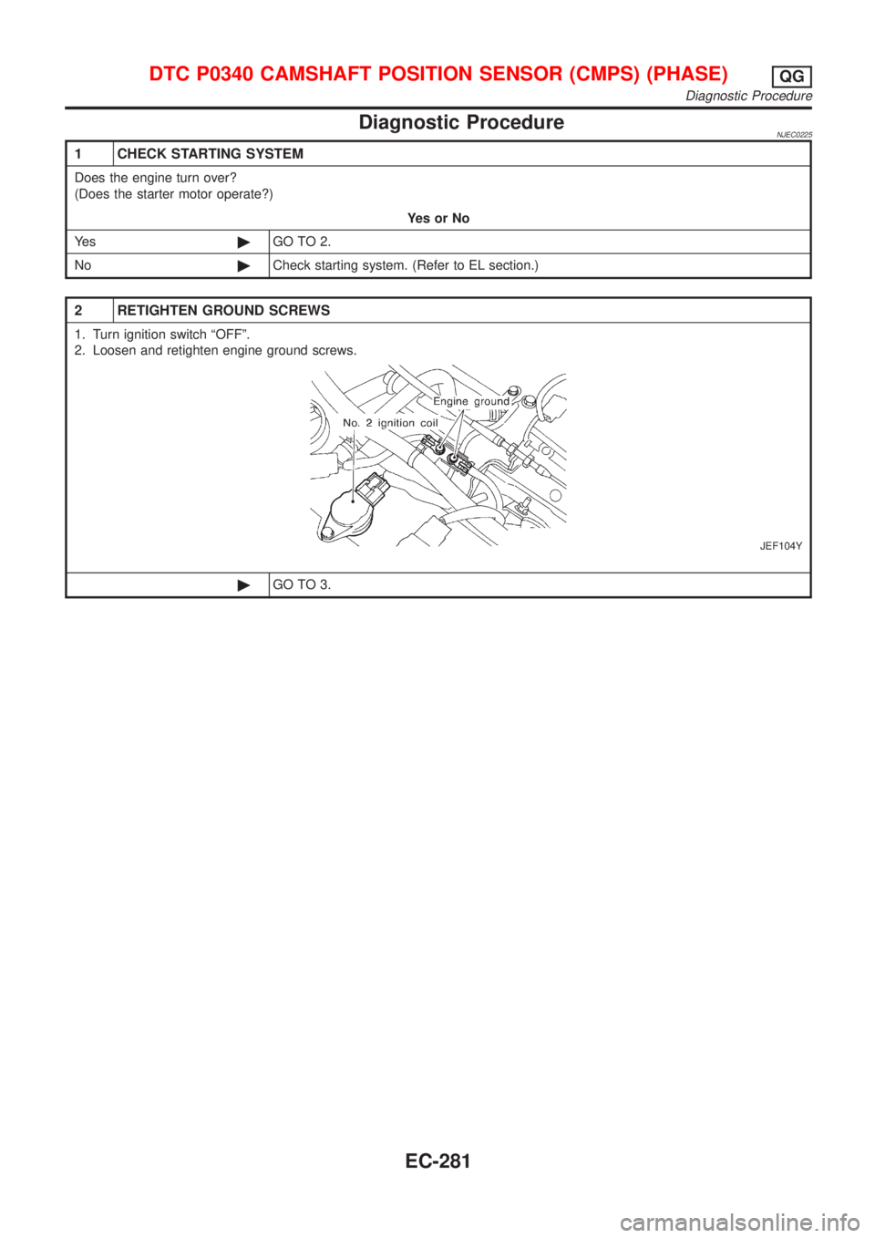
Diagnostic ProcedureNJEC0225
1 CHECK STARTING SYSTEM
Does the engine turn over?
(Does the starter motor operate?)
YesorNo
Ye s©GO TO 2.
No©Check starting system. (Refer to EL section.)
2 RETIGHTEN GROUND SCREWS
1. Turn ignition switch ªOFFº.
2. Loosen and retighten engine ground screws.
JEF104Y
©GO TO 3.
DTC P0340 CAMSHAFT POSITION SENSOR (CMPS) (PHASE)QG
Diagnostic Procedure
EC-281