2001 NISSAN ALMERA N16 Starting
[x] Cancel search: StartingPage 806 of 2493
JEF341Y
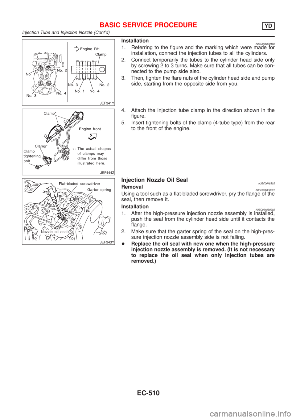
InstallationNJEC0618S01021. Referring to the figure and the marking which were made for
installation, connect the injection tubes to all the cylinders.
2. Connect temporarily the tubes to the cylinder head side only
by screwing 2 to 3 turns. Make sure that all tubes can be con-
nected to the pump side also.
3. Then, tighten the flare nuts of the cylinder head side and pump
side, starting from the opposite side from you.
JEF444Z
4. Attach the injection tube clamp in the direction shown in the
figure.
5. Insert tightening bolts of the clamp (4-tube type) from the rear
to the front of the engine.
JEF343Y
Injection Nozzle Oil SealNJEC0618S02RemovalNJEC0618S0201Using a tool such as a flat-bladed screwdriver, pry the flange of the
seal, then remove it.
Installation
NJEC0618S02021. After the high-pressure injection nozzle assembly is installed,
push the seal from the cylinder head side until it contacts the
flange.
2. Make sure that the garter spring of the seal on the high-pres-
sure injection nozzle assembly side is not falling.
+Replace the oil seal with new one when the high-pressure
injection nozzle assembly is removed. (It is not necessary
to replace the oil seal when only injection tubes are
removed.)
BASIC SERVICE PROCEDUREYD
Injection Tube and Injection Nozzle (Cont'd)
EC-510
Page 819 of 2493
+Erasing the emission-related diagnostic information using CONSULT-II is easier and quicker than
switching the diagnostic test mode using the data link connector.
Malfunction Indicator (MI)
DESCRIPTIONNJEC0628
SAT652J
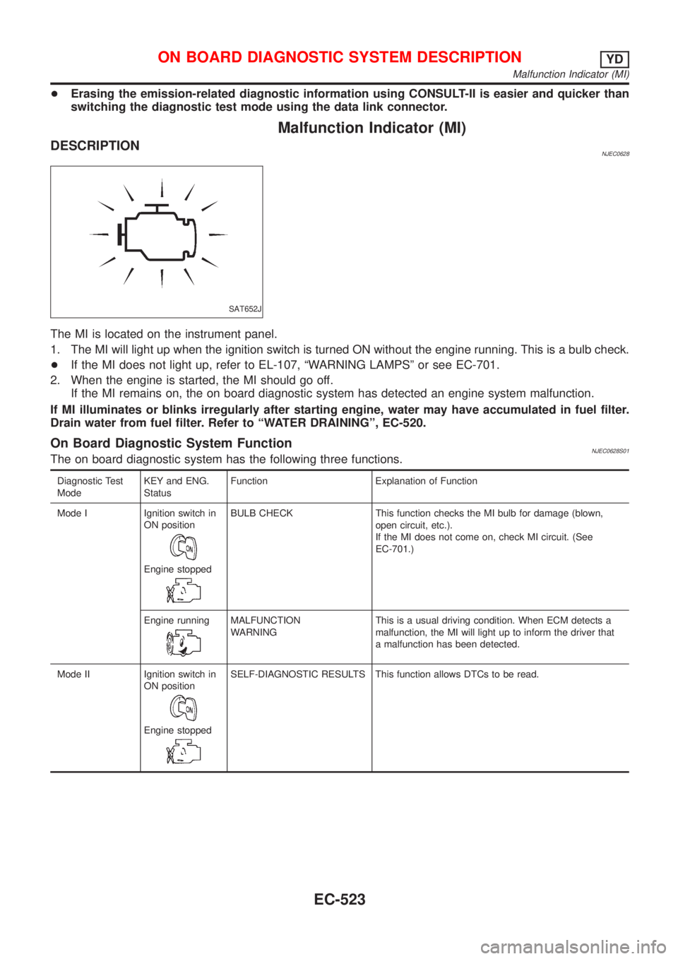
The MI is located on the instrument panel.
1. The MI will light up when the ignition switch is turned ON without the engine running. This is a bulb check.
+If the MI does not light up, refer to EL-107, ªWARNING LAMPSº or see EC-701.
2. When the engine is started, the MI should go off.
If the MI remains on, the on board diagnostic system has detected an engine system malfunction.
If MI illuminates or blinks irregularly after starting engine, water may have accumulated in fuel filter.
Drain water from fuel filter. Refer to ªWATER DRAININGº, EC-520.
On Board Diagnostic System FunctionNJEC0628S01The on board diagnostic system has the following three functions.
Diagnostic Test
ModeKEY and ENG.
StatusFunction Explanation of Function
Mode I Ignition switch in
ON position
Engine stopped
BULB CHECK This function checks the MI bulb for damage (blown,
open circuit, etc.).
If the MI does not come on, check MI circuit. (See
EC-701.)
Engine running
MALFUNCTION
WARNINGThis is a usual driving condition. When ECM detects a
malfunction, the MI will light up to inform the driver that
a malfunction has been detected.
Mode II Ignition switch in
ON position
Engine stopped
SELF-DIAGNOSTIC RESULTS This function allows DTCs to be read.
ON BOARD DIAGNOSTIC SYSTEM DESCRIPTIONYD
Malfunction Indicator (MI)
EC-523
Page 821 of 2493
Diagnostic Test Mode I Ð Bulb CheckNJEC0628S03In this mode, the MI on the instrument panel should stay ON. If it remains OFF, check the bulb. Refer to EL-107,
ªWARNING LAMPSº or see EC-701.
Diagnostic Test Mode I Ð Malfunction WarningNJEC0628S04
MI Condition
ON When the malfunction is detected or the ECM's CPU is malfunctioning.
OFF No malfunction.
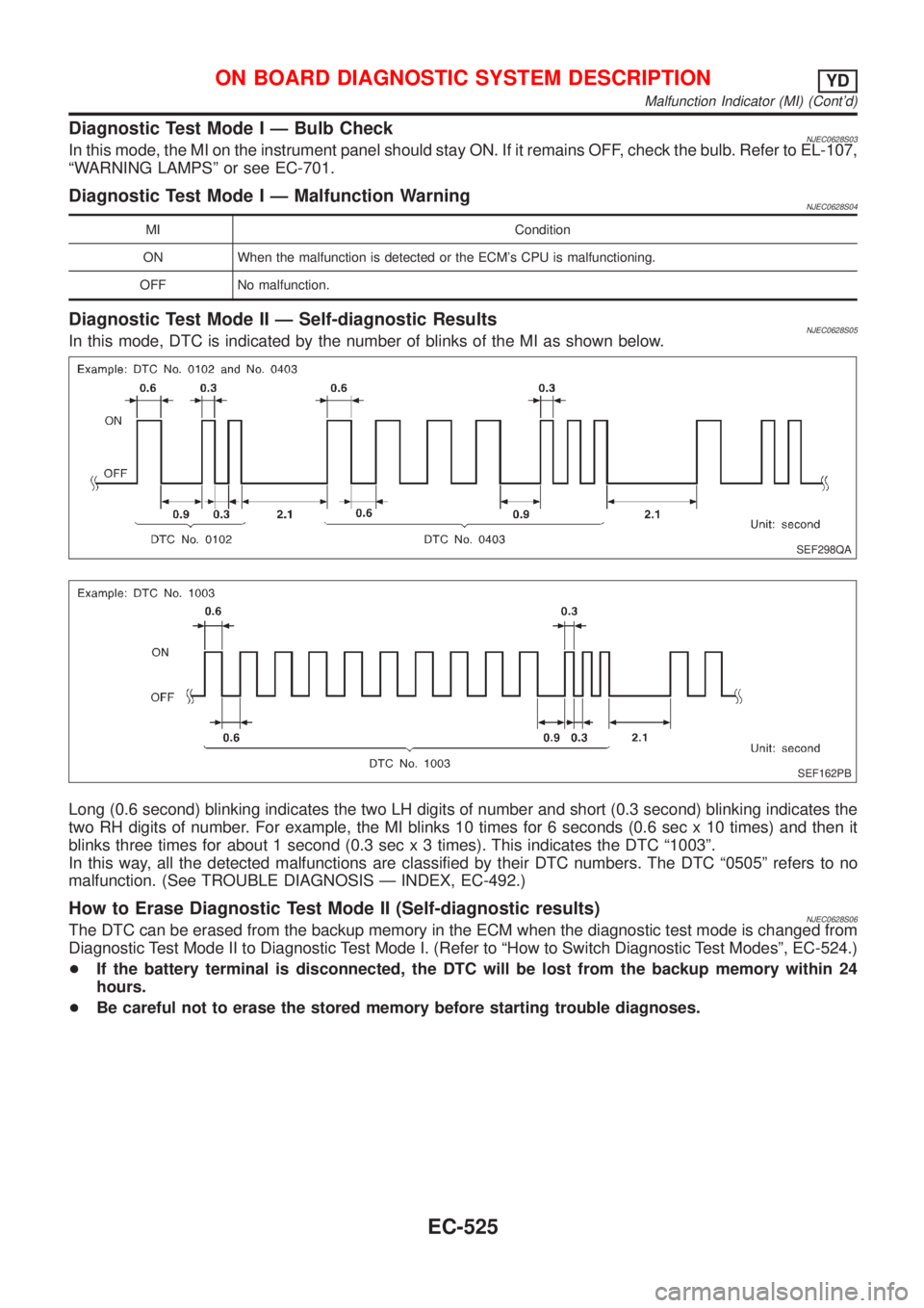
Diagnostic Test Mode II Ð Self-diagnostic ResultsNJEC0628S05In this mode, DTC is indicated by the number of blinks of the MI as shown below.
SEF298QA
SEF162PB
Long (0.6 second) blinking indicates the two LH digits of number and short (0.3 second) blinking indicates the
two RH digits of number. For example, the MI blinks 10 times for 6 seconds (0.6 sec x 10 times) and then it
blinks three times for about 1 second (0.3 sec x 3 times). This indicates the DTC ª1003º.
In this way, all the detected malfunctions are classified by their DTC numbers. The DTC ª0505º refers to no
malfunction. (See TROUBLE DIAGNOSIS Ð INDEX, EC-492.)
How to Erase Diagnostic Test Mode II (Self-diagnostic results)NJEC0628S06The DTC can be erased from the backup memory in the ECM when the diagnostic test mode is changed from
Diagnostic Test Mode II to Diagnostic Test Mode I. (Refer to ªHow to Switch Diagnostic Test Modesº, EC-524.)
+If the battery terminal is disconnected, the DTC will be lost from the backup memory within 24
hours.
+Be careful not to erase the stored memory before starting trouble diagnoses.
ON BOARD DIAGNOSTIC SYSTEM DESCRIPTIONYD
Malfunction Indicator (MI) (Cont'd)
EC-525
Page 825 of 2493
![NISSAN ALMERA N16 2001 Electronic Repair Manual Monitored item
[Unit]ECM
input
signalsMain
signalsDescription Remarks
SPILL/V [ÉCA]
j+The control position of spill valve (sent
from electronic control fuel injection
pump) is displayed.
BATTERY VOLT NISSAN ALMERA N16 2001 Electronic Repair Manual Monitored item
[Unit]ECM
input
signalsMain
signalsDescription Remarks
SPILL/V [ÉCA]
j+The control position of spill valve (sent
from electronic control fuel injection
pump) is displayed.
BATTERY VOLT](/manual-img/5/57351/w960_57351-824.png)
Monitored item
[Unit]ECM
input
signalsMain
signalsDescription Remarks
SPILL/V [ÉCA]
j+The control position of spill valve (sent
from electronic control fuel injection
pump) is displayed.
BATTERY VOLT [V]
jj+The power supply voltage of ECM is
displayed.
P/N POSI SW*1
[ON/OFF] (where
fitted)jj+Indicates [ON/OFF] condition from the
park/neutral position switch signal.
START SIGNAL
[ON/OFF]jj+Indicates [ON/OFF] condition from the
starter signal.+After starting the engine, [OFF] is dis-
played regardless of the starter signal.
BRAKE SW
[ON/OFF]jj+Indicates [ON/OFF] condition from the
stop lamp switch signal.
BRAKE SW2
[ON/OFF]jj+Indicates [ON/OFF] condition from the
brake pedal position switch signal.
IGN SW
[ON/OFF]jj+Indicates [ON/OFF] condition from igni-
tion switch signal.
MAS AIR/FL SE [V]
jj+The signal voltage of the mass air flow
sensor is displayed.+When the engine is stopped, a certain
value is indicated.
INT/A VOLUME [mg/]+The intake air volume computed from
the mass air flow sensor signal is dis-
played.
F/CUT SIGNAL
[ON/OFF]
j+The [ON/OFF] condition from decelera-
tion fuel cut signal (sent from electronic
control fuel injection pump) is displayed.
OFF´´´Fuel is cut off.
ON´´´Fuel is not cut off.
GLOW RLY
[ON/OFF]j+The glow relay control condition (deter-
mined by ECM according to the input
signal) is displayed.
COOLING FAN
[LOW/HI/OFF]
j+Indicates the control condition of the
cooling fans (determined by ECM
according to the input signal).
+LOW ... Operates at low speed.
HI ... Operates at high speed.
OFF ... Stopped.
BARO SEN [kPa]
jj+The barometric pressure (determined
by the signal voltage from the baromet-
ric pressure sensor built into the ECM)
is displayed.
EGR VOL CON/V
[step]
j+Indicates the EGR volume control value
computed by the ECM according to the
input signals.
+The opening becomes larger as the
value increases.
*1: On models not equipped with park/neutral position (PNP) switch, ªOFFº is always displayed regardless of gear shift position.
NOTE:
Any monitored item that does not match the vehicle being diagnosed is deleted from the display automatically.
ON BOARD DIAGNOSTIC SYSTEM DESCRIPTIONYD
CONSULT-II (Cont'd)
EC-529
Page 968 of 2493

On Board Diagnosis LogicNJEC1258The ECM checks if battery voltage is within the tolerance range for the engine control system.
DTC Malfunction is detected when ... Check Items (Possible Cause)
P1660
0502+An abnormally high or low voltage from the battery
is sent to ECM.+Incorrect jump starting
+Battery
+Alternator
+ECM
DTC Confirmation ProcedureNJEC1259With CONSULT-II
1) Check the following.
+Jumper cables are connected for jump starting.
+Battery or alternator has been replaced.
If the result is ªYesº for one item or more, skip the following steps and go to ªDiagnostic Procedureº,
EC-672.
2) Check that the positive battery terminal is connected to battery properly. If NG, reconnect it properly.
3) Check that the alternator functions properly. Refer to SC-26, ªTrouble Diagnosisº.
4) Turn ignition switch ªONº and select ªDATA MONITORº mode with CONSULT-II.
5) Wait one minute.
6) If DTC is detected, go to ªDiagnostic Procedureº, EC-672.
If DTC is not detected, go to next step.
7) Start engine and wait one minute at idle.
8) If DTC is detected, go to ªDiagnostic Procedureº, EC-672.
Without CONSULT-II
1) Check the following.
+Jumper cables are connected for jump starting.
+Battery or alternator has been replaced.
If the result is ªYesº for one item or more, skip the following steps and go to ªDiagnostic Procedureº,
EC-672.
2) Check that the positive battery terminal is connected to battery properly. If NG, reconnect it properly.
3) Check that the alternator functions properly. Refer to SC-26, ªTrouble Diagnosisº.
4) Turn ignition switch ªONº and wait one minute.
5) Turn ignition switch ªOFFº, wait 5 seconds and then turn ªONº.
6) Perform ªDiagnostic Test Mode II (Self-diagnostic result)º with ECM.
7) If DTC is detected, go to ªDiagnostic Procedureº, EC-672.
If DTC is not detected, go to next step.
8) Start engine and wait one minute at idle.
9) Turn ignition switch ªOFFº, wait 5 seconds and then turn ªONº.
10) Perform ªDiagnostic Test Mode II (Self-diagnostic result)º with ECM.
11) If DTC is detected, go to ªDiagnostic Procedureº, EC-672.
Diagnostic ProcedureNJEC1260
1 INSPECTION START
Are jumper cables connected for the jump starting?
YesorNo
Ye s©GO TO 3.
No©GO TO 2.
DTC P1660 BATTERY VOLTAGEYD
On Board Diagnosis Logic
EC-672
Page 973 of 2493
DescriptionNJEC0760SYSTEM DESCRIPTIONNJEC0760S01
Sensor Input Signal to ECMECM
Func-
tionActuator
Crankshaft position sensor
(TDC)Engine speed
Glow
controlGlow lamp,
Glow relay
¯
Glow plugs Engine coolant tempera-
ture sensorEngine coolant tem-
perature
When engine coolant temperature is more than approximately
75ÉC (167ÉF), the glow relay turns off.
When coolant temperature is lower than approximately 75ÉC
(167ÉF):
+Ignition switch ON
After ignition switch has turned to ON, the glow relay turns ON
for a certain period of time in relation to engine coolant
temperature, allowing current to flow through glow plug.
+Cranking
The glow relay turns ON, allowing current to flow through glow
plug.
+Starting
After engine has started, current continues to flow through
glow plug (after-glow mode) for a certain period in relation to
engine coolant temperature.
The glow indicator lamp turns ON for a certain period of time in
relation to engine cooalnt temperature at the time glow relay is
turned ON.
SEF376Y
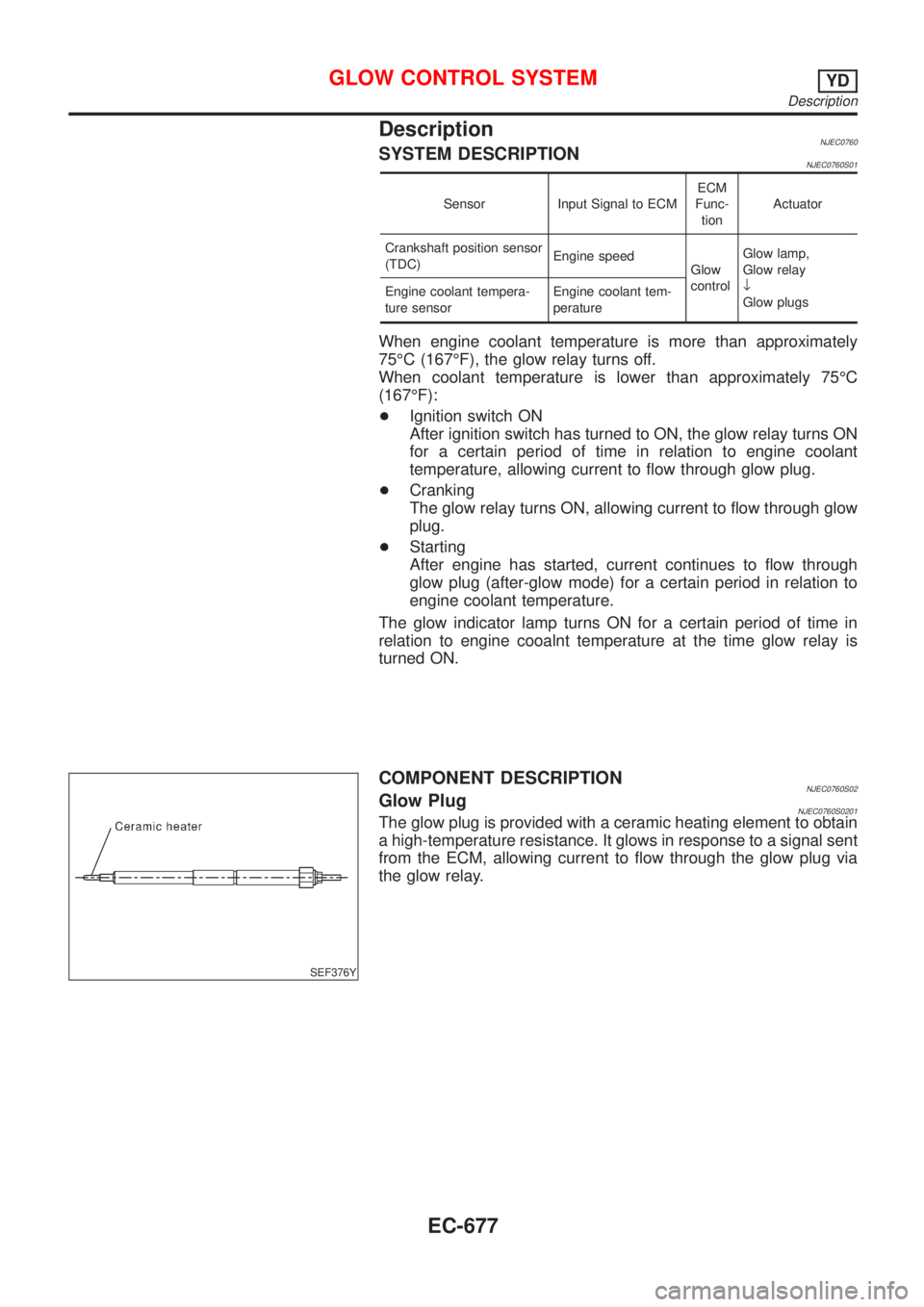
COMPONENT DESCRIPTIONNJEC0760S02Glow PlugNJEC0760S0201The glow plug is provided with a ceramic heating element to obtain
a high-temperature resistance. It glows in response to a signal sent
from the ECM, allowing current to flow through the glow plug via
the glow relay.
GLOW CONTROL SYSTEMYD
Description
EC-677
Page 982 of 2493

DescriptionNJEC0764SYSTEM DESCRIPTIONNJEC0764S01
Sensor Input Signal to ECM ECM Function Actuator
Electronic controlled fuel injection pump Fuel injection signal
EGR volume con-
trolEGR volume control
valve Crankshaft position sensor (TDC) Engine speed
Vehicle speed sensor Vehicle speed
Engine coolant temperature sensor Engine coolant temperature
Ignition switch Start signal
Accelerator position sensor Accelerator position
Mass air flow sensor Amount of intake air
Air conditioner switch Air conditioner operation
Electrical load Electrical load signal
This system controls flow rate of EGR led from exhaust manifold
to intake manifold. The opening of the EGR by-pass passage in the
EGR volume control valve changes to control the flow rate. A
built-in step motor moves the valve in steps corresponding to the
ECM output pulses. The opening of the valve varies for optimum
engine control. The optimum value stored in the ECM is determined
by considering various engine conditions.
The EGR volume control valve remains close under the following
conditions.
+Engine stopped
+Engine starting
+Low engine coolant temperature
+Excessively high engine coolant temperature
+High engine speed
+Wide open throttle
SEF908Y
SEF411Y
COMPONENT DESCRIPTIONNJEC0764S02EGR Volume Control ValveNJEC0764S0201The EGR volume control valve uses a step motor to control the flow
rate of EGR from exhaust manifold. This motor has four winding
phases. It operates according to the output pulse signal of the
ECM. Two windings are turned ON and OFF in sequence. Each
time an ON pulse is issued, the valve opens or closes, changing
the flow rate. When no change in the flow rate is needed, the ECM
does not issue the pulse signal. A certain voltage signal is issued
so that the valve remains at that particular opening.
EGR VOLUME CONTROL SYSTEMYD
Description
EC-686
Page 1279 of 2493
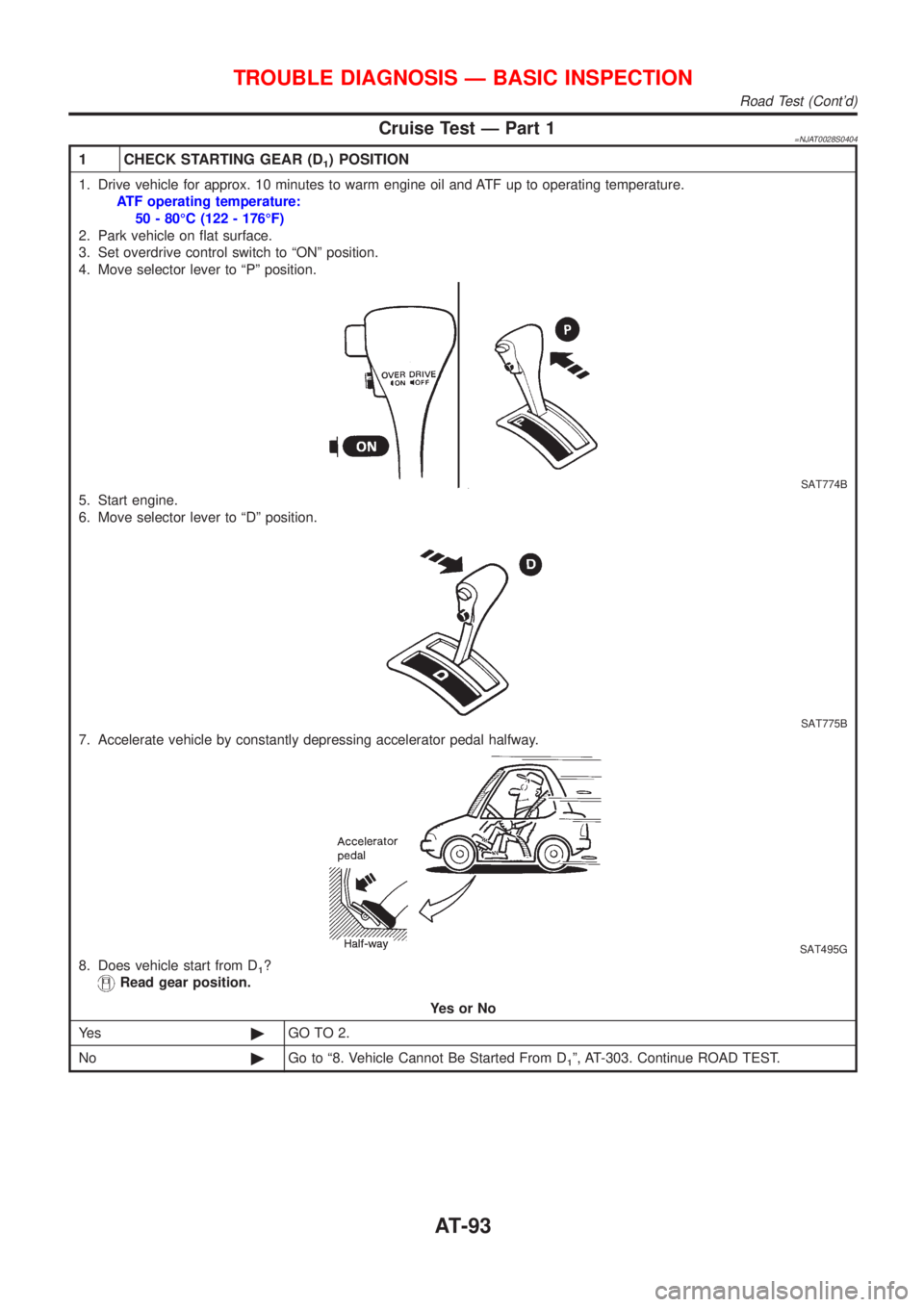
Cruise Test Ð Part 1=NJAT0028S0404
1 CHECK STARTING GEAR (D1) POSITION
1. Drive vehicle for approx. 10 minutes to warm engine oil and ATF up to operating temperature.
ATF operating temperature:
50 - 80ÉC (122 - 176ÉF)
2. Park vehicle on flat surface.
3. Set overdrive control switch to ªONº position.
4. Move selector lever to ªPº position.
SAT774B
5. Start engine.
6. Move selector lever to ªDº position.
SAT775B
7. Accelerate vehicle by constantly depressing accelerator pedal halfway.
SAT495G
8. Does vehicle start from D1?
Read gear position.
YesorNo
Ye s©GO TO 2.
No©Go to ª8. Vehicle Cannot Be Started From D
1º, AT-303. Continue ROAD TEST.
TROUBLE DIAGNOSIS Ð BASIC INSPECTION
Road Test (Cont'd)
AT-93