2001 NISSAN ALMERA N16 Starting
[x] Cancel search: StartingPage 2319 of 2493
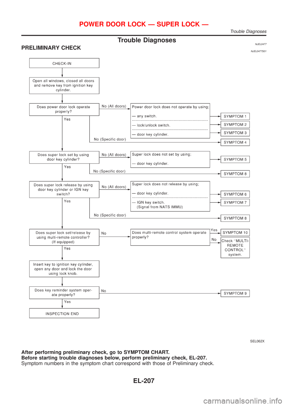
Trouble DiagnosesNJEL0477PRELIMINARY CHECKNJEL0477S01
SEL062X
After performing preliminary check, go to SYMPTOM CHART.
Before starting trouble diagnoses below, perform preliminary check, EL-207.
Symptom numbers in the symptom chart correspond with those of Preliminary check.
POWER DOOR LOCK Ð SUPER LOCK Ð
Trouble Diagnoses
EL-207
Page 2352 of 2493
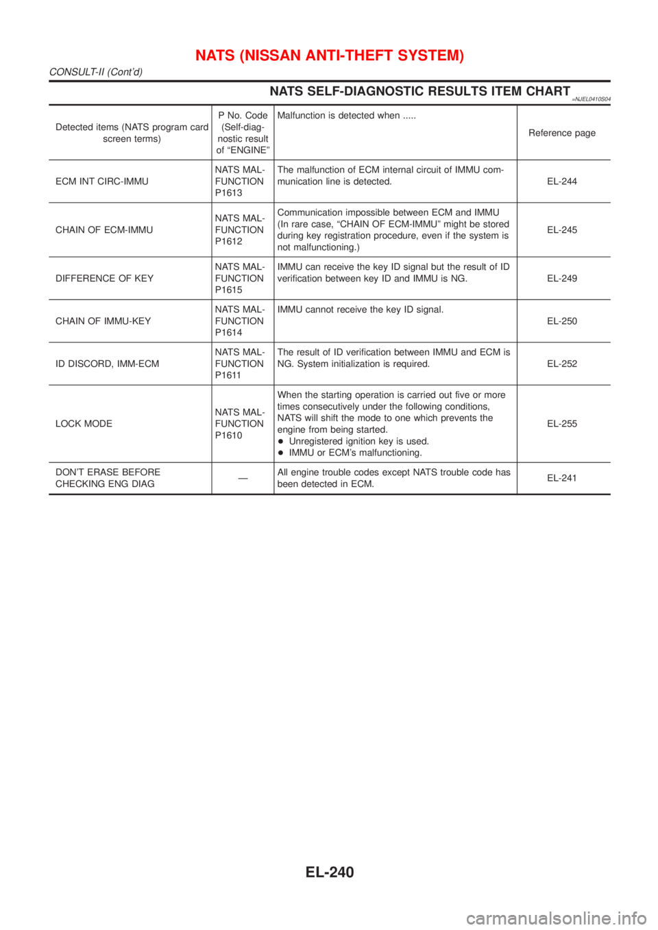
NATS SELF-DIAGNOSTIC RESULTS ITEM CHART=NJEL0410S04
Detected items (NATS program card
screen terms)P No. Code
(Self-diag-
nostic result
of ªENGINEºMalfunction is detected when .....
Reference page
ECM INT CIRC-IMMUNATS MAL-
FUNCTION
P1613The malfunction of ECM internal circuit of IMMU com-
munication line is detected. EL-244
CHAIN OF ECM-IMMUNATS MAL-
FUNCTION
P1612Communication impossible between ECM and IMMU
(In rare case, ªCHAIN OF ECM-IMMUº might be stored
during key registration procedure, even if the system is
not malfunctioning.)EL-245
DIFFERENCE OF KEYNATS MAL-
FUNCTION
P1615IMMU can receive the key ID signal but the result of ID
verification between key ID and IMMU is NG. EL-249
CHAIN OF IMMU-KEYNATS MAL-
FUNCTION
P1614IMMU cannot receive the key ID signal.
EL-250
ID DISCORD, IMM-ECMNATS MAL-
FUNCTION
P1611The result of ID verification between IMMU and ECM is
NG. System initialization is required. EL-252
LOCK MODENATS MAL-
FUNCTION
P1610When the starting operation is carried out five or more
times consecutively under the following conditions,
NATS will shift the mode to one which prevents the
engine from being started.
+Unregistered ignition key is used.
+IMMU or ECM's malfunctioning.EL-255
DON'T ERASE BEFORE
CHECKING ENG DIAGÐAll engine trouble codes except NATS trouble code has
been detected in ECM.EL-241
NATS (NISSAN ANTI-THEFT SYSTEM)
CONSULT-II (Cont'd)
EL-240
Page 2424 of 2493
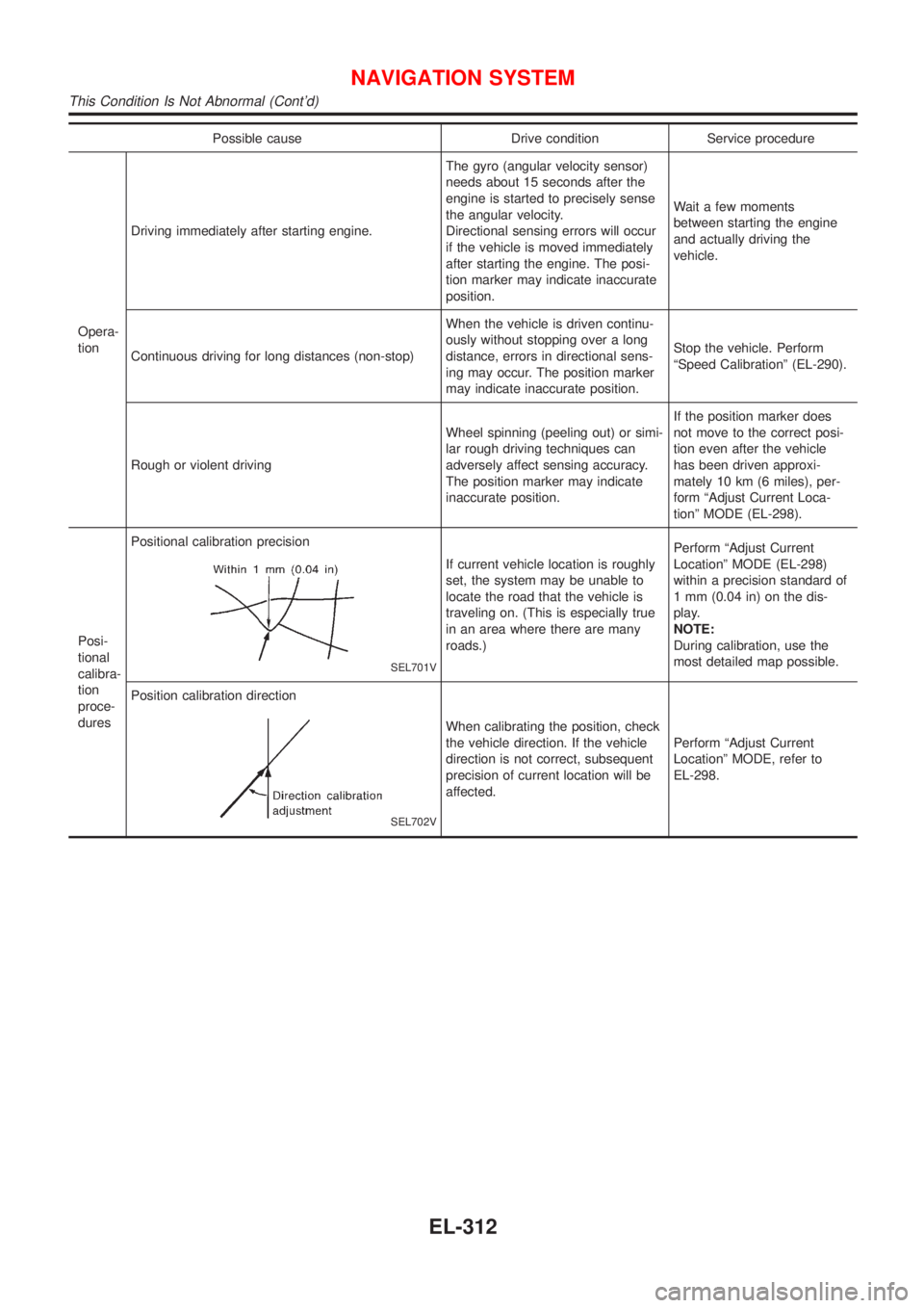
Possible cause Drive condition Service procedure
Opera-
tionDriving immediately after starting engine.The gyro (angular velocity sensor)
needs about 15 seconds after the
engine is started to precisely sense
the angular velocity.
Directional sensing errors will occur
if the vehicle is moved immediately
after starting the engine. The posi-
tion marker may indicate inaccurate
position.Wait a few moments
between starting the engine
and actually driving the
vehicle.
Continuous driving for long distances (non-stop)When the vehicle is driven continu-
ously without stopping over a long
distance, errors in directional sens-
ing may occur. The position marker
may indicate inaccurate position.Stop the vehicle. Perform
ªSpeed Calibrationº (EL-290).
Rough or violent drivingWheel spinning (peeling out) or simi-
lar rough driving techniques can
adversely affect sensing accuracy.
The position marker may indicate
inaccurate position.If the position marker does
not move to the correct posi-
tion even after the vehicle
has been driven approxi-
mately 10 km (6 miles), per-
form ªAdjust Current Loca-
tionº MODE (EL-298).
Posi-
tional
calibra-
tion
proce-
duresPositional calibration precision
SEL701V
If current vehicle location is roughly
set, the system may be unable to
locate the road that the vehicle is
traveling on. (This is especially true
in an area where there are many
roads.)Perform ªAdjust Current
Locationº MODE (EL-298)
within a precision standard of
1 mm (0.04 in) on the dis-
play.
NOTE:
During calibration, use the
most detailed map possible.
Position calibration direction
SEL702V
When calibrating the position, check
the vehicle direction. If the vehicle
direction is not correct, subsequent
precision of current location will be
affected.Perform ªAdjust Current
Locationº MODE, refer to
EL-298.
NAVIGATION SYSTEM
This Condition Is Not Abnormal (Cont'd)
EL-312
Page 2428 of 2493
+The enlarged intersection map may display an ªUnknown streetº message at some street intersections.
+Because of road configuration, etc. the guide may finish early. If this occurs, follow the marker to reach
your destination.
+Destination area side information (left side and right side) may differ from actual conditions because of
data error.
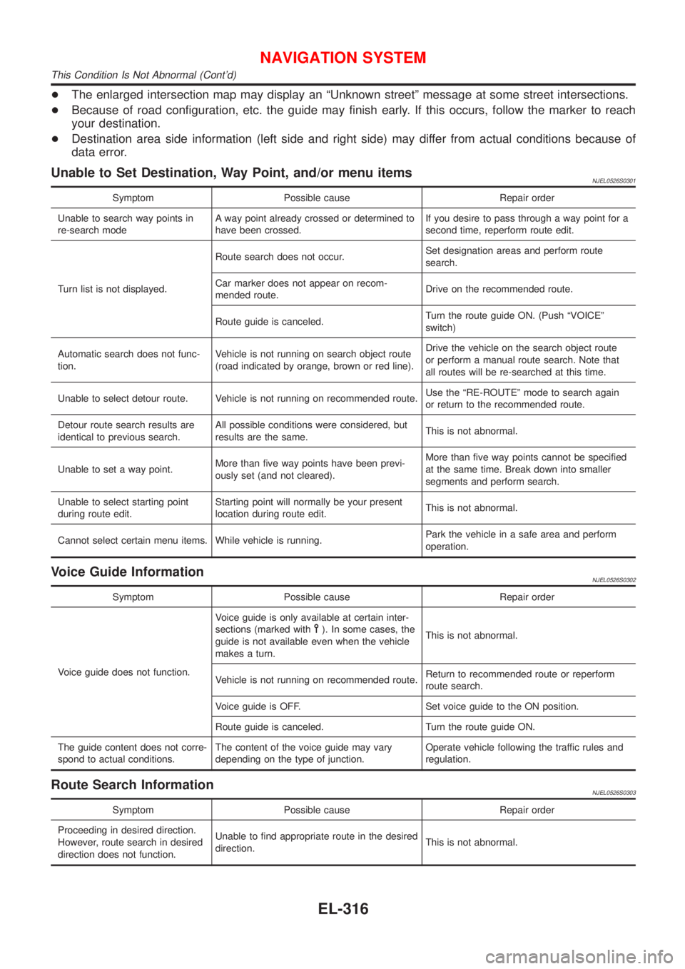
Unable to Set Destination, Way Point, and/or menu itemsNJEL0526S0301
Symptom Possible cause Repair order
Unable to search way points in
re-search modeA way point already crossed or determined to
have been crossed.If you desire to pass through a way point for a
second time, reperform route edit.
Turn list is not displayed.Route search does not occur.Set designation areas and perform route
search.
Car marker does not appear on recom-
mended route.Drive on the recommended route.
Route guide is canceled.Turn the route guide ON. (Push ªVOICEº
switch)
Automatic search does not func-
tion.Vehicle is not running on search object route
(road indicated by orange, brown or red line).Drive the vehicle on the search object route
or perform a manual route search. Note that
all routes will be re-searched at this time.
Unable to select detour route. Vehicle is not running on recommended route.Use the ªRE-ROUTEº mode to search again
or return to the recommended route.
Detour route search results are
identical to previous search.All possible conditions were considered, but
results are the same.This is not abnormal.
Unable to set a way point.More than five way points have been previ-
ously set (and not cleared).More than five way points cannot be specified
at the same time. Break down into smaller
segments and perform search.
Unable to select starting point
during route edit.Starting point will normally be your present
location during route edit.This is not abnormal.
Cannot select certain menu items. While vehicle is running.Park the vehicle in a safe area and perform
operation.
Voice Guide InformationNJEL0526S0302
Symptom Possible cause Repair order
Voice guide does not function.Voice guide is only available at certain inter-
sections (marked with
). In some cases, the
guide is not available even when the vehicle
makes a turn.This is not abnormal.
Vehicle is not running on recommended route.Return to recommended route or reperform
route search.
Voice guide is OFF. Set voice guide to the ON position.
Route guide is canceled. Turn the route guide ON.
The guide content does not corre-
spond to actual conditions.The content of the voice guide may vary
depending on the type of junction.Operate vehicle following the traffic rules and
regulation.
Route Search InformationNJEL0526S0303
Symptom Possible cause Repair order
Proceeding in desired direction.
However, route search in desired
direction does not function.Unable to find appropriate route in the desired
direction.This is not abnormal.
NAVIGATION SYSTEM
This Condition Is Not Abnormal (Cont'd)
EL-316
Page 2429 of 2493
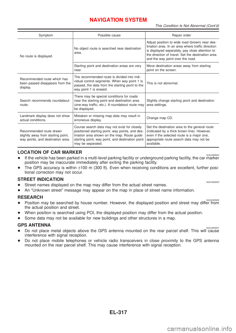
Symptom Possible cause Repair order
No route is displayed.No object route is searched near destination
area.Adjust position to wide road (brown) near des-
tination area. In an area where traffic direction
is displayed separately, pay close attention to
the direction of travel. Set the destination area
and the way point over the road.
Starting point and destination areas are very
near.Move destination areas away from starting
point on the screen.
Recommended route which has
been passed disappears from the
display.The recommended route is divided into indi-
vidual control segments. When way point 1 is
passed, the data from the starting point to the
way point 1 is erased.This is not abnormal.
Search recommends roundabout
route.There may be special conditions for roads
near the starting point and destination area
(one-way traffic, etc.). A roundabout route may
be displayed.Slightly change starting point and destination
area settings.
Landmark display does not show
actual conditions.Mistaken or missing map data may result in
erroneous display.Change map CD.
Recommended route drawn
slightly away from starting point,
way points, and destination area.Course search data may not exist for closely
positioned starting point, way points, and des-
tination area shown on the map. Route guide
starting point, way point, and destination point
may be separated.Set the destination area to the general route
(indicated by a thick brown line). However,
even if the selected route is a major one,
appropriate route search data may not be
available.
LOCATION OF CAR MARKERNJEL0526S04+If the vehicle has been parked in a multi-level parking facility or underground parking facility, the car marker
position may be inaccurate immediately after exiting the parking facility.
+The GPS accuracy is within±100 m (300 ft). Even when receiving conditions are excellent, further posi-
tional correction may not occur.
STREET INDICATIONNJEL0526S05+Street names displayed on the map may differ from the actual street names.
+An ªUnknown streetº message may appear on the map in place of street name information.
RESEARCHNJEL0526S06+Position may be searched by house number. However, the displayed position and street may differ from
the actual position and street.
+When position is searched using POI, the displayed position may differ from the actual position.
+Some data may not be available for new buildings and other structures in a map.
GPS ANTENNANJEL0526S07+Do not place metal objects above the GPS antenna mounted on the rear parcel shelf. This will cause
interference with signal reception.
+Do not place mobile telephones or vehicle radio transceivers in close proximity to the GPS antenna
mounted on the rear parcel shelf. This may cause interference with signal reception.
NAVIGATION SYSTEM
This Condition Is Not Abnormal (Cont'd)
EL-317
Page 2480 of 2493
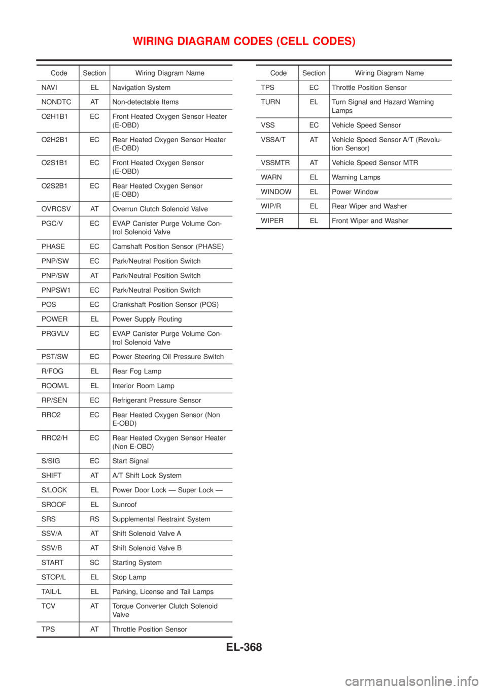
Code Section Wiring Diagram Name
NAVI EL Navigation System
NONDTC AT Non-detectable Items
O2H1B1 EC Front Heated Oxygen Sensor Heater
(E-OBD)
O2H2B1 EC Rear Heated Oxygen Sensor Heater
(E-OBD)
O2S1B1 EC Front Heated Oxygen Sensor
(E-OBD)
O2S2B1 EC Rear Heated Oxygen Sensor
(E-OBD)
OVRCSV AT Overrun Clutch Solenoid Valve
PGC/V EC EVAP Canister Purge Volume Con-
trol Solenoid Valve
PHASE EC Camshaft Position Sensor (PHASE)
PNP/SW EC Park/Neutral Position Switch
PNP/SW AT Park/Neutral Position Switch
PNPSW1 EC Park/Neutral Position Switch
POS EC Crankshaft Position Sensor (POS)
POWER EL Power Supply Routing
PRGVLV EC EVAP Canister Purge Volume Con-
trol Solenoid Valve
PST/SW EC Power Steering Oil Pressure Switch
R/FOG EL Rear Fog Lamp
ROOM/L EL Interior Room Lamp
RP/SEN EC Refrigerant Pressure Sensor
RRO2 EC Rear Heated Oxygen Sensor (Non
E-OBD)
RRO2/H EC Rear Heated Oxygen Sensor Heater
(Non E-OBD)
S/SIG EC Start Signal
SHIFT AT A/T Shift Lock System
S/LOCK EL Power Door Lock Ð Super Lock Ð
SROOF EL Sunroof
SRS RS Supplemental Restraint System
SSV/A AT Shift Solenoid Valve A
SSV/B AT Shift Solenoid Valve B
START SC Starting System
STOP/L EL Stop Lamp
TAIL/L EL Parking, License and Tail Lamps
TCV AT Torque Converter Clutch Solenoid
Valve
TPS AT Throttle Position SensorCode Section Wiring Diagram Name
TPS EC Throttle Position Sensor
TURN EL Turn Signal and Hazard Warning
Lamps
VSS EC Vehicle Speed Sensor
VSSA/T AT Vehicle Speed Sensor A/T (Revolu-
tion Sensor)
VSSMTR AT Vehicle Speed Sensor MTR
WARN EL Warning Lamps
WINDOW EL Power Window
WIP/R EL Rear Wiper and Washer
WIPER EL Front Wiper and Washer
WIRING DIAGRAM CODES (CELL CODES)
EL-368
Page 2487 of 2493

Shock absorber (rear) ............................... SU-21
Side air bag ............................................... RS-33
Side trim .................................................... BT-31
Spare tire size ............................................ GI-43
Speedometer ............................................. EL-89
Spiral cable ............................................... RS-29
Spot lamp .................................................. EL-87
Spring (Wheelarch) height .......................... SU-6
Stabilizer bar (front) ................................... SU-11
Stall test (A/T) ............................................ AT-78
Standardized relay ....................................... EL-7
Start signal ...................................... EC-460, 693
Starter ....................................................... SC-16
Starting system ......................................... SC-13
Steering linkage ......................................... ST-15
Steering switch .......................................... EL-39
Steering wheel and column ....................... ST-10
Steering wheel play ..................................... ST-6
Steering wheel turning force ....................... ST-8
Stop lamp .................................................. EL-56
Striking rod (M/T) .......................... MT-32, 56, 94
Strut (front) .................................................. SU-9
Strut (rear) ................................................. SU-20
Sub-gear (M/T) ................................... MT-31, 55
Sunroof, electric ....................................... EL-165
Sunroof ...................................................... BT-60
Super lock ................................................ EL-196
Supplemental Restraint System ............... RS-20
Supplemental restraint system - Wiring
diagram .................................................. RS-46
Symbols and abbreviations ........................ GI-11
Symptom matrix chart ..................... EC-124, 541
Synchronizer (M/T) ....................... MT-31, 55, 93
System readiness test (SRT) code ........... EC-60
T
TCM circuit diagram ................................... AT-17
TCM inspection table ............................... AT-117
TP/SW - Wiring diagram ................. EC-323, 427
TPS - Wiring diagram ............................. EC-171
TURN - Wiring diagram ............................. EL-67
Tachometer ................................................ EL-89
Tail lamp .................................................... EL-53
Thermostat .......................................... LC-15, 40
Three way catalyst precautions ................... GI-6
Three way catalyst .................................. EC-299
Throttle position sensor (TPS) ................ EC-168
Throttle position sensor adjustment .......... EC-98
Throttle position switch ........... AT-139, 264, 333,
EC-321, 426
Throwout bearing - See Clutch release
bearing ............................................. CL-17, 20
Tie-rod ball joints ....................................... ST-19
Tie-rod ........................................................ ST-15
Tightening torque of standard bolts ........... GI-49
Timing chain ....................................... EM-22, 93
Tire size ...................................................... GI-43
Torque converter installation .................... AT-347Tow truck towing ........................................ GI-47
Transmission case (M/T) .............. MT-30, 54, 92
Tread-FR&RR (Dimensions) ...................... GI-43
Trim ............................................................ BT-31
Trouble diagnoses ...................................... GI-31
Trunk lid finisher ........................................ BT-45
Trunk lid opener - See Trunk lid ................ BT-10
Trunk lid trim .............................................. BT-45
Trunk lid ..................................................... BT-10
Trunk room lamp ....................................... EL-87
Trunk room trim ......................................... BT-45
Turn signal lamp ........................................ EL-65
Two trip detection logic ............................. EC-57
Two-pole lift ................................................ GI-46
U
Under body ................................................ BT-77
V
VSS - Wiring diagram ..................... EC-311, 593
Vacuum hose (brake system) ................... BR-22
Vacuum hose drawing (Engine control) .... EC-27
Vacuum pump ........................................... BR-23
Valve clearance ................................ EM-42, 132
Valve guide ....................................... EM-38, 123
Valve lifter ................................................. EM-41
Valve seat ......................................... EM-40, 125
Valve spring ...................................... EM-41, 127
Vehicle speed sensor (VSS) ........... EC-309, 593
Viscosity number (SAE) ............................ MA-21
Viscous coupling (FF M/T) ........................ MT-93
W
WARN - Wiring diagram .......................... EL-108
WIP/R - Wiring diagram .......................... EL-129
WIPER - Wiring diagram ......................... EL-125
Warning chime ......................................... EL-113
Warning lamps ......................................... EL-107
Washer, front ........................................... EL-123
Water pump ......................................... LC-14, 38
Water temperature gauge .......................... EL-89
Weatherstrip - See Exterior ....................... BT-47
Wheel alignment (rear) ............................. SU-18
Wheel bearing (front) .................................. AX-3
Wheel bearing (rear) ................................. AX-23
Wheel hub (front) ........................................ AX-5
Wheel hub (rear) ....................................... AX-24
Wheel sensors (ABS) ............................... BR-88
Wheelarch height ........................................ SU-6
Wheelbase (Dimensions) ........................... GI-43
Wide open & closed throttle position
switch ................................................... EC-168
Width (Dimensions) .................................... GI-43
Window, rear .............................................. BT-68
ALPHABETICAL INDEX
IDX-7