2001 NISSAN ALMERA N16 wheel bolts
[x] Cancel search: wheel boltsPage 1744 of 2493
SBR219C
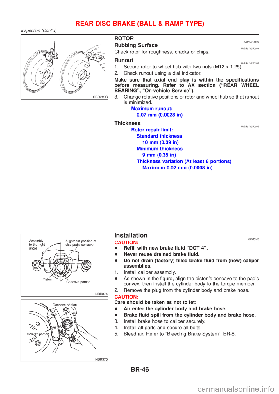
ROTORNJBR0145S02Rubbing SurfaceNJBR0145S0201Check rotor for roughness, cracks or chips.
RunoutNJBR0145S02021. Secure rotor to wheel hub with two nuts (M12 x 1.25).
2. Check runout using a dial indicator.
Make sure that axial end play is within the specifications
before measuring. Refer to AX section (ªREAR WHEEL
BEARINGº, ªOn-vehicle Serviceº).
3. Change relative positions of rotor and wheel hub so that runout
is minimized.
Maximum runout:
0.07 mm (0.0028 in)
ThicknessNJBR0145S0203Rotor repair limit:
Standard thickness
10 mm (0.39 in)
Minimum thickness
9 mm (0.35 in)
Thickness variation (At least 8 portions)
Maximum 0.02 mm (0.0008 in)
NBR374
NBR375
InstallationNJBR0146CAUTION:
+Refill with new brake fluid ªDOT 4º.
+Never reuse drained brake fluid.
+Do not drain (factory) filled brake fluid from (new) caliper
assemblies.
1. Install caliper assembly.
+As shown in the figure, align the piston's concave to the pad's
convex, then install the cylinder body to the torque member.
2. Remove the plug from the cylinder body and brake hose.
CAUTION:
Care should be taken as not to let:
+Air enter the cylinder body and brake hose.
+Brake fluid spill from the cylinder body and brake hose.
3. Install brake hose to caliper securely.
4. Install all parts and secure all bolts.
5. Bleed air. Refer to ªBleeding Brake Systemº, BR-8.
REAR DISC BRAKE (BALL & RAMP TYPE)
Inspection (Cont'd)
BR-46
Page 1801 of 2493
SRS266
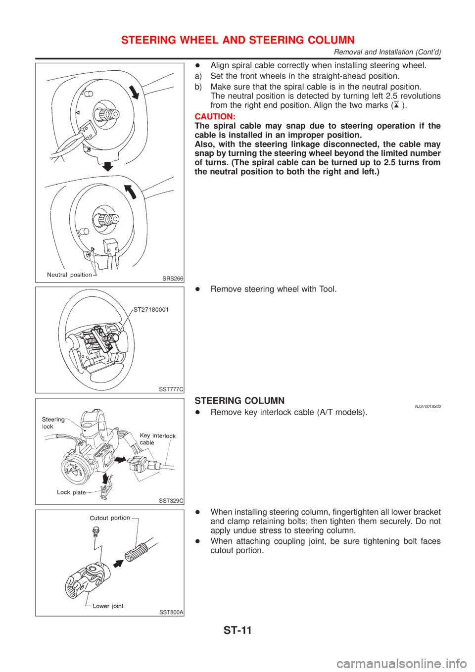
+Align spiral cable correctly when installing steering wheel.
a) Set the front wheels in the straight-ahead position.
b) Make sure that the spiral cable is in the neutral position.
The neutral position is detected by turning left 2.5 revolutions
from the right end position. Align the two marks (
).
CAUTION:
The spiral cable may snap due to steering operation if the
cable is installed in an improper position.
Also, with the steering linkage disconnected, the cable may
snap by turning the steering wheel beyond the limited number
of turns. (The spiral cable can be turned up to 2.5 turns from
the neutral position to both the right and left.)
SST777C
+Remove steering wheel with Tool.
SST329C
STEERING COLUMNNJST0018S02+Remove key interlock cable (A/T models).
SST800A
+When installing steering column, fingertighten all lower bracket
and clamp retaining bolts; then tighten them securely. Do not
apply undue stress to steering column.
+When attaching coupling joint, be sure tightening bolt faces
cutout portion.
STEERING WHEEL AND STEERING COLUMN
Removal and Installation (Cont'd)
ST-11
Page 1806 of 2493
Removal and InstallationNJST0022
SST878CA
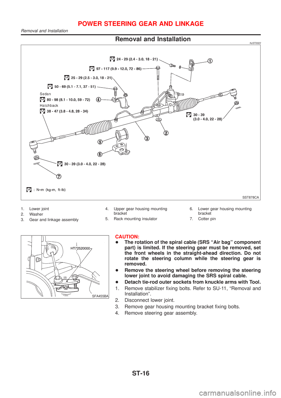
1. Lower joint
2. Washer
3. Gear and linkage assembly4. Upper gear housing mounting
bracket
5. Rack mounting insulator6. Lower gear housing mounting
bracket
7. Cotter pin
SFA455BA
CAUTION:
+The rotation of the spiral cable (SRS ªAir bagº component
part) is limited. If the steering gear must be removed, set
the front wheels in the straight-ahead direction. Do not
rotate the steering column while the steering gear is
removed.
+Remove the steering wheel before removing the steering
lower joint to avoid damaging the SRS spiral cable.
+Detach tie-rod outer sockets from knuckle arms with Tool.
1. Remove stabilizer fixing bolts. Refer to SU-11, ªRemoval and
Installationº.
2. Disconnect lower joint.
3. Remove gear housing mounting bracket fixing bolts.
4. Remove steering gear assembly.
POWER STEERING GEAR AND LINKAGE
Removal and Installation
ST-16
Page 1807 of 2493
SST879C
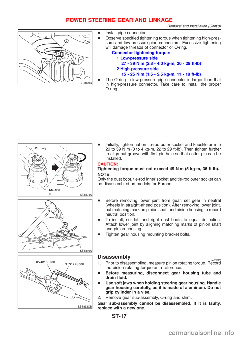
+Install pipe connector.
+Observe specified tightening torque when tightening high-pres-
sure and low-pressure pipe connectors. Excessive tightening
will damage threads of connector or O-ring.
Connector tightening torque:
1 Low-pressure side
27 - 39 N´m (2.8 - 4.0 kg-m, 20 - 29 ft-lb)
2 High-pressure side
15 - 25 N´m (1.5 - 2.5 kg-m, 11 - 18 ft-lb)
+The O-ring in low-pressure pipe connector is larger than that
in high-pressure connector. Take care to install the proper
O-ring.
SST824A
+Initially, tighten nut on tie-rod outer socket and knuckle arm to
29 to 39 N´m (3 to 4 kg-m, 22 to 29 ft-lb). Then tighten further
to align nut groove with first pin hole so that cotter pin can be
installed.
CAUTION:
Tightening torque must not exceed 49 N´m (5 kg-m, 36 ft-lb).
NOTE:
Only the dust boot, tie-rod inner socket and tie-rod outer socket can
be disassembled on models for Europe.
SST819A
+Before removing lower joint from gear, set gear in neutral
(wheels in straight-ahead position). After removing lower joint,
put matching mark on pinion shaft and pinion housing to record
neutral position.
+To install, set left and right dust boots to equal deflection.
Attach lower joint by aligning matching marks of pinion shaft
and pinion housing.
+Tighten gear housing mounting bracket bolts.
SST862CB
DisassemblyNJST00231. Prior to disassembling, measure pinion rotating torque. Record
the pinion rotating torque as a reference.
+Before measuring, disconnect gear housing tube and
drain fluid.
+Use soft jaws when holding steering gear housing. Handle
gear housing carefully, as it is made of aluminum. Do not
grip cylinder in a vise.
2. Remove gear sub-assembly, O-ring and shim.
Gear sub-assembly cannot be disassembled. If it is faulty,
replace with a new one.
POWER STEERING GEAR AND LINKAGE
Removal and Installation (Cont'd)
ST-17
Page 1823 of 2493
Precautions
SUPPLEMENTAL RESTRAINT SYSTEM (SRS) ªAIR BAGº AND ªSEAT BELT
PRE-TENSIONERº
NJRS0001The Supplemental Restraint System such as ªAIR BAGº and ªSEAT BELT PRE-TENSIONERº used along with
a seat belt, helps to reduce the risk or severity of injury to the driver and front passenger for certain types of
collision. The SRS composition which is available to NISSAN MODEL N16 is as follows (The composition
varies according to the destination and optional equipment.):
+For a frontal collision
The Supplemental Restraint System consists of driver's air bag module (located in the center of the steer-
ing wheel), front passenger air bag module (located on the instrument panel on passenger side), front seat
belt pre-tensioners, a diagnosis sensor unit, warning lamp, wiring harness and spiral cable.
+For a side collision
The Supplemental Restraint System consists of front side air bag module (located in the outer side of front
seat), side air bag (satellite) sensor, diagnosis sensor unit (one of components of air bags for a frontal
collision), wiring harness, warning lamp (one of components of air bags for a frontal collision).
WARNING:
+To avoid rendering the SRS inoperative, which could increase the risk of personal injury or death
in the event of a collision which would result in air bag inflation, all maintenance should be per-
formed by an authorized NISSAN dealer.
+Improper maintenance, including incorrect removal and installation of the SRS, can lead to per-
sonal injury caused by unintentional activation of the system.
+Do not use electrical test equipment on any circuit related to the SRS unless instructed to in this
Service Manual. SRS wiring harnesses can be identified by yellow harness connector.
PRECAUTION FOR SEAT BELT SERVICENJRS0002CAUTION:
+Before removing the seat belt pre-tensioner assembly, turn the ignition switch off, disconnect both
battery cables and wait at least 3 minutes.
+Do not use electrical test equipment for seat belt pre-tensioner connector.
+After replacing or reinstalling seat belt pre-tensioner assembly, or reconnecting seat belt pre-ten-
sioner connector, check the system function. Refer to ªSRS Operation Checkº for details. (RS-49)
+Do not disassemble buckle or seat belt assembly.
+Replace anchor bolts if they are deformed or worn out.
+Never oil tongue and buckle.
+If any component of seat belt assembly is questionable, do not repair. Replace the whole seat belt
assembly.
+If webbing is cut, frayed, or damaged, replace seat belt assembly.
+When replacing seat belt assembly, use a genuine seat belt assembly.
After A CollisionNJRS0002S01WARNING:
Inspect all seat belt assemblies including retractors and attaching hardware after any collision.
NISSAN recommends that all seat belt assemblies in use during a collision be replaced unless the
collision was minor and the belts show no damage and continue to operate properly. Failure to do so
could result in serious personal injury in an accident. Seat belt assemblies not in use during a colli-
sion should also be replaced if either damage or improper operation is noted. Seat belt pre-tensioner
should be replaced even if the seat belts are not in use during a frontal collision in which the air bags
are deployed.
Replace any seat belt assembly (including anchor bolts) if:
+The seat belt was in use at the time of a collision (except for minor collisions and the belts, retractors and
buckles show no damage and continue to operate properly).
+The seat belt was damaged in an accident. (i.e. torn webbing, bent retractor or guide, etc.)
+The seat belt attaching point was damaged in an accident. Inspect the seat belt attaching area for dam-
age or distortion and repair as necessary before installing a new seat belt assembly.
+Anchor bolts are deformed or worn out.
+The seat belt pre-tensioner should be replaced even if the seat belts are not in use during the collision in
which the air bags are deployed.
SEAT BELTS
Precautions
RS-3
Page 1845 of 2493
SRS797-A
Maintenance ItemsNJRS0012CAUTION:
Do not use electrical test equipment to check SRS circuit.
1. Check operation of ªAIR BAGº warning lamp.
After turning ignition key to ªONº position, ªAIR BAGº warning
lamp illuminates. The ªAIR BAGº warning lamp will go off after
about 7 seconds if no malfunction is detected. If any of the fol-
lowing ªAIR BAGº warning lamp conditions occur, immediately
check the air bag system. Refer to RS-49 for details.
+The ªAIR BAGº warning lamp does not illuminate when the
ignition switch is turned ªONº.
+The ªAIR BAGº warning lamp does not go off about 7 seconds
after the ignition switch is turned ªONº.
+The ªAIR BAGº warning lamp blinks after about 7 seconds after
the ignition switch is turned ªONº.
2. Visually check SRS components.
1) Diagnosis sensor unit
+Check diagnosis sensor unit and bracket for dents, cracks and
deformities.
+Check connectors for damage, and terminals for deformities.
2) Air bag module and steering wheel
+Remove air bag module from steering wheel, instrument panel
or seatback. Check harness cover and connectors for damage,
terminals for deformities, and harness for binding.
+Install driver air bag module to steering wheel to check fit or
alignment with the wheel.
+Check steering wheel for excessive free play.
+Install front passenger air bag module to instrument panel to
check fit or alignment with the instrument panel.
+Install front side air bag module to seatback to check fit and
alignment with the seat.
3) Spiral cable
+Check spiral cable for dents, cracks, or deformities.
+Check connectors and protective tape for damage.
+Check steering wheel for noise, binding or heavy operation.
4) Main harness, body harness, side air bag module sub-harness
+Check connectors for poor connections, damage, and termi-
nals for deformities.
+Check harnesses for binding, chafing or cut.
5) Front seat belt pre-tensioner
+Check harness cover and connectors for damage, terminals
for deformities, and harness for binding.
+Check belts for damage and anchors for loose mounting.
+Check retractor for smooth operation.
+Perform self-diagnosis for seat belt pre-tensioner using ªAIR
BAGº warning lamp or CONSULT-II.
Refer to ªSRS Operation Checkº for details. (RS-49)
6) Side air bag (satellite) sensor
+Check side air bag (satellite) sensor (including bracket portion)
for dents, cracks or deformities.
+Check connectors for damage, and terminals for deformities.
CAUTION:
Replace previously used special bolts, hex bolts and ground
bolt with new ones.
SUPPLEMENTAL RESTRAINT SYSTEM (SRS)
Maintenance Items
RS-25
Page 1849 of 2493
Driver Air Bag Module and Spiral Cable
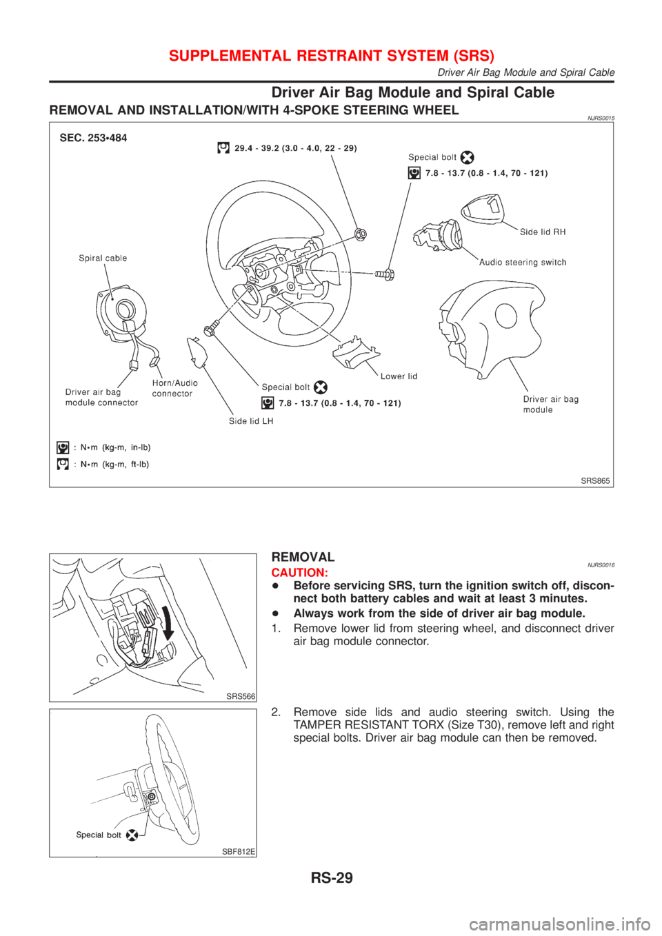
REMOVAL AND INSTALLATION/WITH 4-SPOKE STEERING WHEELNJRS0015
SRS865
SRS566
REMOVALNJRS0016CAUTION:
+Before servicing SRS, turn the ignition switch off, discon-
nect both battery cables and wait at least 3 minutes.
+Always work from the side of driver air bag module.
1. Remove lower lid from steering wheel, and disconnect driver
air bag module connector.
SBF812E
2. Remove side lids and audio steering switch. Using the
TAMPER RESISTANT TORX (Size T30), remove left and right
special bolts. Driver air bag module can then be removed.
SUPPLEMENTAL RESTRAINT SYSTEM (SRS)
Driver Air Bag Module and Spiral Cable
RS-29
Page 1850 of 2493
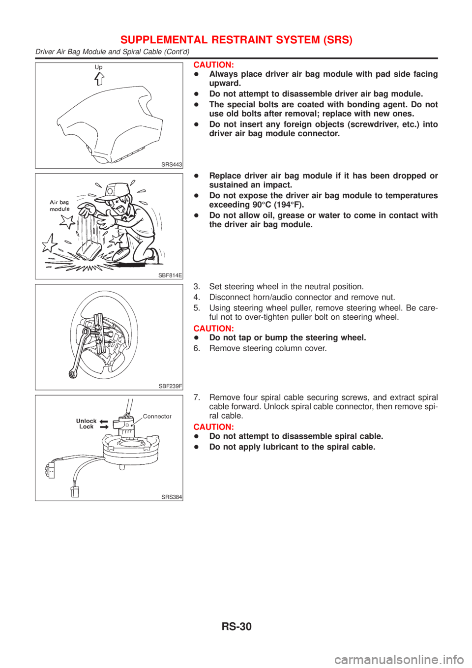
SRS443
CAUTION:
+Always place driver air bag module with pad side facing
upward.
+Do not attempt to disassemble driver air bag module.
+The special bolts are coated with bonding agent. Do not
use old bolts after removal; replace with new ones.
+Do not insert any foreign objects (screwdriver, etc.) into
driver air bag module connector.
SBF814E
+Replace driver air bag module if it has been dropped or
sustained an impact.
+Do not expose the driver air bag module to temperatures
exceeding 90ÉC (194ÉF).
+Do not allow oil, grease or water to come in contact with
the driver air bag module.
SBF239F
3. Set steering wheel in the neutral position.
4. Disconnect horn/audio connector and remove nut.
5. Using steering wheel puller, remove steering wheel. Be care-
ful not to over-tighten puller bolt on steering wheel.
CAUTION:
+Do not tap or bump the steering wheel.
6. Remove steering column cover.
SRS384
7. Remove four spiral cable securing screws, and extract spiral
cable forward. Unlock spiral cable connector, then remove spi-
ral cable.
CAUTION:
+Do not attempt to disassemble spiral cable.
+Do not apply lubricant to the spiral cable.
SUPPLEMENTAL RESTRAINT SYSTEM (SRS)
Driver Air Bag Module and Spiral Cable (Cont'd)
RS-30