Page 1650 of 2493
SFA898A
2. Remove brake caliper assembly and rotor.
Brake hose need not be disconnected from brake caliper. In
this case, suspend caliper assembly with wire so as not to
stretch brake hose. Be careful not to depress brake pedal, or
piston will pop out.
Make sure brake hose is not twisted.
SFA372-A
3. Separate tie-rod from knuckle with Tool.
Install stud nut on stud bolt to prevent damage to stud bolt.
SFA181A
4. Separate drive shaft from knuckle by lightly tapping it. If it is
hard to remove, use a puller.
Cover boots with shop towel so as not to damage them when
removing drive shaft.
SFA153B
5. Remove strut lower mounting bolts.
SFA113AC
6. Loosen lower ball joint tightening nut.
7. Separate knuckle from lower ball joint stud with Tool.
8. Remove knuckle from transverse link.
FRONT AXLE
Wheel Hub and Knuckle (Cont'd)
AX-6
Page 1651 of 2493
SFA114A
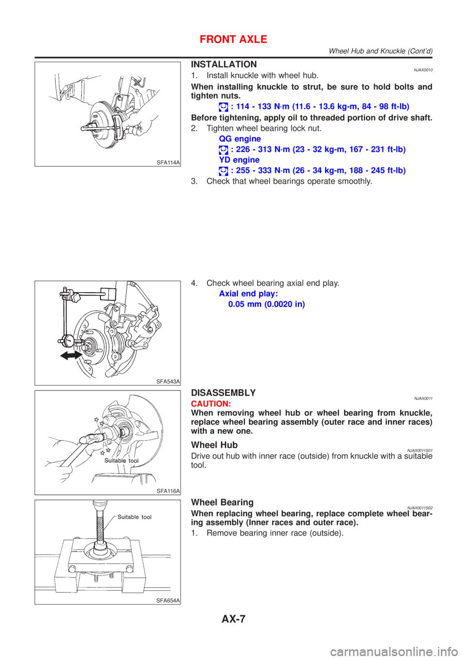
INSTALLATIONNJAX00101. Install knuckle with wheel hub.
When installing knuckle to strut, be sure to hold bolts and
tighten nuts.
: 114 - 133 N´m (11.6 - 13.6 kg-m, 84 - 98 ft-lb)
Before tightening, apply oil to threaded portion of drive shaft.
2. Tighten wheel bearing lock nut.
QG engine
: 226 - 313 N´m (23 - 32 kg-m, 167 - 231 ft-lb)
YD engine
: 255 - 333 N´m (26 - 34 kg-m, 188 - 245 ft-lb)
3. Check that wheel bearings operate smoothly.
SFA543A
4. Check wheel bearing axial end play.
Axial end play:
0.05 mm (0.0020 in)
SFA116A
DISASSEMBLYNJAX0011CAUTION:
When removing wheel hub or wheel bearing from knuckle,
replace wheel bearing assembly (outer race and inner races)
with a new one.
Wheel HubNJAX0011S01Drive out hub with inner race (outside) from knuckle with a suitable
tool.
SFA654A
Wheel BearingNJAX0011S02When replacing wheel bearing, replace complete wheel bear-
ing assembly (Inner races and outer race).
1. Remove bearing inner race (outside).
FRONT AXLE
Wheel Hub and Knuckle (Cont'd)
AX-7
Page 1655 of 2493
SFA090A
REMOVALNJAX00141. Remove wheel bearing lock nut.
Brake caliper need not be disconnected. Do not twist or
stretch brake hose when moving components.
SFA153B
2. Remove strut lower mount bolts.
3. Remove brake hose clip.
SFA499A
4. Separate drive shaft from knuckle by lightly tapping it. If it is
hard to remove, use a puller.
Cover boots with shop towel so as not to damage them
when removing drive shaft.
Refer to ªWheel Hub and Knuckleº, ªFRONT AXLEº, AX-5.
5. Remove right drive shaft from transaxle.
SAX012
6. Remove left drive shaft from transaxle.
Ð For M/T models Ð
+Pry off drive shaft from transaxle as shown at left.
FRONT AXLE
Drive Shaft (Cont'd)
AX-11
Page 1678 of 2493
SMA525A
On-vehicle Service
FRONT SUSPENSION PARTSNJSU0006Check front axle and front suspension parts for excessive play,
cracks, wear or other damage.
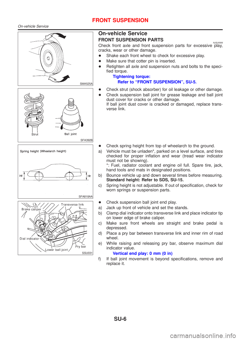
+Shake each front wheel to check for excessive play.
+Make sure that cotter pin is inserted.
+Retighten all axle and suspension nuts and bolts to the speci-
fied torque.
Tightening torque:
Refer to ªFRONT SUSPENSIONº, SU-5.
SFA392B
+Check strut (shock absorber) for oil leakage or other damage.
+Check suspension ball joint for grease leakage and ball joint
dust cover for cracks or other damage.
If ball joint dust cover is cracked or damaged, replace trans-
verse link.
SFA818AA
+Check spring height from top of wheelarch to the ground.
a) Vehicle must be unladen*, parked on a level surface, and tires
checked for proper inflation and wear (tread wear indicator
must not be showing).
*: Fuel, radiator coolant and engine oil full. Spare tire, jack,
hand tools and mats in designated positions.
b) Bounce vehicle up and down several times before measuring.
Standard height: Refer to SDS, SU-15.
c) Spring height is not adjustable. If out of specification, check for
worn springs or suspension parts.
SSU031
+Check suspension ball joint end play.
a) Jack up front of vehicle and set the stands.
b) Clamp dial indicator onto transverse link and place indicator tip
on lower edge of brake caliper.
c) Make sure front wheels are straight and brake pedal is
depressed.
d) Place a pry bar between transverse link and inner rim of road
wheel.
e) While raising and releasing pry bar, observe maximum dial
indicator value.
Vertical end play: 0 mm (0 in)
f) If ball joint movement is beyond specifications, remove and
replace it.
FRONT SUSPENSION
On-vehicle Service
SU-6
Page 1684 of 2493
SFA449BB
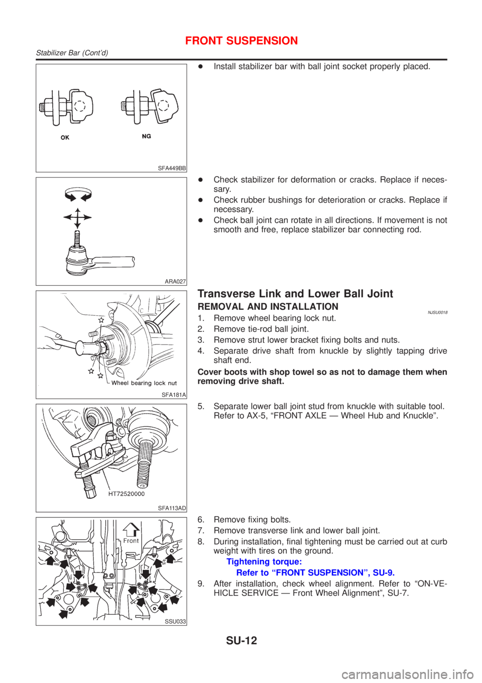
+Install stabilizer bar with ball joint socket properly placed.
ARA027
+Check stabilizer for deformation or cracks. Replace if neces-
sary.
+Check rubber bushings for deterioration or cracks. Replace if
necessary.
+Check ball joint can rotate in all directions. If movement is not
smooth and free, replace stabilizer bar connecting rod.
SFA181A
Transverse Link and Lower Ball Joint
REMOVAL AND INSTALLATIONNJSU00181. Remove wheel bearing lock nut.
2. Remove tie-rod ball joint.
3. Remove strut lower bracket fixing bolts and nuts.
4. Separate drive shaft from knuckle by slightly tapping drive
shaft end.
Cover boots with shop towel so as not to damage them when
removing drive shaft.
SFA113AD
5. Separate lower ball joint stud from knuckle with suitable tool.
Refer to AX-5, ªFRONT AXLE Ð Wheel Hub and Knuckleº.
SSU033
6. Remove fixing bolts.
7. Remove transverse link and lower ball joint.
8. During installation, final tightening must be carried out at curb
weight with tires on the ground.
Tightening torque:
Refer to ªFRONT SUSPENSIONº, SU-9.
9. After installation, check wheel alignment. Refer to ªON-VE-
HICLE SERVICE Ð Front Wheel Alignmentº, SU-7.
FRONT SUSPENSION
Stabilizer Bar (Cont'd)
SU-12
Page 1690 of 2493
SMA525A
On-vehicle Service
REAR SUSPENSION PARTSNJSU0029Check axle and suspension parts for excessive play, wear or dam-
age.
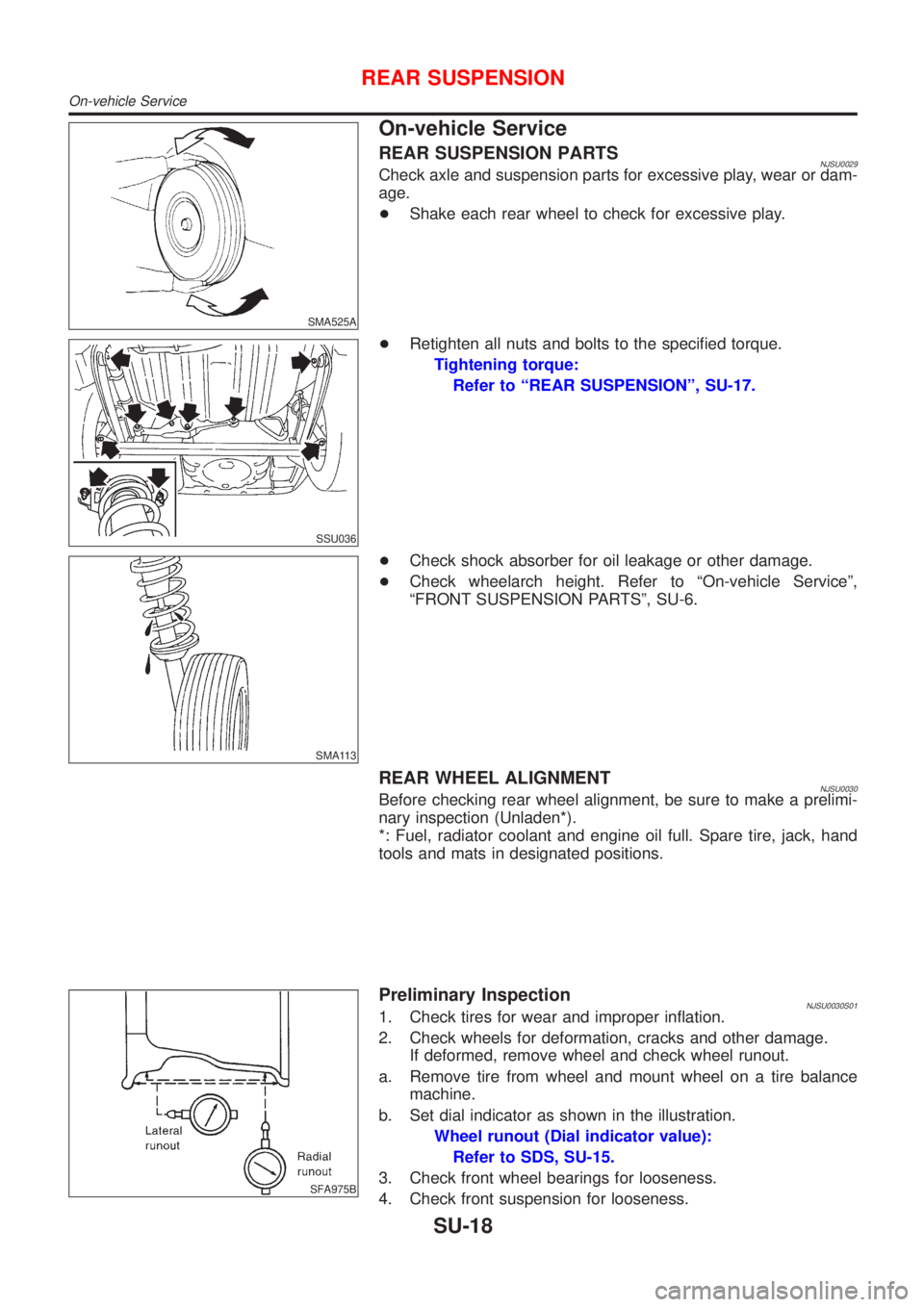
+Shake each rear wheel to check for excessive play.
SSU036
+Retighten all nuts and bolts to the specified torque.
Tightening torque:
Refer to ªREAR SUSPENSIONº, SU-17.
SMA113
+Check shock absorber for oil leakage or other damage.
+Check wheelarch height. Refer to ªOn-vehicle Serviceº,
ªFRONT SUSPENSION PARTSº, SU-6.
REAR WHEEL ALIGNMENTNJSU0030Before checking rear wheel alignment, be sure to make a prelimi-
nary inspection (Unladen*).
*: Fuel, radiator coolant and engine oil full. Spare tire, jack, hand
tools and mats in designated positions.
SFA975B
Preliminary InspectionNJSU0030S011. Check tires for wear and improper inflation.
2. Check wheels for deformation, cracks and other damage.
If deformed, remove wheel and check wheel runout.
a. Remove tire from wheel and mount wheel on a tire balance
machine.
b. Set dial indicator as shown in the illustration.
Wheel runout (Dial indicator value):
Refer to SDS, SU-15.
3. Check front wheel bearings for looseness.
4. Check front suspension for looseness.
REAR SUSPENSION
On-vehicle Service
SU-18
Page 1693 of 2493
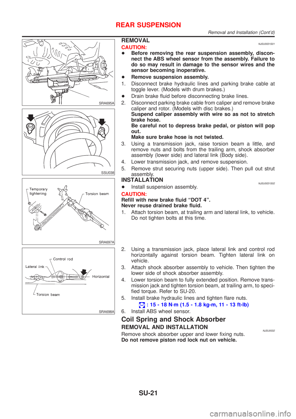
SRA695A
SSU038
REMOVALNJSU0031S01CAUTION:
+Before removing the rear suspension assembly, discon-
nect the ABS wheel sensor from the assembly. Failure to
do so may result in damage to the sensor wires and the
sensor becoming inoperative.
+Remove suspension assembly.
1. Disconnect brake hydraulic lines and parking brake cable at
toggle lever. (Models with drum brakes.)
+Drain brake fluid before disconnecting brake lines.
2. Disconnect parking brake cable from caliper and remove brake
caliper and rotor. (Models with disc brakes.)
Suspend caliper assembly with wire so as not to stretch
brake hose.
Be careful not to depress brake pedal, or piston will pop
out.
Make sure brake hose is not twisted.
3. Using a transmission jack, raise torsion beam a little, and
remove nuts and bolts from the trailing arm, shock absorber
assembly (lower side) and lateral link (Body side).
4. Lower transmission jack, and remove suspension.
5. Remove strut securing nuts (upper side). Then pull out strut
assembly.
SRA697A
INSTALLATIONNJSU0031S02+Install suspension assembly.
CAUTION:
Refill with new brake fluid ªDOT 4º.
Never reuse drained brake fluid.
1. Attach torsion beam, at trailing arm and lateral link, to vehicle.
Do not tighten bolts at this time.
SRA698A
2. Using a transmission jack, place lateral link and control rod
horizontally against torsion beam. Tighten lateral link on
vehicle.
3. Attach shock absorber assembly to vehicle. Then tighten the
lower side of shock absorber assembly.
4. Lower torsion beam to fully extended position. Remove trans-
mission jack and tighten torsion beam, at trailing arm, to speci-
fied torque. Refer to SU-20.
5. Install brake hydraulic lines and tighten flare nuts.
: 15 - 18 N´m (1.5 - 1.8 kg-m, 11 - 13 ft-lb)
6. Install ABS wheel sensor.
Coil Spring and Shock Absorber
REMOVAL AND INSTALLATIONNJSU0032Remove shock absorber upper and lower fixing nuts.
Do not remove piston rod lock nut on vehicle.
REAR SUSPENSION
Removal and Installation (Cont'd)
SU-21
Page 1730 of 2493
SBR617E
1. Release parking brake lever fully, then remove drum.
If drum is hard to remove, the following procedures
should be carried out.
a.Remove plug. To make shoe clearance, push shoe hold-
down spring to free toggle lever.
SBR020A
b.Install two bolts as shown. Tighten the two bolts gradually.
SBR214B
2. After removing retainer, remove spring by rotating shoes.
+Be careful not to damage wheel cylinder piston boots.
+Be careful not to damage parking brake cable when sepa-
rating it.
3. Remove adjuster.
4. Disconnect parking brake cable from toggle lever.
SBR329C
5. Remove retainer ring with a suitable tool. Then separate toggle
lever and brake shoe.
SBR330C
Inspection Ð Wheel CylinderNJBR0130+Check wheel cylinder for leakage.
+Check for wear, damage and loose conditions. Replace if any
such condition exists.
REAR DRUM BRAKE
Removal (Cont'd)
BR-32