2001 NISSAN ALMERA N16 wheel bolts
[x] Cancel search: wheel boltsPage 1851 of 2493

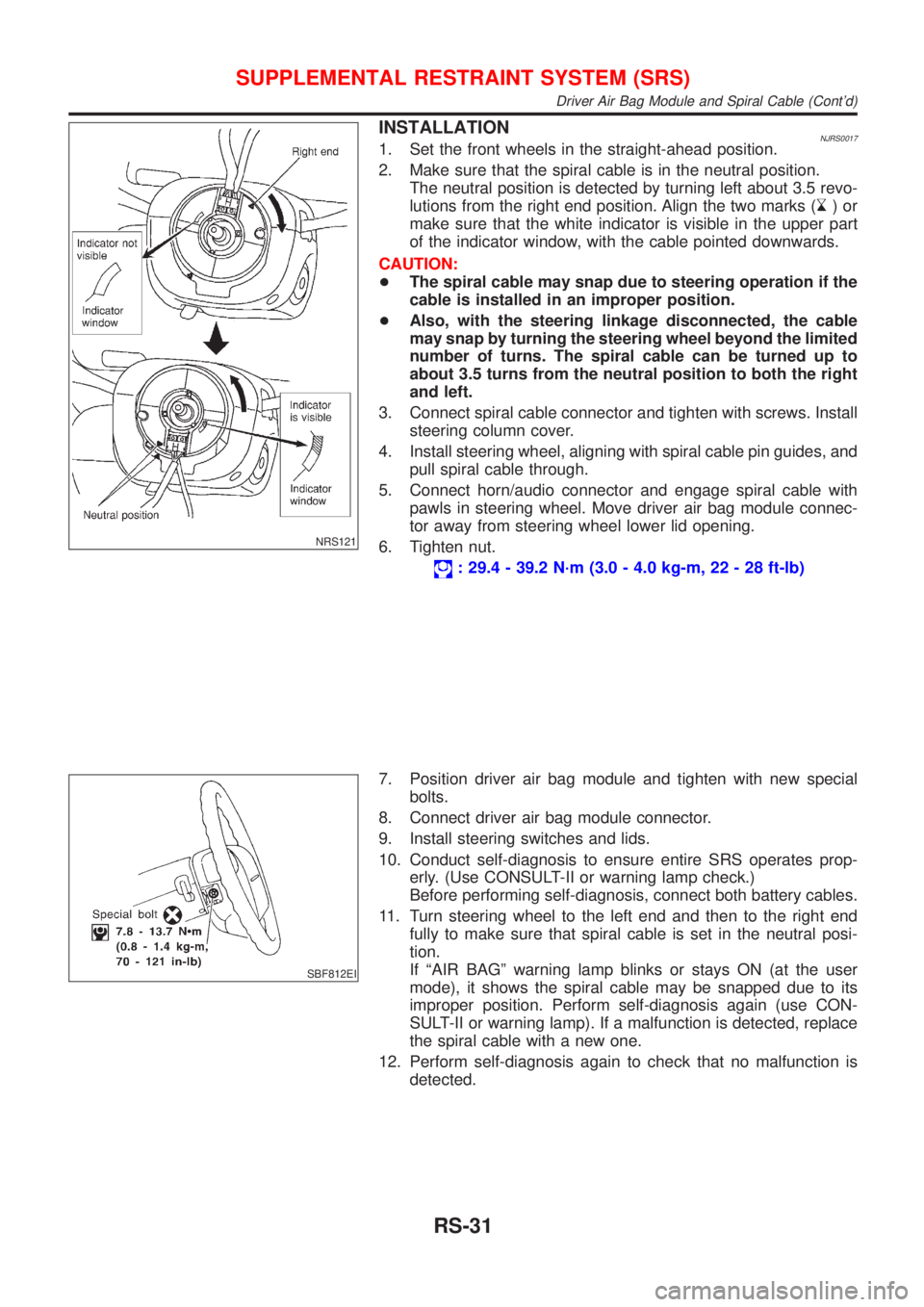
NRS121
INSTALLATIONNJRS00171. Set the front wheels in the straight-ahead position.
2. Make sure that the spiral cable is in the neutral position.
The neutral position is detected by turning left about 3.5 revo-
lutions from the right end position. Align the two marks (
)or
make sure that the white indicator is visible in the upper part
of the indicator window, with the cable pointed downwards.
CAUTION:
+The spiral cable may snap due to steering operation if the
cable is installed in an improper position.
+Also, with the steering linkage disconnected, the cable
may snap by turning the steering wheel beyond the limited
number of turns. The spiral cable can be turned up to
about 3.5 turns from the neutral position to both the right
and left.
3. Connect spiral cable connector and tighten with screws. Install
steering column cover.
4. Install steering wheel, aligning with spiral cable pin guides, and
pull spiral cable through.
5. Connect horn/audio connector and engage spiral cable with
pawls in steering wheel. Move driver air bag module connec-
tor away from steering wheel lower lid opening.
6. Tighten nut.
: 29.4 - 39.2 N´m (3.0 - 4.0 kg-m, 22 - 28 ft-lb)
SBF812EI
7. Position driver air bag module and tighten with new special
bolts.
8. Connect driver air bag module connector.
9. Install steering switches and lids.
10. Conduct self-diagnosis to ensure entire SRS operates prop-
erly. (Use CONSULT-II or warning lamp check.)
Before performing self-diagnosis, connect both battery cables.
11. Turn steering wheel to the left end and then to the right end
fully to make sure that spiral cable is set in the neutral posi-
tion.
If ªAIR BAGº warning lamp blinks or stays ON (at the user
mode), it shows the spiral cable may be snapped due to its
improper position. Perform self-diagnosis again (use CON-
SULT-II or warning lamp). If a malfunction is detected, replace
the spiral cable with a new one.
12. Perform self-diagnosis again to check that no malfunction is
detected.
SUPPLEMENTAL RESTRAINT SYSTEM (SRS)
Driver Air Bag Module and Spiral Cable (Cont'd)
RS-31
Page 1891 of 2493

Collision Diagnosis=NJRS0033FOR FRONTAL COLLISIONNJRS0033S07To repair the SRS, perform the following steps.
When SRS (except the side air bag) is activated in a collision:
1) Replace the diagnosis sensor unit.
2) Remove the air bag modules (except the side air bag module) and front seat belt pre-tensioner assem-
blies.
3) Check the SRS components using the table shown below:
+Replace any SRS components showing visible signs of damage (dents, cracks and deformation).
4) Install new air bag modules (except the side air bag module) and front seat belt pre-tensioner assemblies.
5) Conduct self-diagnosis using CONSULT-II or ªAIR BAGº warning lamp. Refer to ªSRS Operation Checkº
for details (RS-49). Ensure entire SRS operation properly.
When SRS is not activated in a collision:
1) Check the SRS components using the table shown below:
+Replace any SRS components showing visible signs of damage (dents, cracks and deformation).
2) Conduct self-diagnosis using CONSULT-II or ªAIR BAGº warning lamp. Refer to ªSRS Operation Checkº
for details (RS-49). Ensure entire SRS operation properly.
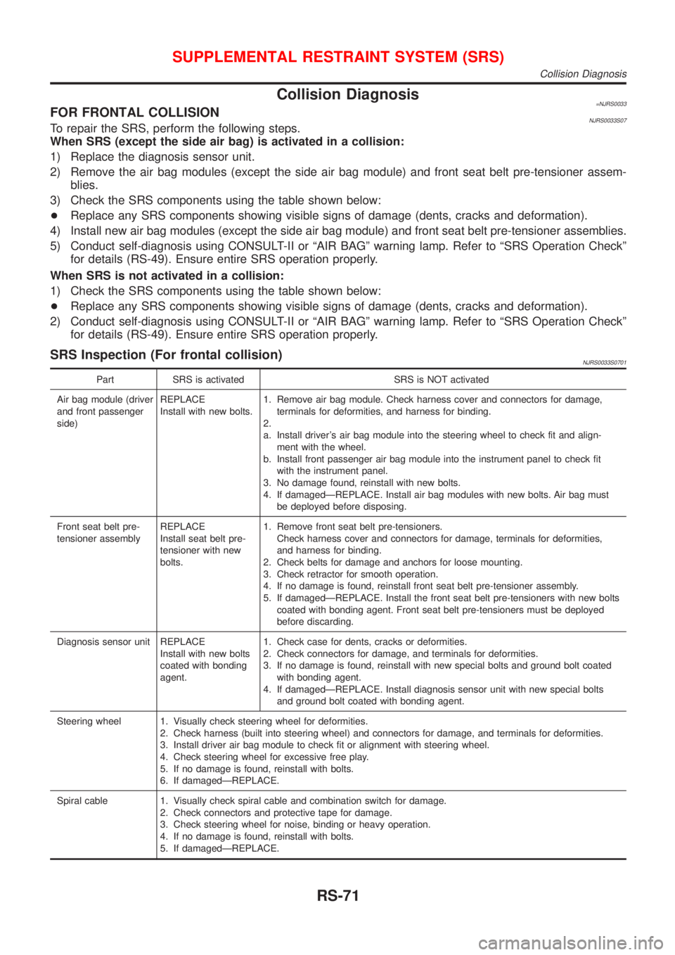
SRS Inspection (For frontal collision)NJRS0033S0701
Part SRS is activated SRS is NOT activated
Air bag module (driver
and front passenger
side)REPLACE
Install with new bolts.1. Remove air bag module. Check harness cover and connectors for damage,
terminals for deformities, and harness for binding.
2.
a. Install driver's air bag module into the steering wheel to check fit and align-
ment with the wheel.
b. Install front passenger air bag module into the instrument panel to check fit
with the instrument panel.
3. No damage found, reinstall with new bolts.
4. If damagedÐREPLACE. Install air bag modules with new bolts. Air bag must
be deployed before disposing.
Front seat belt pre-
tensioner assemblyREPLACE
Install seat belt pre-
tensioner with new
bolts.1. Remove front seat belt pre-tensioners.
Check harness cover and connectors for damage, terminals for deformities,
and harness for binding.
2. Check belts for damage and anchors for loose mounting.
3. Check retractor for smooth operation.
4. If no damage is found, reinstall front seat belt pre-tensioner assembly.
5. If damagedÐREPLACE. Install the front seat belt pre-tensioners with new bolts
coated with bonding agent. Front seat belt pre-tensioners must be deployed
before discarding.
Diagnosis sensor unit REPLACE
Install with new bolts
coated with bonding
agent.1. Check case for dents, cracks or deformities.
2. Check connectors for damage, and terminals for deformities.
3. If no damage is found, reinstall with new special bolts and ground bolt coated
with bonding agent.
4. If damagedÐREPLACE. Install diagnosis sensor unit with new special bolts
and ground bolt coated with bonding agent.
Steering wheel 1. Visually check steering wheel for deformities.
2. Check harness (built into steering wheel) and connectors for damage, and terminals for deformities.
3. Install driver air bag module to check fit or alignment with steering wheel.
4. Check steering wheel for excessive free play.
5. If no damage is found, reinstall with bolts.
6. If damagedÐREPLACE.
Spiral cable 1. Visually check spiral cable and combination switch for damage.
2. Check connectors and protective tape for damage.
3. Check steering wheel for noise, binding or heavy operation.
4. If no damage is found, reinstall with bolts.
5. If damagedÐREPLACE.
SUPPLEMENTAL RESTRAINT SYSTEM (SRS)
Collision Diagnosis
RS-71
Page 1901 of 2493

Removal and InstallationNJBT0004+When removing or installing hood, place a cloth or other padding on hood. This prevents vehicle body from
being scratched.
+Bumper fascia is made of plastic. Do not use excessive force and be sure to keep oil away from it.
+Hood adjustment: Adjust at hinge portion.
+Hood lock adjustment: After adjusting, check hood lock control operation. Apply a coat of grease to hood
locks engaging mechanism.
+Hood opener: Do not attempt to bend cable forcibly. Doing so increases effort required to unlock hood.
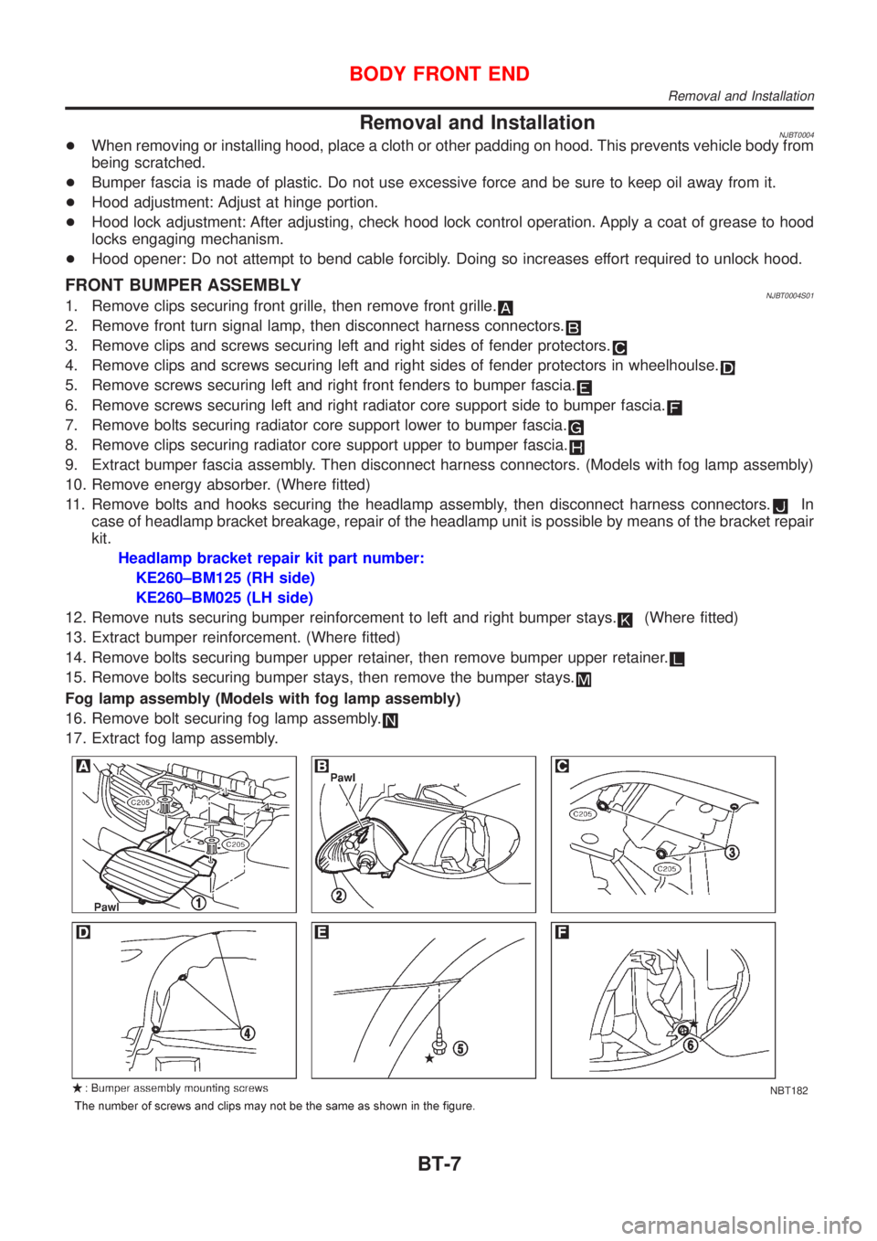
FRONT BUMPER ASSEMBLYNJBT0004S011. Remove clips securing front grille, then remove front grille.
2. Remove front turn signal lamp, then disconnect harness connectors.
3. Remove clips and screws securing left and right sides of fender protectors.
4. Remove clips and screws securing left and right sides of fender protectors in wheelhoulse.
5. Remove screws securing left and right front fenders to bumper fascia.
6. Remove screws securing left and right radiator core support side to bumper fascia.
7. Remove bolts securing radiator core support lower to bumper fascia.
8. Remove clips securing radiator core support upper to bumper fascia.
9. Extract bumper fascia assembly. Then disconnect harness connectors. (Models with fog lamp assembly)
10. Remove energy absorber. (Where fitted)
11. Remove bolts and hooks securing the headlamp assembly, then disconnect harness connectors.
In
case of headlamp bracket breakage, repair of the headlamp unit is possible by means of the bracket repair
kit.
Headlamp bracket repair kit part number:
KE260±BM125 (RH side)
KE260±BM025 (LH side)
12. Remove nuts securing bumper reinforcement to left and right bumper stays.
(Where fitted)
13. Extract bumper reinforcement. (Where fitted)
14. Remove bolts securing bumper upper retainer, then remove bumper upper retainer.
15. Remove bolts securing bumper stays, then remove the bumper stays.
Fog lamp assembly (Models with fog lamp assembly)
16. Remove bolt securing fog lamp assembly.
17. Extract fog lamp assembly.
NBT182
BODY FRONT END
Removal and Installation
BT-7
Page 2487 of 2493

Shock absorber (rear) ............................... SU-21
Side air bag ............................................... RS-33
Side trim .................................................... BT-31
Spare tire size ............................................ GI-43
Speedometer ............................................. EL-89
Spiral cable ............................................... RS-29
Spot lamp .................................................. EL-87
Spring (Wheelarch) height .......................... SU-6
Stabilizer bar (front) ................................... SU-11
Stall test (A/T) ............................................ AT-78
Standardized relay ....................................... EL-7
Start signal ...................................... EC-460, 693
Starter ....................................................... SC-16
Starting system ......................................... SC-13
Steering linkage ......................................... ST-15
Steering switch .......................................... EL-39
Steering wheel and column ....................... ST-10
Steering wheel play ..................................... ST-6
Steering wheel turning force ....................... ST-8
Stop lamp .................................................. EL-56
Striking rod (M/T) .......................... MT-32, 56, 94
Strut (front) .................................................. SU-9
Strut (rear) ................................................. SU-20
Sub-gear (M/T) ................................... MT-31, 55
Sunroof, electric ....................................... EL-165
Sunroof ...................................................... BT-60
Super lock ................................................ EL-196
Supplemental Restraint System ............... RS-20
Supplemental restraint system - Wiring
diagram .................................................. RS-46
Symbols and abbreviations ........................ GI-11
Symptom matrix chart ..................... EC-124, 541
Synchronizer (M/T) ....................... MT-31, 55, 93
System readiness test (SRT) code ........... EC-60
T
TCM circuit diagram ................................... AT-17
TCM inspection table ............................... AT-117
TP/SW - Wiring diagram ................. EC-323, 427
TPS - Wiring diagram ............................. EC-171
TURN - Wiring diagram ............................. EL-67
Tachometer ................................................ EL-89
Tail lamp .................................................... EL-53
Thermostat .......................................... LC-15, 40
Three way catalyst precautions ................... GI-6
Three way catalyst .................................. EC-299
Throttle position sensor (TPS) ................ EC-168
Throttle position sensor adjustment .......... EC-98
Throttle position switch ........... AT-139, 264, 333,
EC-321, 426
Throwout bearing - See Clutch release
bearing ............................................. CL-17, 20
Tie-rod ball joints ....................................... ST-19
Tie-rod ........................................................ ST-15
Tightening torque of standard bolts ........... GI-49
Timing chain ....................................... EM-22, 93
Tire size ...................................................... GI-43
Torque converter installation .................... AT-347Tow truck towing ........................................ GI-47
Transmission case (M/T) .............. MT-30, 54, 92
Tread-FR&RR (Dimensions) ...................... GI-43
Trim ............................................................ BT-31
Trouble diagnoses ...................................... GI-31
Trunk lid finisher ........................................ BT-45
Trunk lid opener - See Trunk lid ................ BT-10
Trunk lid trim .............................................. BT-45
Trunk lid ..................................................... BT-10
Trunk room lamp ....................................... EL-87
Trunk room trim ......................................... BT-45
Turn signal lamp ........................................ EL-65
Two trip detection logic ............................. EC-57
Two-pole lift ................................................ GI-46
U
Under body ................................................ BT-77
V
VSS - Wiring diagram ..................... EC-311, 593
Vacuum hose (brake system) ................... BR-22
Vacuum hose drawing (Engine control) .... EC-27
Vacuum pump ........................................... BR-23
Valve clearance ................................ EM-42, 132
Valve guide ....................................... EM-38, 123
Valve lifter ................................................. EM-41
Valve seat ......................................... EM-40, 125
Valve spring ...................................... EM-41, 127
Vehicle speed sensor (VSS) ........... EC-309, 593
Viscosity number (SAE) ............................ MA-21
Viscous coupling (FF M/T) ........................ MT-93
W
WARN - Wiring diagram .......................... EL-108
WIP/R - Wiring diagram .......................... EL-129
WIPER - Wiring diagram ......................... EL-125
Warning chime ......................................... EL-113
Warning lamps ......................................... EL-107
Washer, front ........................................... EL-123
Water pump ......................................... LC-14, 38
Water temperature gauge .......................... EL-89
Weatherstrip - See Exterior ....................... BT-47
Wheel alignment (rear) ............................. SU-18
Wheel bearing (front) .................................. AX-3
Wheel bearing (rear) ................................. AX-23
Wheel hub (front) ........................................ AX-5
Wheel hub (rear) ....................................... AX-24
Wheel sensors (ABS) ............................... BR-88
Wheelarch height ........................................ SU-6
Wheelbase (Dimensions) ........................... GI-43
Wide open & closed throttle position
switch ................................................... EC-168
Width (Dimensions) .................................... GI-43
Window, rear .............................................. BT-68
ALPHABETICAL INDEX
IDX-7