Page 702 of 2493
5 CHECK OVERALL FUNCTION-II
Without CONSULT-II
1. Warm up engine to normal operating temperature.
2. Rev engine from idle up to about 3,000 rpm two to three times.
3. Make sure the voltage between ECM terminal 72 and ground is lower than the voltage measured in test No. 4 by 1.0V
or more.
SEF755Z
OK or NG
OK©INSPECTION END
NG©GO TO 6.
6 CHECK EGR TEMPERATURE SENSOR POWER SUPPLY
1. Turn ignition switch ªOFFº.
2. Disconnect EGR temperature sensor harness connector.
SEF127X
3. Turn ignition switch ªONº.
4. Check voltage between terminal 1 and ground with CONSULT-II or tester.
SEF896X
OK or NG
OK©GO TO 7.
NG©Repair harness or connectors.
EGR VOLUME CONTROL SYSTEM (WHERE FITTED)QG
Diagnostic Procedure (Cont'd)
EC-406
Page 703 of 2493
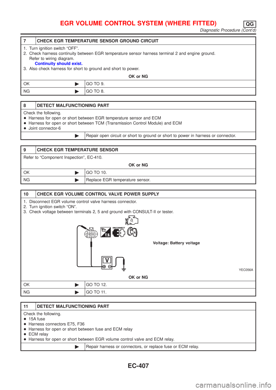
7 CHECK EGR TEMPERATURE SENSOR GROUND CIRCUIT
1. Turn ignition switch ªOFFº.
2. Check harness continuity between EGR temperature sensor harness terminal 2 and engine ground.
Refer to wiring diagram.
Continuity should exist.
3. Also check harness for short to ground and short to power.
OK or NG
OK©GO TO 9.
NG©GO TO 8.
8 DETECT MALFUNCTIONING PART
Check the following.
+Harness for open or short between EGR temperature sensor and ECM
+Harness for open or short between TCM (Transmission Control Module) and ECM
+Joint connector-6
©Repair open circuit or short to ground or short to power in harness or connector.
9 CHECK EGR TEMPERATURE SENSOR
Refer to ªComponent Inspectionº, EC-410.
OK or NG
OK©GO TO 10.
NG©Replace EGR temperature sensor.
10 CHECK EGR VOLUME CONTROL VALVE POWER SUPPLY
1. Disconnect EGR volume control valve harness connector.
2. Turn ignition switch ªONº.
3. Check voltage between terminals 2, 5 and ground with CONSULT-II or tester.
YEC056A
OK or NG
OK©GO TO 12.
NG©GO TO 11.
11 DETECT MALFUNCTIONING PART
Check the following.
+15A fuse
+Harness connectors E75, F36
+Harness for open or short between fuse and ECM relay
+ECM relay
+Harness for open or short between EGR volume control valve and ECM relay.
©Repair harness or connectors, or replace fuse or ECM relay.
EGR VOLUME CONTROL SYSTEM (WHERE FITTED)QG
Diagnostic Procedure (Cont'd)
EC-407
Page 710 of 2493
Diagnostic ProcedureNJEC1756
1 INSPECTION START
Do you have CONSULT-II?
YesorNo
Ye s©GO TO 2.
No©GO TO 3.
2 CHECK EVAP CANISTER PURGE VOLUME CONTROL SOLENOID VALVE CONTROL FUNCTION
With CONSULT-II
1. Turn ignition switch ªOFFº.
2. Disconnect the EVAP purge hose connected to the EVAP canister purge volume control solenoid valve at the EVAP
canister.
3. Turn ignition switch ªONº and select ªPURG VOL CONT/Vº in ªACTIVE TESTº mode with CONSULT-II.
4. Start engine and let it idle.
5. Change the valve opening percentage touching ªQuº and ªQdº and check for vacuum existence under the following
conditions.
SEC582C
OK or NG
OK©GO TO 4.
NG©GO TO 5.
EVAP CANISTER PURGE VOLUME CONTROL SOLENOID VALVEQG
Diagnostic Procedure
EC-414
Page 711 of 2493
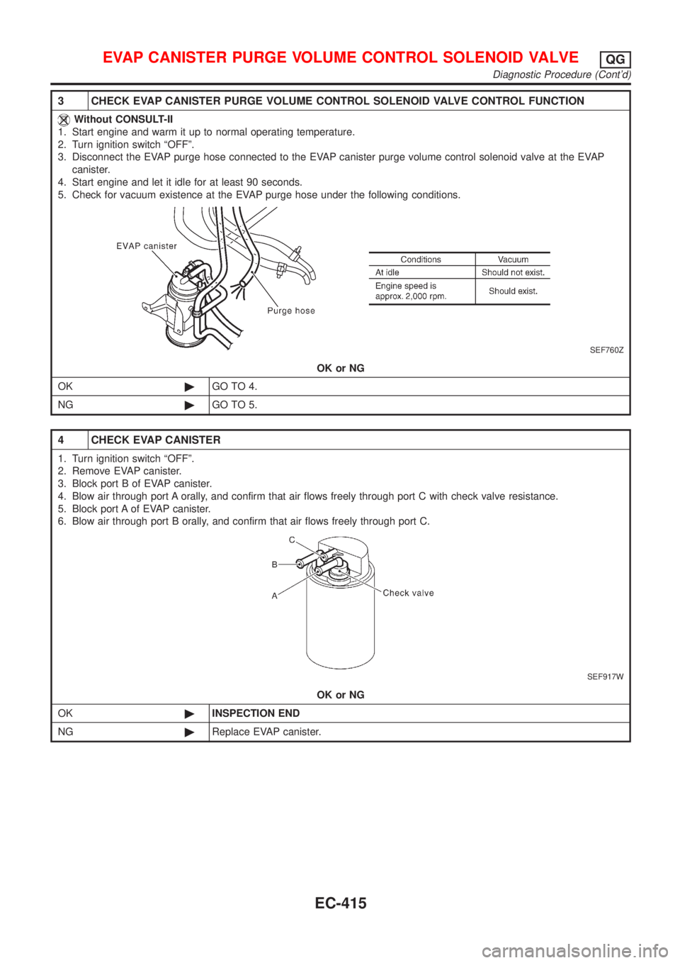
3 CHECK EVAP CANISTER PURGE VOLUME CONTROL SOLENOID VALVE CONTROL FUNCTION
Without CONSULT-II
1. Start engine and warm it up to normal operating temperature.
2. Turn ignition switch ªOFFº.
3. Disconnect the EVAP purge hose connected to the EVAP canister purge volume control solenoid valve at the EVAP
canister.
4. Start engine and let it idle for at least 90 seconds.
5. Check for vacuum existence at the EVAP purge hose under the following conditions.
SEF760Z
OK or NG
OK©GO TO 4.
NG©GO TO 5.
4 CHECK EVAP CANISTER
1. Turn ignition switch ªOFFº.
2. Remove EVAP canister.
3. Block port B of EVAP canister.
4. Blow air through port A orally, and confirm that air flows freely through port C with check valve resistance.
5. Block port A of EVAP canister.
6. Blow air through port B orally, and confirm that air flows freely through port C.
SEF917W
OK or NG
OK©INSPECTION END
NG©Replace EVAP canister.
EVAP CANISTER PURGE VOLUME CONTROL SOLENOID VALVEQG
Diagnostic Procedure (Cont'd)
EC-415
Page 712 of 2493
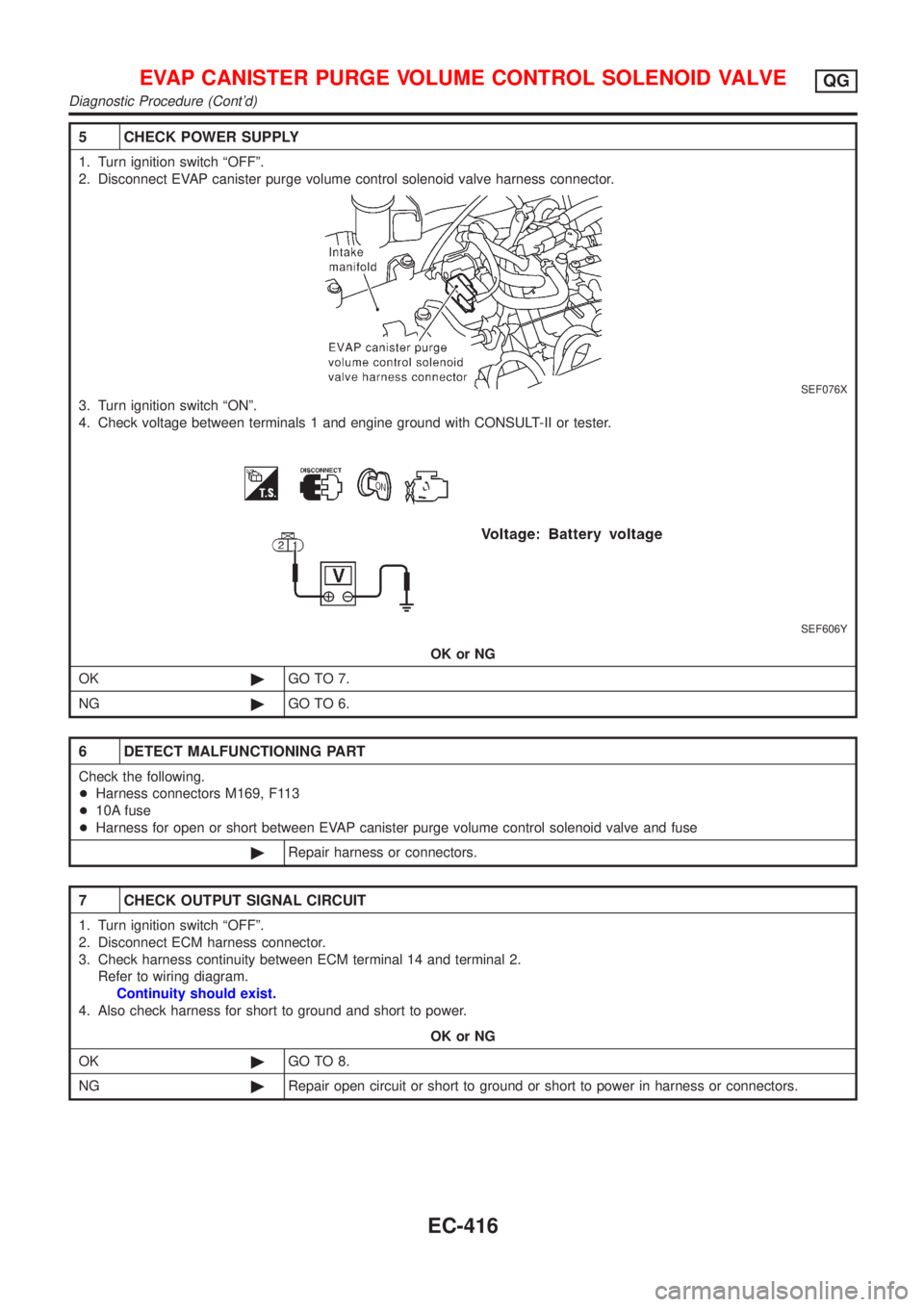
5 CHECK POWER SUPPLY
1. Turn ignition switch ªOFFº.
2. Disconnect EVAP canister purge volume control solenoid valve harness connector.
SEF076X
3. Turn ignition switch ªONº.
4. Check voltage between terminals 1 and engine ground with CONSULT-II or tester.
SEF606Y
OK or NG
OK©GO TO 7.
NG©GO TO 6.
6 DETECT MALFUNCTIONING PART
Check the following.
+Harness connectors M169, F113
+10A fuse
+Harness for open or short between EVAP canister purge volume control solenoid valve and fuse
©Repair harness or connectors.
7 CHECK OUTPUT SIGNAL CIRCUIT
1. Turn ignition switch ªOFFº.
2. Disconnect ECM harness connector.
3. Check harness continuity between ECM terminal 14 and terminal 2.
Refer to wiring diagram.
Continuity should exist.
4. Also check harness for short to ground and short to power.
OK or NG
OK©GO TO 8.
NG©Repair open circuit or short to ground or short to power in harness or connectors.
EVAP CANISTER PURGE VOLUME CONTROL SOLENOID VALVEQG
Diagnostic Procedure (Cont'd)
EC-416
Page 713 of 2493
8 CHECK EVAP CANISTER PURGE VOLUME CONTROL SOLENOID VALVE
Refer to ªComponent Inspectionº, EC-417.
OK or NG
OK©GO TO 9.
NG©Replace EVAP canister purge volume control solenoid valve.
9 CHECK INTERMITTENT INCIDENT
Perform ªTROUBLE DIAGNOSIS FOR INTERMITTENT INCIDENTº, EC-144.
©INSPECTION END
SEF801Y
SEF661U
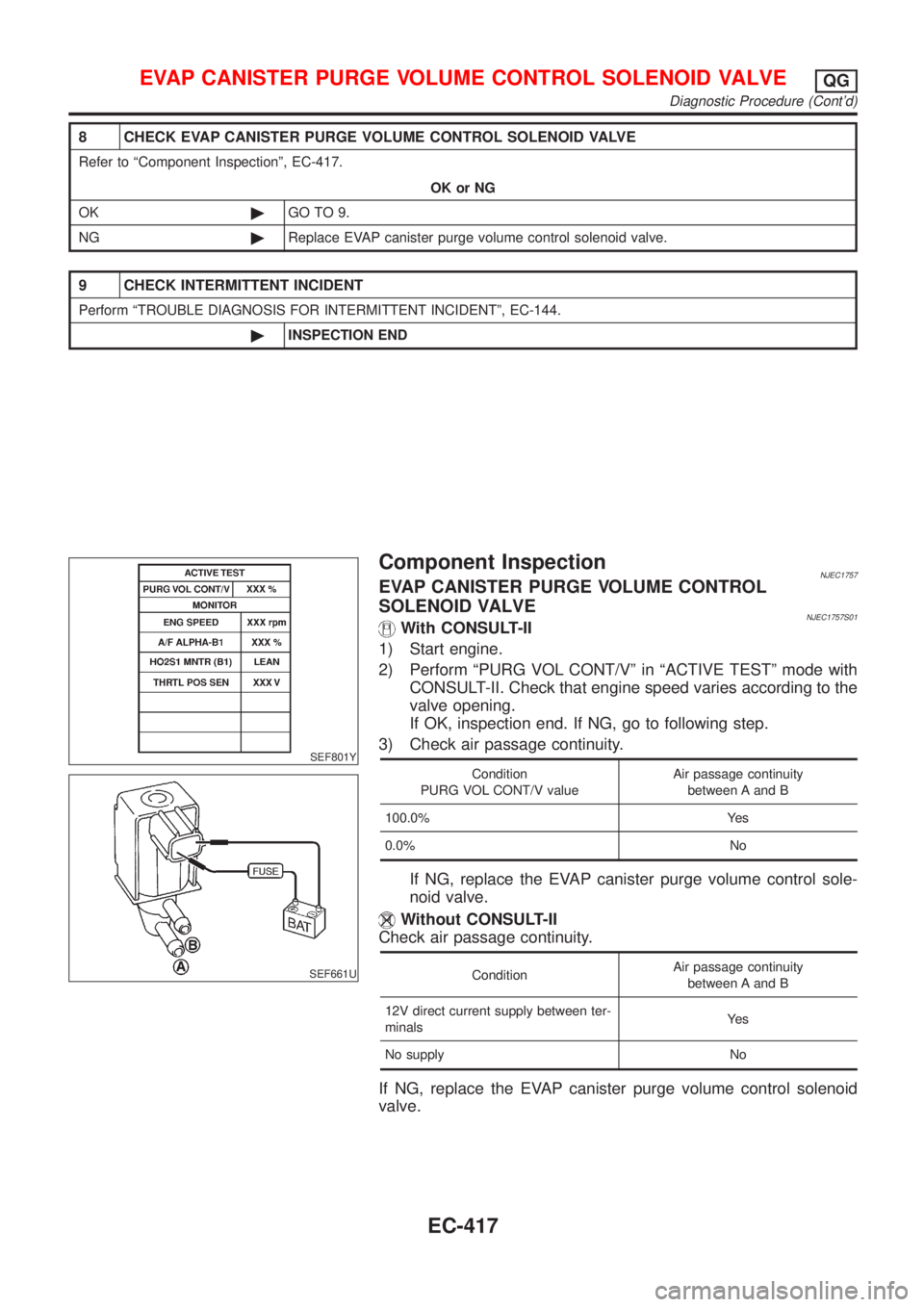
Component InspectionNJEC1757EVAP CANISTER PURGE VOLUME CONTROL
SOLENOID VALVE
NJEC1757S01With CONSULT-II
1) Start engine.
2) Perform ªPURG VOL CONT/Vº in ªACTIVE TESTº mode with
CONSULT-II. Check that engine speed varies according to the
valve opening.
If OK, inspection end. If NG, go to following step.
3) Check air passage continuity.
Condition
PURG VOL CONT/V valueAir passage continuity
between A and B
100.0% Yes
0.0% No
If NG, replace the EVAP canister purge volume control sole-
noid valve.
Without CONSULT-II
Check air passage continuity.
ConditionAir passage continuity
between A and B
12V direct current supply between ter-
minalsYe s
No supply No
If NG, replace the EVAP canister purge volume control solenoid
valve.
EVAP CANISTER PURGE VOLUME CONTROL SOLENOID VALVEQG
Diagnostic Procedure (Cont'd)
EC-417
Page 718 of 2493
3 DETECT MALFUNCTIONING PART
Check the following.
+15A fuse
+Harness connectors E75, F36 (If so equipped)
+Harness for open or short between fuse and ECM relay
+ECM relay
+Harness for open or short between IACV-AAC and ECM relay.
©Repair harness or connectors, or replace fuse or ECM relay.
4 CHECK OUTPUT SIGNAL CIRCUIT
1. Turn ignition switch ªOFFº.
2. Disconnect ECM harness connector.
3. Check harness continuity between
ECM terminal 6 and IACV-AAC valve terminal 1,
ECM terminal 7 and IACV-AAC valve terminal 4,
ECM terminal 15 and IACV-AAC valve terminal 3,
ECM terminal 16 and IACV-AAC valve terminal 6.
Refer to wiring diagram.
Continuity should exist.
4. Also check harness for short to ground and short to power.
OK or NG
OK©GO TO 5.
NG©Repair open circuit or short to ground or short to power in harness or connectors.
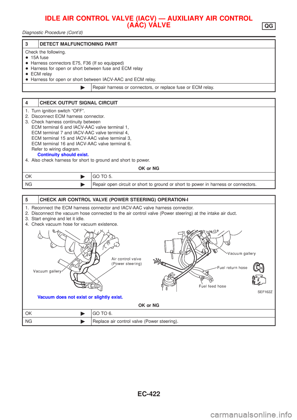
5 CHECK AIR CONTROL VALVE (POWER STEERING) OPERATION-I
1. Reconnect the ECM harness connector and IACV-AAC valve harness connector.
2. Disconnect the vacuum hose connected to the air control valve (Power steering) at the intake air duct.
3. Start engine and let it idle.
4. Check vacuum hose for vacuum existence.
SEF162Z
Vacuum does not exist or slightly exist.
OK or NG
OK©GO TO 6.
NG©Replace air control valve (Power steering).
IDLE AIR CONTROL VALVE (IACV) Ð AUXILIARY AIR CONTROL
(AAC) VALVE
QG
Diagnostic Procedure (Cont'd)
EC-422
Page 719 of 2493
6 CHECK AIR CONTROL VALVE (POWER STEERING) OPERATION-II
Check the vacuum hose for vacuum existence when steering wheel is turned.
SEF162Z
Vacuum should exist.
OK or NG
OK©GO TO 9.
NG©GO TO 7.
7 CHECK VACUUM PORT
1. Stop engine.
2. Disconnect the vacuum hose connected to the air control valve (Power steering) at the vacuum port.
3. Blow air into vacuum port.
4. Check that air flows freely.
SEF924Y
OK or NG
OK©GO TO 8.
NG©Repair or clean vacuum port.
IDLE AIR CONTROL VALVE (IACV) Ð AUXILIARY AIR CONTROL
(AAC) VALVE
QG
Diagnostic Procedure (Cont'd)
EC-423