2001 NISSAN ALMERA N16 check engine
[x] Cancel search: check enginePage 2367 of 2493
DIAGNOSTIC PROCEDURE 7=NJEL0411S11Self-diagnostic results:
ªLOCK MODEº displayed on CONSULT-II screen
1 CONFIRM SELF-DIAGNOSTIC RESULTS
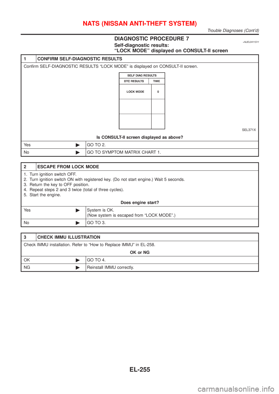
Confirm SELF-DIAGNOSTIC RESULTS ªLOCK MODEº is displayed on CONSULT-II screen.
SEL371X
Is CONSULT-II screen displayed as above?
Ye s©GO TO 2.
No©GO TO SYMPTOM MATRIX CHART 1.
2 ESCAPE FROM LOCK MODE
1. Turn ignition switch OFF.
2. Turn ignition switch ON with registered key. (Do not start engine.) Wait 5 seconds.
3. Return the key to OFF position.
4. Repeat steps 2 and 3 twice (total of three cycles).
5. Start the engine.
Does engine start?
Ye s©System is OK.
(Now system is escaped from ªLOCK MODEº.)
No©GO TO 3.
3 CHECK IMMU ILLUSTRATION
Check IMMU installation. Refer to ªHow to Replace IMMUº in EL-258.
OK or NG
OK©GO TO 4.
NG©Reinstall IMMU correctly.
NATS (NISSAN ANTI-THEFT SYSTEM)
Trouble Diagnoses (Cont'd)
EL-255
Page 2390 of 2493
Self-diagnosis ModeNJEL0519APPLICATION ITEMSNJEL0519S01
Mode DescriptionReference
page
Self DiagnosisSelf-diagnosis for Navigation, Display and GPS Antenna
connection.EL-279
Confirmation/
adjustmentDiagnose the DisplayColor and gray gradation of display can be checked in
this mode.EL-287
Diagnosis for Signals from the CarSeveral input signals to NAVI control unit, can be moni-
tored in this mode.EL-285
NavigationCheck the map CD-
ROM versionThe version (parts number) of inserted CD-ROM can be
checked in this model.EL-286
Error historyDiagnosis results previously stored in the memory
(before turning ignition switch ON) are displayed in this
mode. Time and location when/where the errors
occurred are also displayed.EL-281
Longitude & LatitudeDisplay the map. Use the joystick to adjust position. Lon-
gitude and latitude will be displayed.EL-288
Adjust the AngleTurning angle of the vehicle on the display can be
adjusted in this mode.EL-289
Speed CalibrationUnder ordinary conditions, the navigation system dis-
tance measuring function will automatically compensate
for minute decreases in wheel and tire diameter caused
by tire wear or low pressure. Speed calibration immedi-
ately restores system accuracy in cases such as when
distance calibration is needed because of the use of tire
chains in inclement weather.EL-290
Initialize LocationThis mode is for initializing the current location. Use
when the vehicle is transported a long distance by a
trailer, etc.EL-291
MODEMAP
SEL617X
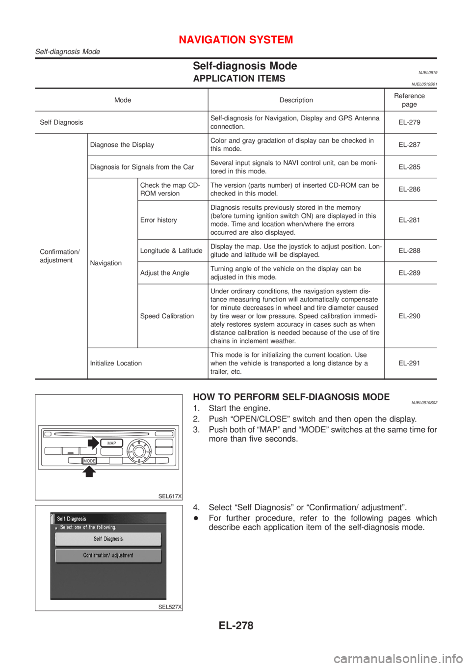
HOW TO PERFORM SELF-DIAGNOSIS MODENJEL0519S021. Start the engine.
2. Push ªOPEN/CLOSEº switch and then open the display.
3. Push both of ªMAPº and ªMODEº switches at the same time for
more than five seconds.
SEL527X
4. Select ªSelf Diagnosisº or ªConfirmation/ adjustmentº.
+For further procedure, refer to the following pages which
describe each application item of the self-diagnosis mode.
NAVIGATION SYSTEM
Self-diagnosis Mode
EL-278
Page 2397 of 2493
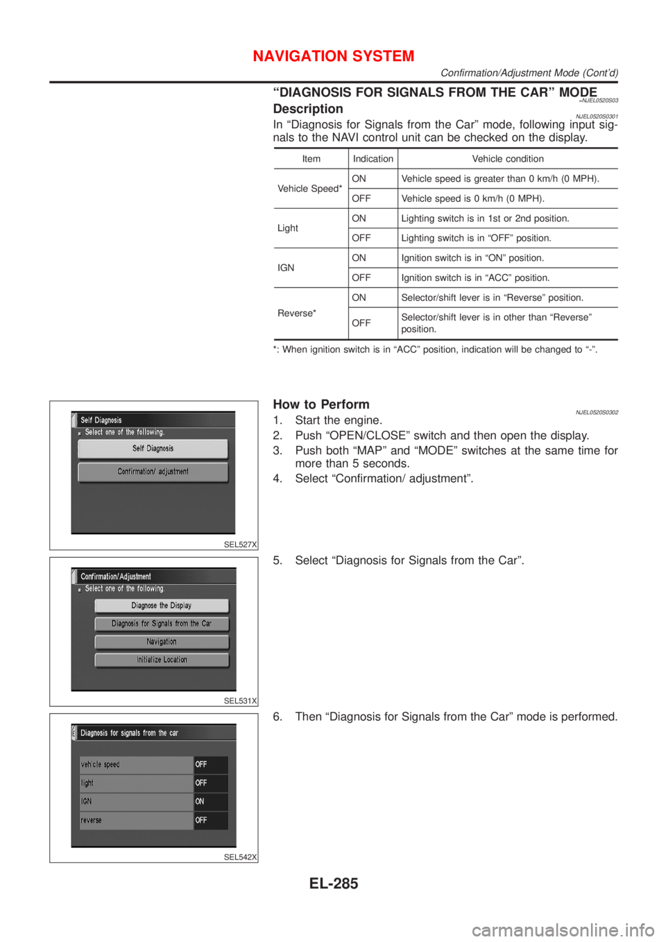
ªDIAGNOSIS FOR SIGNALS FROM THE CARº MODE=NJEL0520S03DescriptionNJEL0520S0301In ªDiagnosis for Signals from the Carº mode, following input sig-
nals to the NAVI control unit can be checked on the display.
Item Indication Vehicle condition
Vehicle Speed*ON Vehicle speed is greater than 0 km/h (0 MPH).
OFF Vehicle speed is 0 km/h (0 MPH).
LightON Lighting switch is in 1st or 2nd position.
OFF Lighting switch is in ªOFFº position.
IGNON Ignition switch is in ªONº position.
OFF Ignition switch is in ªACCº position.
Reverse*ON Selector/shift lever is in ªReverseº position.
OFFSelector/shift lever is in other than ªReverseº
position.
*: When ignition switch is in ªACCº position, indication will be changed to ª-º.
SEL527X
How to PerformNJEL0520S03021. Start the engine.
2. Push ªOPEN/CLOSEº switch and then open the display.
3. Push both ªMAPº and ªMODEº switches at the same time for
more than 5 seconds.
4. Select ªConfirmation/ adjustmentº.
SEL531X
5. Select ªDiagnosis for Signals from the Carº.
SEL542X
6. Then ªDiagnosis for Signals from the Carº mode is performed.
NAVIGATION SYSTEM
Confirmation/Adjustment Mode (Cont'd)
EL-285
Page 2398 of 2493
SEL527X
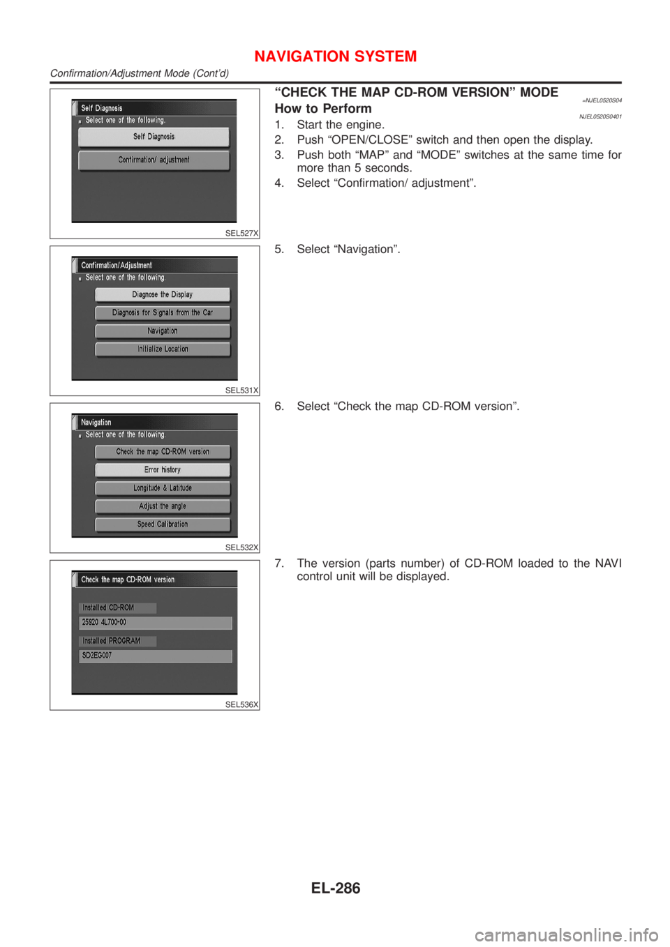
ªCHECK THE MAP CD-ROM VERSIONº MODE=NJEL0520S04How to PerformNJEL0520S04011. Start the engine.
2. Push ªOPEN/CLOSEº switch and then open the display.
3. Push both ªMAPº and ªMODEº switches at the same time for
more than 5 seconds.
4. Select ªConfirmation/ adjustmentº.
SEL531X
5. Select ªNavigationº.
SEL532X
6. Select ªCheck the map CD-ROM versionº.
SEL536X
7. The version (parts number) of CD-ROM loaded to the NAVI
control unit will be displayed.
NAVIGATION SYSTEM
Confirmation/Adjustment Mode (Cont'd)
EL-286
Page 2399 of 2493
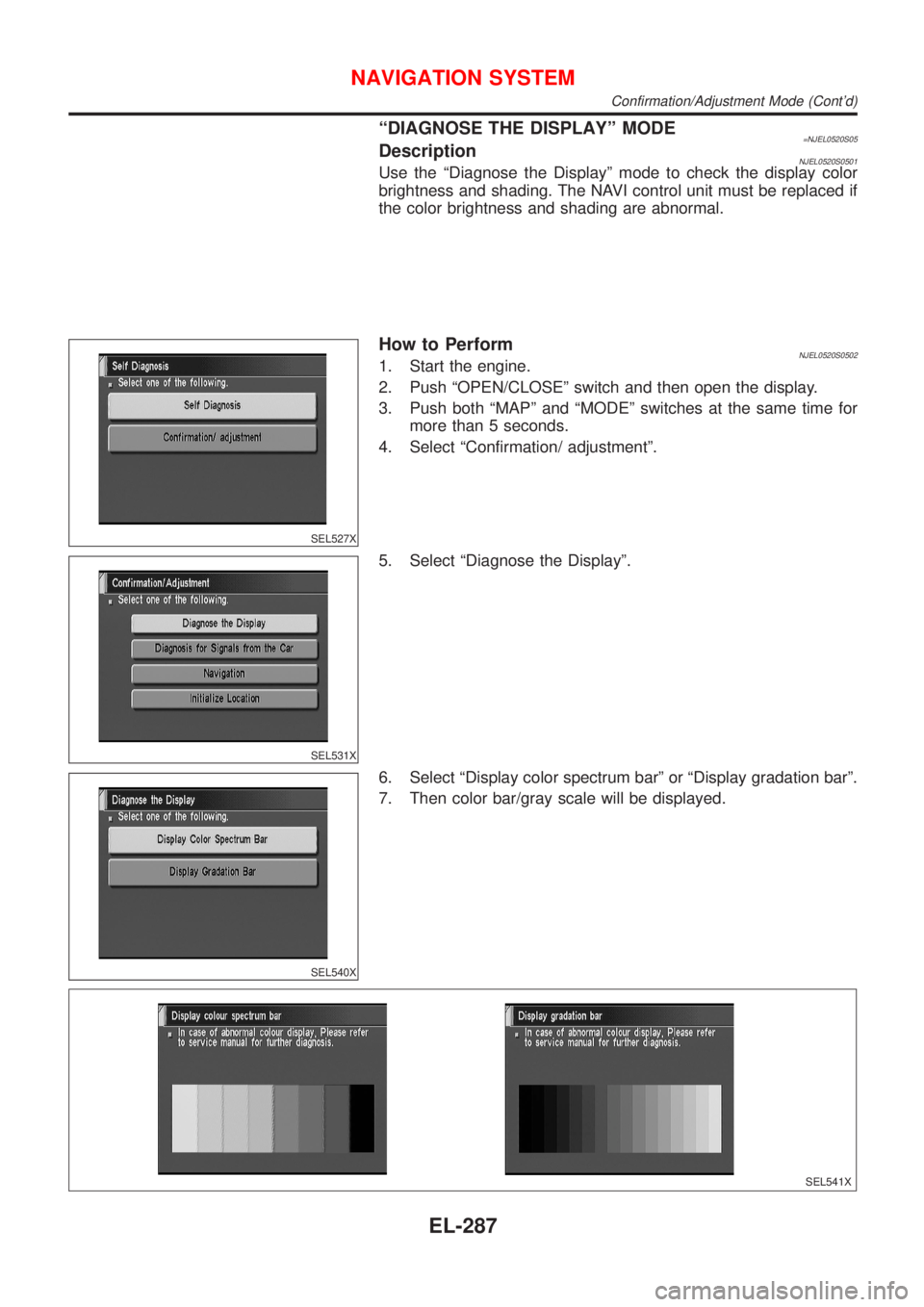
ªDIAGNOSE THE DISPLAYº MODE=NJEL0520S05DescriptionNJEL0520S0501Use the ªDiagnose the Displayº mode to check the display color
brightness and shading. The NAVI control unit must be replaced if
the color brightness and shading are abnormal.
SEL527X
How to PerformNJEL0520S05021. Start the engine.
2. Push ªOPEN/CLOSEº switch and then open the display.
3. Push both ªMAPº and ªMODEº switches at the same time for
more than 5 seconds.
4. Select ªConfirmation/ adjustmentº.
SEL531X
5. Select ªDiagnose the Displayº.
SEL540X
6. Select ªDisplay color spectrum barº or ªDisplay gradation barº.
7. Then color bar/gray scale will be displayed.
SEL541X
NAVIGATION SYSTEM
Confirmation/Adjustment Mode (Cont'd)
EL-287
Page 2401 of 2493
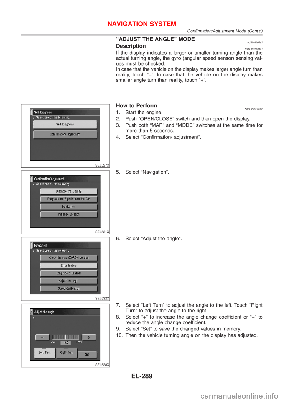
ªADJUST THE ANGLEº MODENJEL0520S07DescriptionNJEL0520S0701If the display indicates a larger or smaller turning angle than the
actual turning angle, the gyro (angular speed sensor) sensing val-
ues must be checked.
In case that the vehicle on the display makes larger angle turn than
reality, touch ªþº. In case that the vehicle on the display makes
smaller angle turn than reality, touch ª+º.
SEL527X
How to PerformNJEL0520S07021. Start the engine.
2. Push ªOPEN/CLOSEº switch and then open the display.
3. Push both ªMAPº and ªMODEº switches at the same time for
more than 5 seconds.
4. Select ªConfirmation/ adjustmentº.
SEL531X
5. Select ªNavigationº.
SEL532X
6. Select ªAdjust the angleº.
SEL538X
7. Select ªLeft Turnº to adjust the angle to the left. Touch ªRight
Turnº to adjust the angle to the right.
8. Select ª+º to increase the angle change coefficient or ªþº to
reduce the angle change coefficient.
9. Select ªSetº to save the changed values in memory.
10. Then the vehicle turning angle on the display has adjusted.
NAVIGATION SYSTEM
Confirmation/Adjustment Mode (Cont'd)
EL-289
Page 2424 of 2493
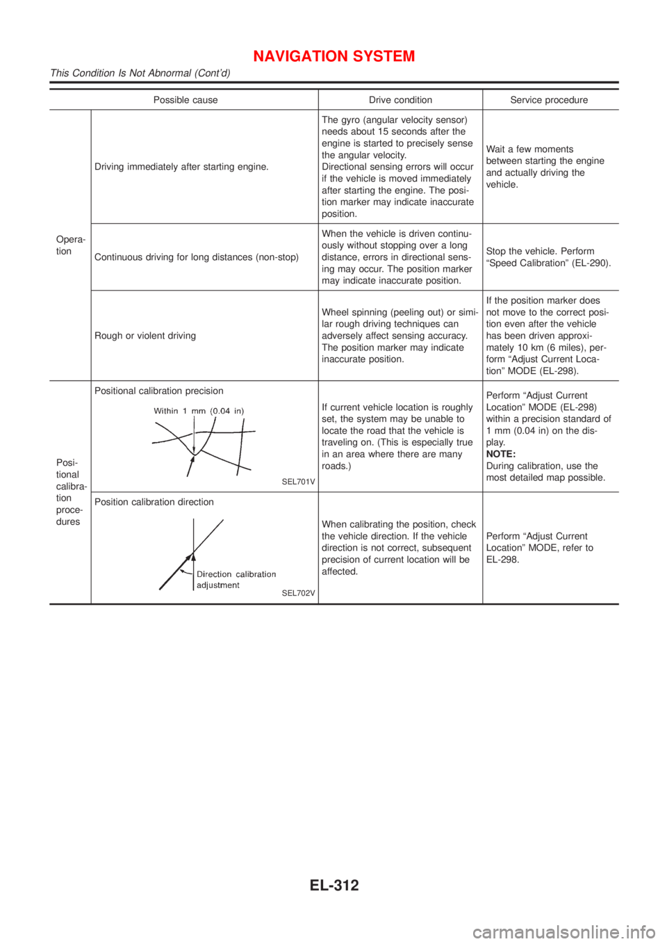
Possible cause Drive condition Service procedure
Opera-
tionDriving immediately after starting engine.The gyro (angular velocity sensor)
needs about 15 seconds after the
engine is started to precisely sense
the angular velocity.
Directional sensing errors will occur
if the vehicle is moved immediately
after starting the engine. The posi-
tion marker may indicate inaccurate
position.Wait a few moments
between starting the engine
and actually driving the
vehicle.
Continuous driving for long distances (non-stop)When the vehicle is driven continu-
ously without stopping over a long
distance, errors in directional sens-
ing may occur. The position marker
may indicate inaccurate position.Stop the vehicle. Perform
ªSpeed Calibrationº (EL-290).
Rough or violent drivingWheel spinning (peeling out) or simi-
lar rough driving techniques can
adversely affect sensing accuracy.
The position marker may indicate
inaccurate position.If the position marker does
not move to the correct posi-
tion even after the vehicle
has been driven approxi-
mately 10 km (6 miles), per-
form ªAdjust Current Loca-
tionº MODE (EL-298).
Posi-
tional
calibra-
tion
proce-
duresPositional calibration precision
SEL701V
If current vehicle location is roughly
set, the system may be unable to
locate the road that the vehicle is
traveling on. (This is especially true
in an area where there are many
roads.)Perform ªAdjust Current
Locationº MODE (EL-298)
within a precision standard of
1 mm (0.04 in) on the dis-
play.
NOTE:
During calibration, use the
most detailed map possible.
Position calibration direction
SEL702V
When calibrating the position, check
the vehicle direction. If the vehicle
direction is not correct, subsequent
precision of current location will be
affected.Perform ªAdjust Current
Locationº MODE, refer to
EL-298.
NAVIGATION SYSTEM
This Condition Is Not Abnormal (Cont'd)
EL-312
Page 2484 of 2493

Engine control module (ECM) ....... EC-327, 554,
604, 664, 666, 670, 672
Engine control system diagram and
chart .............................................. EC-26, 503
Engine coolant temperature sensor
(ECTS) ........................................ EC-163, 572
Engine fail-safe system ........................... EC-123
Engine oil precautions .................................. GI-7
Engine outer component parts ................. EM-11
Engine removal ................................ EM-49, 136
Engine room - See Engine
compartment .......................................... BT-75
Engine serial number ................................. GI-41
Evaporative emission (EVAP)
system ................................................... EC-33
Exhaust gas recirculation (EGR)
valve .................................... EC-285, 353, 400
Exhaust system ................................... FE-11, 27
Exterior ...................................................... BT-47
F
F/PUMP - Wiring diagram ....................... EC-466
FR02 - Wiring diagram ... EC-179, 198, 205, 374
FR02/H - Wiring diagram ................ EC-211, 380
FUEL - Wiring diagram ................... EC-250, 257
Fan switch ................................................. HA-60
Final drive (FF A/T) .................................. AT-424
Final drive (FF M/T) .............. MT-43, 77, 93, 107
Finisher, interior - See Trim ....................... BT-31
Finisher, trunk lid ....................................... BT-45
Floor trim ................................................... BT-31
Fluid temperature sensor (A/T) ................ AT-192
Fluids ........................................................ MA-20
Flywheel (clutch) ....................................... CL-22
Flywheel runout ................................ EM-60, 153
Fog lamp, front, removal and
installation ................................................ BT-7
Fog lamp, front .......................................... EL-60
Fork rod (M/T) .............................. MT-32, 56, 94
Forward clutch ......................................... AT-399
Freeze frame data .............................. EC-59, 70
Front axle .................................................... AX-2
Front bumper ............................................... BT-7
Front combination lamp removal and
installation ................................................ BT-7
Front disc brake ........................................ BR-27
Front door .................................................. BT-16
Front fog lamp removal and
installation ................................................ BT-7
Front fog lamp ........................................... EL-60
Front heated oxygen sensor (HO2S)
heater .......................................... EC-209, 379
Front heated oxygen sensor (HO2S) ..... EC-176,
183, 189, 195, 203, 373
Front seat belt ............................................. RS-5
Front seat .................................................. BT-56
Front suspension ........................................ SU-2
Front washer ............................................ EL-123Front wiper ............................................... EL-123
Fuel cut control (at no load & high
engine speed) ............................... EC-33, 507
Fuel gauge ................................................. EL-89
Fuel injection system .............. EC-248, 255, 505
Fuel injector ............................................ EC-446
Fuel precautions ........................................... GI-8
Fuel pressure check ................................. EC-38
Fuel pressure regulator ............................. EC-39
Fuel pressure release ............................... EC-38
Fuel pump relay ...................................... EC-464
Fuel pump ............................................... EC-464
Fuel system ........................................... FE-5, 16
Fuel tank vacuum relief valve ................... EC-34
Fuse block ............................................... EL-369
Fuse ........................................................... EL-22
Fusible link ................................................. EL-22
G
GLOW - Wiring diagram ......................... EC-677
Garage jack and safety stand .................... GI-45
Gauges ...................................................... EL-89
Gear components (M/T) ............... MT-31, 55, 93
Generator - See Alternator ....................... SC-27
Generic scan tool (GST) ........................... EC-92
Glass .......................................................... BT-17
Glow plug ................................................ EC-677
Glow relay ............................................... EC-677
Grease ...................................................... MA-20
Ground distribution .................................... EL-23
H
H/LAMP - Wiring diagram .......................... EL-40
HEATER - Wiring diagram ........................ HA-24
HFC134a (R134a) system
recaution .................................................. HA-2
HFC134a (R134a) system service
procedure .............................................. HA-84
HFC134a (R134a) system service
tools ....................................................... HA-11
HFC134a system service equipment
precaution ................................................ HA-6
HORN - Wiring diagram .......................... EL-135
HSEAT - Wiring diagram ......................... EL-163
Harness connector ...................................... EL-5
Harness layout ......................................... EL-324
Hazard warning lamp ................................ EL-65
Headlamp removal and installation ............. BT-7
Headlamp washer .................................... EL-133
Headlamp .................................................. EL-40
Headlining - See Roof trim ........................ BT-43
Heated oxygen sensor (HO2S)
(front) .......... EC-176, 183, 189, 195, 203, 373
Heated oxygen sensor (HO2S) heater
(front) ........................................... EC-209, 379
ALPHABETICAL INDEX
IDX-4