2001 NISSAN ALMERA N16 check engine
[x] Cancel search: check enginePage 2077 of 2493
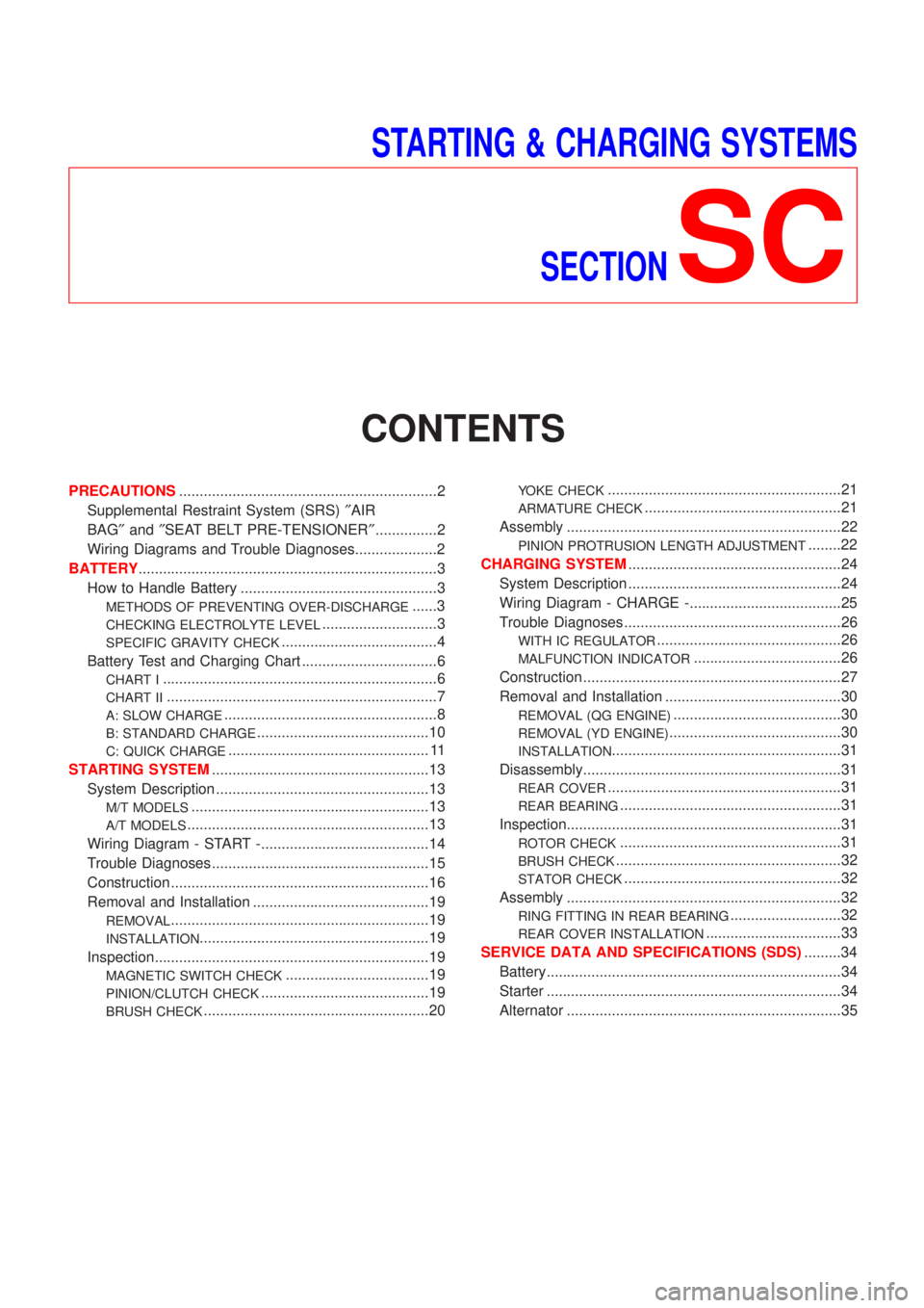
STARTING & CHARGING SYSTEMS
SECTION
SC
CONTENTS
PRECAUTIONS...............................................................2
Supplemental Restraint System (SRS)²AIR
BAG²and²SEAT BELT PRE-TENSIONER²...............2
Wiring Diagrams and Trouble Diagnoses....................2
BATTERY.........................................................................3
How to Handle Battery ................................................3
METHODS OF PREVENTING OVER-DISCHARGE......3
CHECKING ELECTROLYTE LEVEL............................3
SPECIFIC GRAVITY CHECK......................................4
Battery Test and Charging Chart .................................6
CHART I...................................................................6
CHART II..................................................................7
A: SLOW CHARGE....................................................8
B: STANDARD CHARGE..........................................10
C: QUICK CHARGE................................................. 11
STARTING SYSTEM.....................................................13
System Description ....................................................13
M/T MODELS..........................................................13
A/T MODELS...........................................................13
Wiring Diagram - START -.........................................14
Trouble Diagnoses.....................................................15
Construction ...............................................................16
Removal and Installation ...........................................19
REMOVAL...............................................................19
INSTALLATION........................................................19
Inspection...................................................................19
MAGNETIC SWITCH CHECK...................................19
PINION/CLUTCH CHECK.........................................19
BRUSH CHECK.......................................................20
YOKE CHECK.........................................................21
ARMATURE CHECK................................................21
Assembly ...................................................................22
PINION PROTRUSION LENGTH ADJUSTMENT........22
CHARGING SYSTEM....................................................24
System Description ....................................................24
Wiring Diagram - CHARGE -.....................................25
Trouble Diagnoses.....................................................26
WITH IC REGULATOR.............................................26
MALFUNCTION INDICATOR....................................26
Construction ...............................................................27
Removal and Installation ...........................................30
REMOVAL (QG ENGINE).........................................30
REMOVAL (YD ENGINE)..........................................30
INSTALLATION........................................................31
Disassembly...............................................................31
REAR COVER.........................................................31
REAR BEARING......................................................31
Inspection...................................................................31
ROTOR CHECK......................................................31
BRUSH CHECK.......................................................32
STATOR CHECK.....................................................32
Assembly ...................................................................32
RING FITTING IN REAR BEARING...........................32
REAR COVER INSTALLATION.................................33
SERVICE DATA AND SPECIFICATIONS (SDS).........34
Battery........................................................................34
Starter ........................................................................34
Alternator ...................................................................35
Page 2079 of 2493
How to Handle BatteryNJSC0003CAUTION:
If it becomes necessary to start the engine with a booster
battery and jumper cables,
1) Use a 12-volt booster battery.
2) After connecting battery cables, ensure that they are
tightly clamped to battery terminals for good contact.
3) Never add distilled water through the hole used to check
specific gravity.
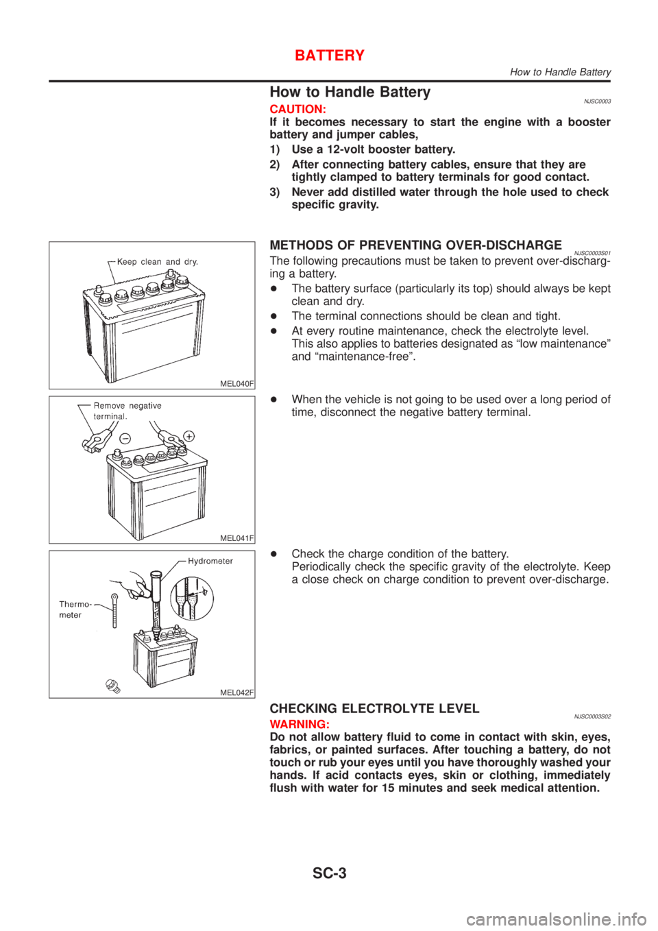
MEL040F
METHODS OF PREVENTING OVER-DISCHARGENJSC0003S01The following precautions must be taken to prevent over-discharg-
ing a battery.
+The battery surface (particularly its top) should always be kept
clean and dry.
+The terminal connections should be clean and tight.
+At every routine maintenance, check the electrolyte level.
This also applies to batteries designated as ªlow maintenanceº
and ªmaintenance-freeº.
MEL041F
+When the vehicle is not going to be used over a long period of
time, disconnect the negative battery terminal.
MEL042F
+Check the charge condition of the battery.
Periodically check the specific gravity of the electrolyte. Keep
a close check on charge condition to prevent over-discharge.
CHECKING ELECTROLYTE LEVELNJSC0003S02WARNING:
Do not allow battery fluid to come in contact with skin, eyes,
fabrics, or painted surfaces. After touching a battery, do not
touch or rub your eyes until you have thoroughly washed your
hands. If acid contacts eyes, skin or clothing, immediately
flush with water for 15 minutes and seek medical attention.
BATTERY
How to Handle Battery
SC-3
Page 2098 of 2493
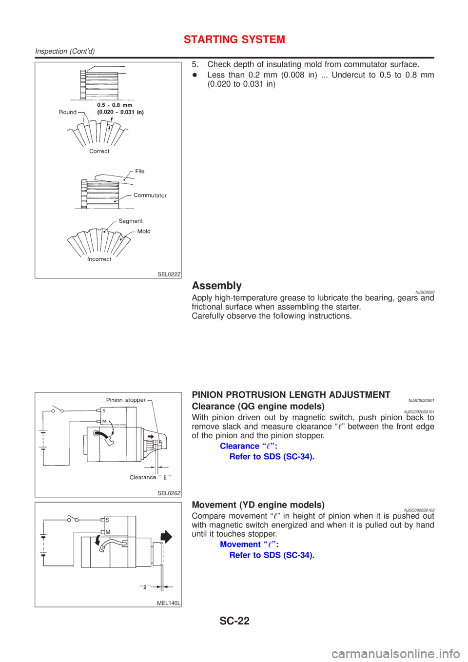
SEL022Z
5. Check depth of insulating mold from commutator surface.
+Less than 0.2 mm (0.008 in) ... Undercut to 0.5 to 0.8 mm
(0.020 to 0.031 in)
AssemblyNJSC0020Apply high-temperature grease to lubricate the bearing, gears and
frictional surface when assembling the starter.
Carefully observe the following instructions.
SEL026Z
PINION PROTRUSION LENGTH ADJUSTMENTNJSC0020S01Clearance (QG engine models)NJSC0020S0101With pinion driven out by magnetic switch, push pinion back to
remove slack and measure clearance ª!º between the front edge
of the pinion and the pinion stopper.
Clearance ª!º:
Refer to SDS (SC-34).
MEL140L
Movement (YD engine models)NJSC0020S0102Compare movement ª!º in height of pinion when it is pushed out
with magnetic switch energized and when it is pulled out by hand
until it touches stopper.
Movement ª!º:
Refer to SDS (SC-34).
STARTING SYSTEM
Inspection (Cont'd)
SC-22
Page 2114 of 2493
WARNING CHIME....................................................... 113
Component Parts and Harness Connector
Location ................................................................... 113
System Description .................................................. 113
Wiring Diagram - CHIME - ...................................... 115
Trouble Diagnoses................................................... 117
FRONT WIPER AND WASHER..................................123
System Description ..................................................123
Wiring Diagram - WIPER - ......................................125
Removal and Installation .........................................127
Washer Nozzle Adjustment .....................................128
Washer Tube Layout ...............................................128
REAR WIPER AND WASHER....................................129
Wiring Diagram - WIP/R -........................................129
Removal and Installation .........................................131
Washer Nozzle Adjustment .....................................131
Washer Tube Layout ...............................................132
HEADLAMP WASHER................................................133
Wiring Diagram - HLC - ...........................................133
Washer Tube Layout ...............................................134
HORN...........................................................................135
Wiring Diagram - HORN - .......................................135
CIGARETTE LIGHTER................................................136
Wiring Diagram - CIGAR -.......................................136
CLOCK.........................................................................137
Wiring Diagram - CLOCK -......................................137
REAR WINDOW DEFOGGER.....................................138
System Description ..................................................138
Schematic ................................................................139
Wiring Diagram - DEF - ...........................................140
Trouble Diagnoses...................................................143
Electrical Components Inspection ...........................146
Filament Check ........................................................147
Filament Repair .......................................................148
AUDIO..........................................................................149
System Description ..................................................149
Schematic ................................................................151
Wiring Diagram - AUDIO - .......................................152
Trouble Diagnoses...................................................160
Inspection.................................................................161
AUDIO ANTENNA.......................................................162
Location of Antenna .................................................162
Antenna Rod Replacement .....................................162
HEATED SEAT............................................................163
Wiring Diagram - H/SEAT - .....................................163
POWER SUNROOF.....................................................165
Wiring Diagram - SROOF - .....................................165
Trouble Diagnoses...................................................166
DOOR MIRROR...........................................................167
Wiring Diagram - MIRROR - ...................................167
POWER WINDOW.......................................................169
System Description ..................................................169Schematic ................................................................171
Wiring Diagram - WINDOW - ..................................172
Trouble Diagnoses...................................................176
POWER DOOR LOCK.................................................177
System Description ..................................................177
Schematic ................................................................178
Wiring Diagram - D/LOCK -.....................................180
Trouble Diagnoses...................................................187
POWER DOOR LOCK - SUPER LOCK -...................196
System Description ..................................................196
Schematic ................................................................198
Wiring Diagram - S/LOCK - .....................................200
Trouble Diagnoses...................................................207
MULTI-REMOTE CONTROL SYSTEM.......................220
System Description ..................................................220
Wiring Diagram - MULTI - .......................................221
Trouble Diagnoses...................................................223
ID Code Entry Procedure ........................................227
Remote Controller Battery Replacement.................228
TIME CONTROL UNIT................................................229
Description ...............................................................229
Trouble Diagnoses...................................................230
Schematic ................................................................232
NATS (NISSAN ANTI-THEFT SYSTEM).....................234
Component Parts and Harness Connetor
Location ...................................................................234
System Description ..................................................234
System Composition ................................................236
Wiring Diagram - NATS -.........................................237
CONSULT-II .............................................................238
Trouble Diagnoses...................................................241
How to Replace NATS IMMU ..................................258
NAVIGATION SYSTEM...............................................259
Precautions ..............................................................259
Component Parts Location ......................................260
System Description ..................................................261
Schematic ................................................................269
Wiring Diagram - NAVI - ..........................................270
Self-diagnosis Mode ................................................278
Confirmation/Adjustment Mode ...............................281
Control Panel Mode .................................................293
Guide Volume Setting ..............................................300
Anti-theft System .....................................................301
CONSULT-II .............................................................302
Trouble Diagnoses...................................................303
This Condition Is Not Abnormal...............................309
Program Loading .....................................................318
ELECTRICAL UNITS LOCATION...............................319
Engine Compartment ...............................................319
Passenger Compartment/LHD Models ....................320
Passenger Compartment/RHD Models ...................322
CONTENTS(Cont'd)
EL-2
Page 2154 of 2493
SEL921W
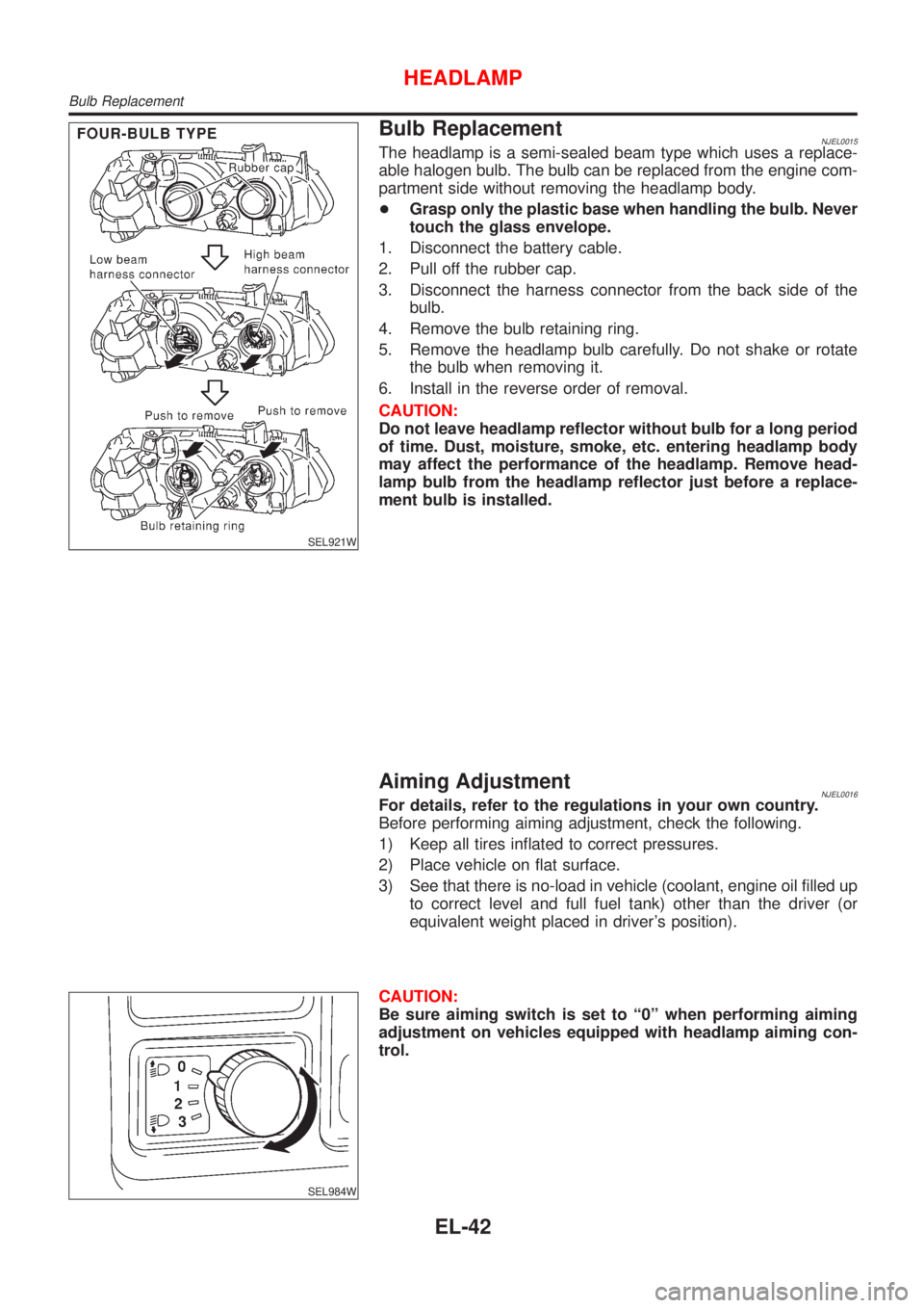
Bulb ReplacementNJEL0015The headlamp is a semi-sealed beam type which uses a replace-
able halogen bulb. The bulb can be replaced from the engine com-
partment side without removing the headlamp body.
+Grasp only the plastic base when handling the bulb. Never
touch the glass envelope.
1. Disconnect the battery cable.
2. Pull off the rubber cap.
3. Disconnect the harness connector from the back side of the
bulb.
4. Remove the bulb retaining ring.
5. Remove the headlamp bulb carefully. Do not shake or rotate
the bulb when removing it.
6. Install in the reverse order of removal.
CAUTION:
Do not leave headlamp reflector without bulb for a long period
of time. Dust, moisture, smoke, etc. entering headlamp body
may affect the performance of the headlamp. Remove head-
lamp bulb from the headlamp reflector just before a replace-
ment bulb is installed.
Aiming AdjustmentNJEL0016For details, refer to the regulations in your own country.
Before performing aiming adjustment, check the following.
1) Keep all tires inflated to correct pressures.
2) Place vehicle on flat surface.
3) See that there is no-load in vehicle (coolant, engine oil filled up
to correct level and full fuel tank) other than the driver (or
equivalent weight placed in driver's position).
SEL984W
CAUTION:
Be sure aiming switch is set to ª0º when performing aiming
adjustment on vehicles equipped with headlamp aiming con-
trol.
HEADLAMP
Bulb Replacement
EL-42
Page 2212 of 2493
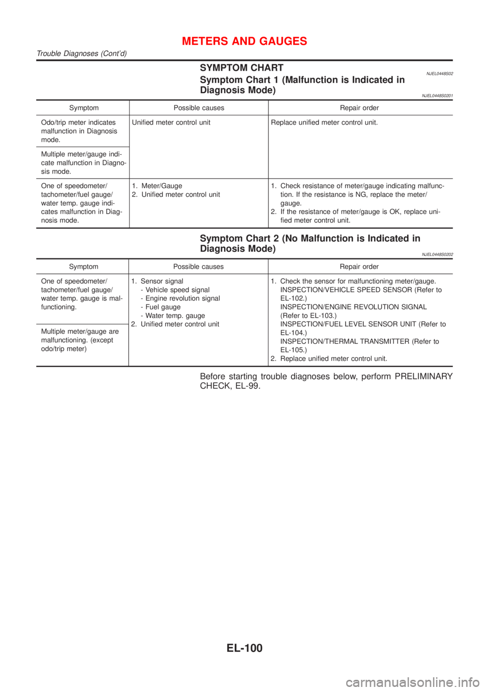
SYMPTOM CHARTNJEL0448S02Symptom Chart 1 (Malfunction is Indicated in
Diagnosis Mode)
NJEL0448S0201
Symptom Possible causes Repair order
Odo/trip meter indicates
malfunction in Diagnosis
mode.Unified meter control unit Replace unified meter control unit.
Multiple meter/gauge indi-
cate malfunction in Diagno-
sis mode.
One of speedometer/
tachometer/fuel gauge/
water temp. gauge indi-
cates malfunction in Diag-
nosis mode.1. Meter/Gauge
2. Unified meter control unit1. Check resistance of meter/gauge indicating malfunc-
tion. If the resistance is NG, replace the meter/
gauge.
2. If the resistance of meter/gauge is OK, replace uni-
fied meter control unit.
Symptom Chart 2 (No Malfunction is Indicated in
Diagnosis Mode)
NJEL0448S0202
Symptom Possible causes Repair order
One of speedometer/
tachometer/fuel gauge/
water temp. gauge is mal-
functioning.1. Sensor signal
- Vehicle speed signal
- Engine revolution signal
- Fuel gauge
- Water temp. gauge
2. Unified meter control unit1. Check the sensor for malfunctioning meter/gauge.
INSPECTION/VEHICLE SPEED SENSOR (Refer to
EL-102.)
INSPECTION/ENGINE REVOLUTION SIGNAL
(Refer to EL-103.)
INSPECTION/FUEL LEVEL SENSOR UNIT (Refer to
EL-104.)
INSPECTION/THERMAL TRANSMITTER (Refer to
EL-105.)
2. Replace unified meter control unit. Multiple meter/gauge are
malfunctioning. (except
odo/trip meter)
Before starting trouble diagnoses below, perform PRELIMINARY
CHECK, EL-99.
METERS AND GAUGES
Trouble Diagnoses (Cont'd)
EL-100
Page 2215 of 2493
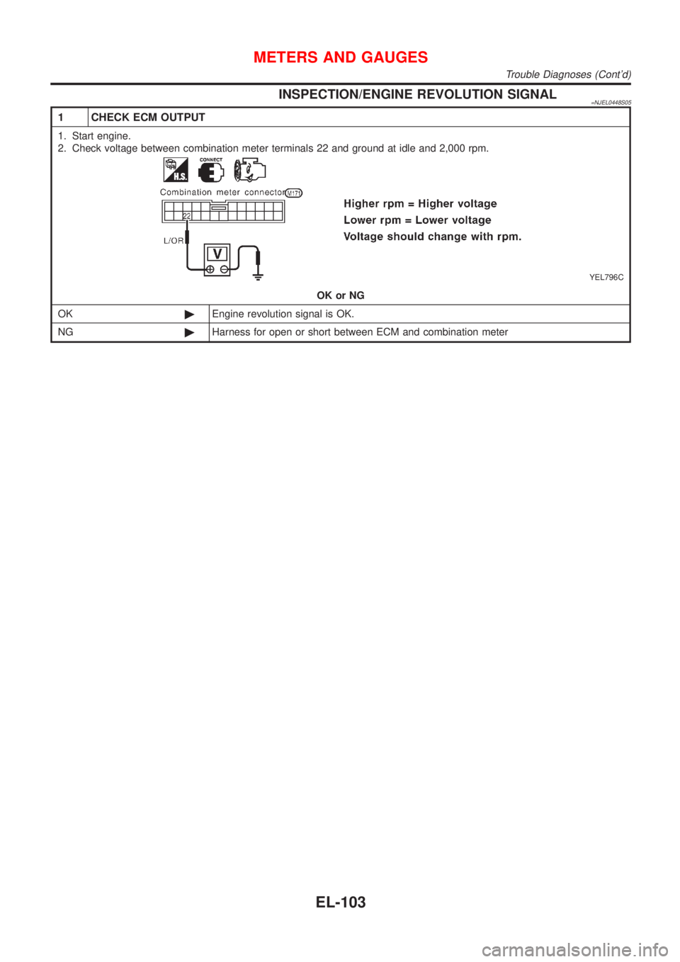
INSPECTION/ENGINE REVOLUTION SIGNAL=NJEL0448S05
1 CHECK ECM OUTPUT
1. Start engine.
2. Check voltage between combination meter terminals 22 and ground at idle and 2,000 rpm.
YEL796C
OK or NG
OK©Engine revolution signal is OK.
NG©Harness for open or short between ECM and combination meter
METERS AND GAUGES
Trouble Diagnoses (Cont'd)
EL-103
Page 2224 of 2493
NEL796
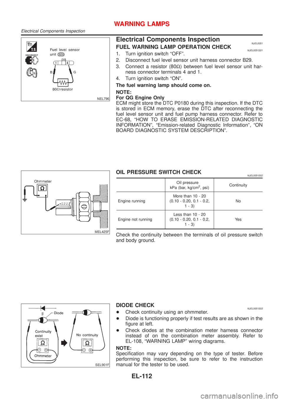
Electrical Components InspectionNJEL0051FUEL WARNING LAMP OPERATION CHECKNJEL0051S011. Turn ignition switch ªOFFº.
2. Disconnect fuel level sensor unit harness connector B29.
3. Connect a resistor (80W) between fuel level sensor unit har-
ness connector terminals 4 and 1.
4. Turn ignition switch ªONº.
The fuel warning lamp should come on.
NOTE:
For QG Engine Only
ECM might store the DTC P0180 during this inspection. If the DTC
is stored in ECM memory, erase the DTC after reconnecting the
fuel level sensor unit and fuel pump harness connector. Refer to
EC-68, ªHOW TO ERASE EMISSION-RELATED DIAGNOSTIC
INFORMATIONº, ªEmission-related Diagnostic Informationº, ªON
BOARD DIAGNOSTIC SYSTEM DESCRIPTIONº.
MEL425F
OIL PRESSURE SWITCH CHECKNJEL0051S02
Oil pressure
kPa (bar, kg/cm2, psi)Continuity
Engine runningMore than 10 - 20
(0.10 - 0.20, 0.1 - 0.2,
1-3)No
Engine not runningLess than 10 - 20
(0.10 - 0.20, 0.1 - 0.2,
1-3)Ye s
Check the continuity between the terminals of oil pressure switch
and body ground.
SEL901F
DIODE CHECKNJEL0051S03+Check continuity using an ohmmeter.
+Diode is functioning properly if test results are as shown in the
figure at left.
+Check diodes at the combination meter harness connector
instead of on the combination meter assembly. Refer to
EL-108, ªWARNING LAMPº wiring diagrams.
NOTE:
Specification may vary depending on the type of tester. Before
performing this inspection, be sure to refer to the instruction
manual for the tester to be used.
WARNING LAMPS
Electrical Components Inspection
EL-112