2001 NISSAN ALMERA N16 check engine
[x] Cancel search: check enginePage 641 of 2493
Main 12 Causes of Overheating=NJEC0492
Engine Step Inspection item Equipment Standard Reference page
OFF 1+Blocked radiator
+Blocked condenser
+Blocked radiator grille
+Blocked bumper+Visual No blocking Ð
2+Coolant mixture+Coolant tester 50 - 50% coolant mixture See MA-20, ªRECOM-
MENDED FLUIDS AND
LUBRICANTSº.
3+Coolant level+Visual Coolant up to MAX level
in reservoir tank and
radiator filler neckSee LC-17, ªChanging
Engine Coolantº.
4+Radiator cap+Pressure tester 59 - 98 kPa
(0.59 - 0.98 bar, 0.6 - 1.0
kg/cm
2,9-14psi) (Limit)See LC-10, ªSystem
Checkº.
ON*
25+Coolant leaks+Visual No leaks See LC-10, ªSystem
Checkº.
ON*
26+Thermostat+Touch the upper and
lower radiator hosesBoth hoses should be
hotSee LC-15, ªThermostatº
and LC-16, ªRadiatorº.
ON*
17+Cooling fan+CONSULT-II Operating See ªTROUBLE DIAG-
NOSIS FOR OVER-
HEATº (EC-334).
OFF 8+Combustion gas leak+Color checker chemi-
cal tester 4 Gas ana-
lyzerNegative Ð
ON*
39+Coolant temperature
gauge+Visual Gauge less than 3/4
when drivingÐ
+Coolant overflow to
reservoir tank+Visual No overflow during driv-
ing and idlingSee LC-17, ªChanging
Engine Coolantº.
OFF*
410+Coolant return from
reservoir tank to radia-
tor+Visual Should be initial level in
reservoir tankSee LC-18, ªRefilling
Engine Coolantº.
OFF 11+Cylinder head+Straight gauge feeler
gauge0.1 mm (0.004 in) Maxi-
mum distortion (warping)See EM-36, ªInspectionº,
ªCYLINDER HEADº.
12+Cylinder block and
pistons+Visual No scuffing on cylinder
walls or pistonSee EM-54, ªInspectionº,
ªCYLINDER BLOCKº.
*1: Turn the ignition switch ON.
*2: Engine running at 3,000 rpm for 10 minutes.
*3: Drive at 90 km/h (55 MPH) for 30 minutes and then let idle for 10 minutes.
*4: After 60 minutes of cool down time.
For more information, refer to LC-23, ª OVERHEATING CAUSE ANALYSISº.
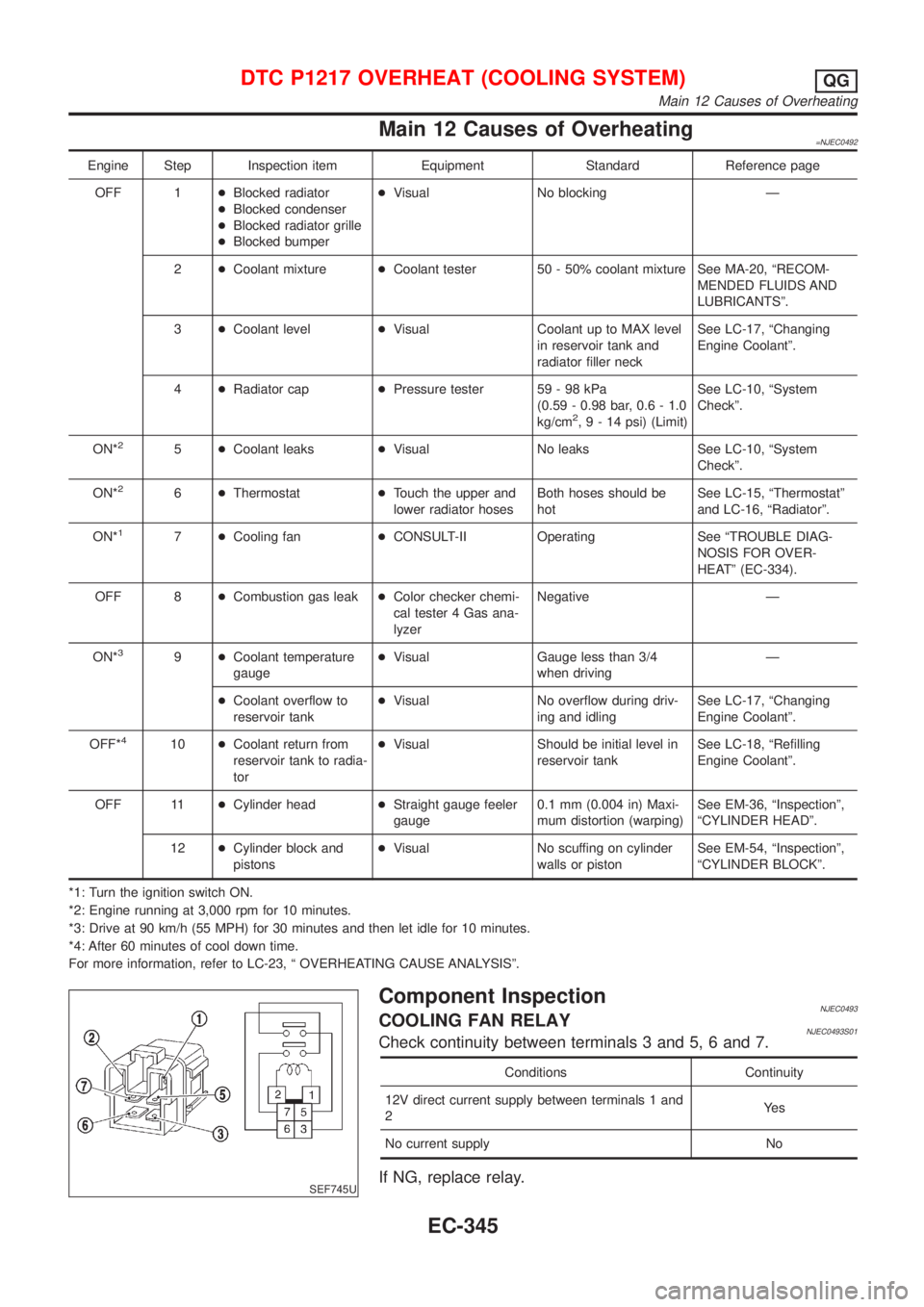
SEF745U
Component InspectionNJEC0493COOLING FAN RELAYNJEC0493S01Check continuity between terminals 3 and 5, 6 and 7.
Conditions Continuity
12V direct current supply between terminals 1 and
2Ye s
No current supply No
If NG, replace relay.
DTC P1217 OVERHEAT (COOLING SYSTEM)QG
Main 12 Causes of Overheating
EC-345
Page 643 of 2493
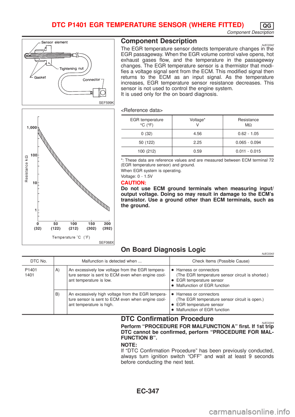
SEF599K
Component DescriptionNJEC0342The EGR temperature sensor detects temperature changes in the
EGR passageway. When the EGR volume control valve opens, hot
exhaust gases flow, and the temperature in the passageway
changes. The EGR temperature sensor is a thermistor that modi-
fies a voltage signal sent from the ECM. This modified signal then
returns to the ECM as an input signal. As the temperature
increases, EGR temperature sensor resistance decreases. This
sensor is not used to control the engine system.
It is used only for the on board diagnosis.
SEF068X
EGR temperature
ÉC (ÉF)Voltage*
VResistance
MW
0 (32) 4.56 0.62 - 1.05
50 (122) 2.25 0.065 - 0.094
100 (212) 0.59 0.011 - 0.015
*: These data are reference values and are measured between ECM terminal 72
(EGR temperature sensor) and ground.
When EGR system is operating.
Voltage: 0 - 1.5V
CAUTION:
Do not use ECM ground terminals when measuring input/
output voltage. Doing so may result in damage to the ECM's
transistor. Use a ground other than ECM terminals, such as
the ground.
On Board Diagnosis LogicNJEC0343
DTC No. Malfunction is detected when ... Check Items (Possible Cause)
P1401
1401A) An excessively low voltage from the EGR tempera-
ture sensor is sent to ECM even when engine cool-
ant temperature is low.+Harness or connectors
(The EGR temperature sensor circuit is shorted.)
+EGR temperature sensor
+Malfunction of EGR function
B) An excessively high voltage from the EGR tempera-
ture sensor is sent to ECM even when engine cool-
ant temperature is high.+Harness or connectors
(The EGR temperature sensor circuit is open.)
+EGR temperature sensor
+Malfunction of EGR function
DTC Confirmation ProcedureNJEC0344Perform ªPROCEDURE FOR MALFUNCTION Aº first. If 1st trip
DTC cannot be confirmed, perform ªPROCEDURE FOR MAL-
FUNCTION Bº.
NOTE:
If ªDTC Confirmation Procedureº has been previously conducted,
always turn ignition switch ªOFFº and wait at least 9 seconds
before conducting the next test.
DTC P1401 EGR TEMPERATURE SENSOR (WHERE FITTED)QG
Component Description
EC-347
Page 644 of 2493
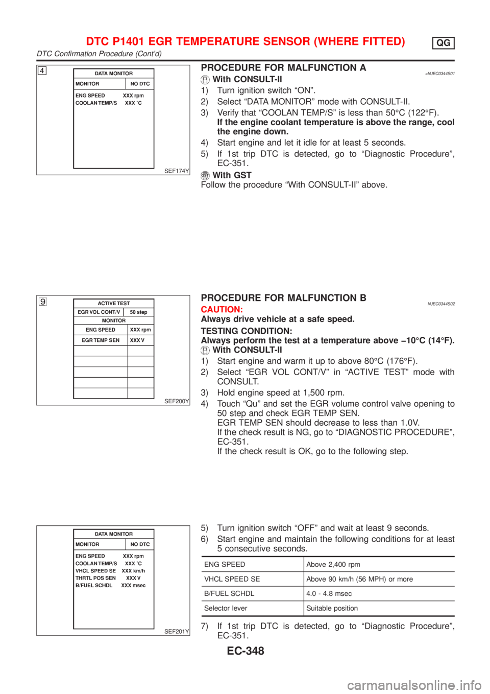
SEF174Y
PROCEDURE FOR MALFUNCTION A=NJEC0344S01With CONSULT-II
1) Turn ignition switch ªONº.
2) Select ªDATA MONITORº mode with CONSULT-II.
3) Verify that ªCOOLAN TEMP/Sº is less than 50ÉC (122ÉF).
If the engine coolant temperature is above the range, cool
the engine down.
4) Start engine and let it idle for at least 5 seconds.
5) If 1st trip DTC is detected, go to ªDiagnostic Procedureº,
EC-351.
With GST
Follow the procedure ªWith CONSULT-IIº above.
SEF200Y
PROCEDURE FOR MALFUNCTION BNJEC0344S02CAUTION:
Always drive vehicle at a safe speed.
TESTING CONDITION:
Always perform the test at a temperature above þ10ÉC (14ÉF).
With CONSULT-II
1) Start engine and warm it up to above 80ÉC (176ÉF).
2) Select ªEGR VOL CONT/Vº in ªACTIVE TESTº mode with
CONSULT.
3) Hold engine speed at 1,500 rpm.
4) Touch ªQuº and set the EGR volume control valve opening to
50 step and check EGR TEMP SEN.
EGR TEMP SEN should decrease to less than 1.0V.
If the check result is NG, go to ªDIAGNOSTIC PROCEDUREº,
EC-351.
If the check result is OK, go to the following step.
SEF201Y
5) Turn ignition switch ªOFFº and wait at least 9 seconds.
6) Start engine and maintain the following conditions for at least
5 consecutive seconds.
ENG SPEED Above 2,400 rpm
VHCL SPEED SE Above 90 km/h (56 MPH) or more
B/FUEL SCHDL 4.0 - 4.8 msec
Selector lever Suitable position
7) If 1st trip DTC is detected, go to ªDiagnostic Procedureº,
EC-351.
DTC P1401 EGR TEMPERATURE SENSOR (WHERE FITTED)QG
DTC Confirmation Procedure (Cont'd)
EC-348
Page 647 of 2493
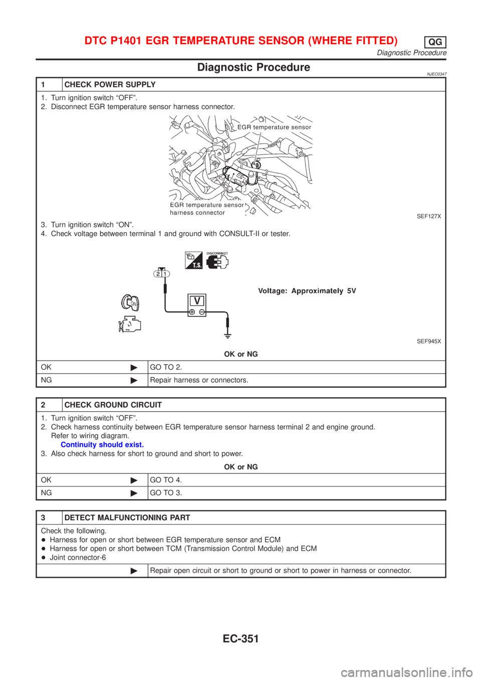
Diagnostic ProcedureNJEC0347
1 CHECK POWER SUPPLY
1. Turn ignition switch ªOFFº.
2. Disconnect EGR temperature sensor harness connector.
SEF127X
3. Turn ignition switch ªONº.
4. Check voltage between terminal 1 and ground with CONSULT-II or tester.
SEF945X
OK or NG
OK©GO TO 2.
NG©Repair harness or connectors.
2 CHECK GROUND CIRCUIT
1. Turn ignition switch ªOFFº.
2. Check harness continuity between EGR temperature sensor harness terminal 2 and engine ground.
Refer to wiring diagram.
Continuity should exist.
3. Also check harness for short to ground and short to power.
OK or NG
OK©GO TO 4.
NG©GO TO 3.
3 DETECT MALFUNCTIONING PART
Check the following.
+Harness for open or short between EGR temperature sensor and ECM
+Harness for open or short between TCM (Transmission Control Module) and ECM
+Joint connector-6
©Repair open circuit or short to ground or short to power in harness or connector.
DTC P1401 EGR TEMPERATURE SENSOR (WHERE FITTED)QG
Diagnostic Procedure
EC-351
Page 651 of 2493
DTC No. Malfunction is detected when ... Check Items (Possible Cause)
P1402
1402+EGR flow is detected under conditions that do not call for
EGR.+Harness or connectors
(The valve circuit is open or shorted.)
+EGR volume control valve leaking or stuck open
+EGR temperature sensor
SEF202Y
SEF851Y
SEF852Y
SEF236Y
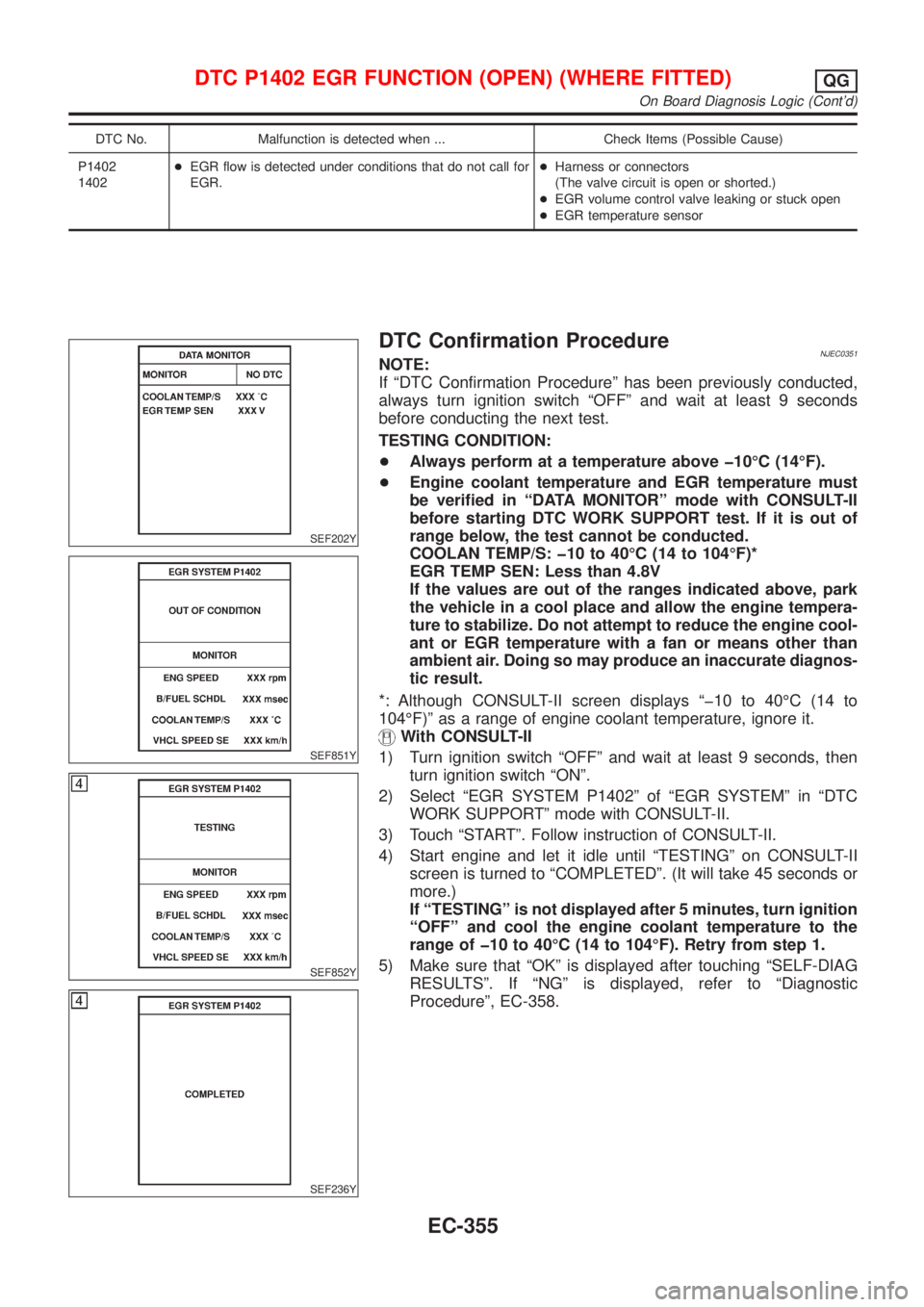
DTC Confirmation ProcedureNJEC0351NOTE:
If ªDTC Confirmation Procedureº has been previously conducted,
always turn ignition switch ªOFFº and wait at least 9 seconds
before conducting the next test.
TESTING CONDITION:
+Always perform at a temperature above þ10ÉC (14ÉF).
+Engine coolant temperature and EGR temperature must
be verified in ªDATA MONITORº mode with CONSULT-II
before starting DTC WORK SUPPORT test. If it is out of
range below, the test cannot be conducted.
COOLAN TEMP/S: þ10 to 40ÉC (14 to 104ÉF)*
EGR TEMP SEN: Less than 4.8V
If the values are out of the ranges indicated above, park
the vehicle in a cool place and allow the engine tempera-
ture to stabilize. Do not attempt to reduce the engine cool-
ant or EGR temperature with a fan or means other than
ambient air. Doing so may produce an inaccurate diagnos-
tic result.
*: Although CONSULT-II screen displays ªþ10 to 40ÉC (14 to
104ÉF)º as a range of engine coolant temperature, ignore it.
With CONSULT-II
1) Turn ignition switch ªOFFº and wait at least 9 seconds, then
turn ignition switch ªONº.
2) Select ªEGR SYSTEM P1402º of ªEGR SYSTEMº in ªDTC
WORK SUPPORTº mode with CONSULT-II.
3) Touch ªSTARTº. Follow instruction of CONSULT-II.
4) Start engine and let it idle until ªTESTINGº on CONSULT-II
screen is turned to ªCOMPLETEDº. (It will take 45 seconds or
more.)
If ªTESTINGº is not displayed after 5 minutes, turn ignition
ªOFFº and cool the engine coolant temperature to the
range of þ10 to 40ÉC (14 to 104ÉF). Retry from step 1.
5) Make sure that ªOKº is displayed after touching ªSELF-DIAG
RESULTSº. If ªNGº is displayed, refer to ªDiagnostic
Procedureº, EC-358.
DTC P1402 EGR FUNCTION (OPEN) (WHERE FITTED)QG
On Board Diagnosis Logic (Cont'd)
EC-355
Page 652 of 2493
SEF947X
With GST
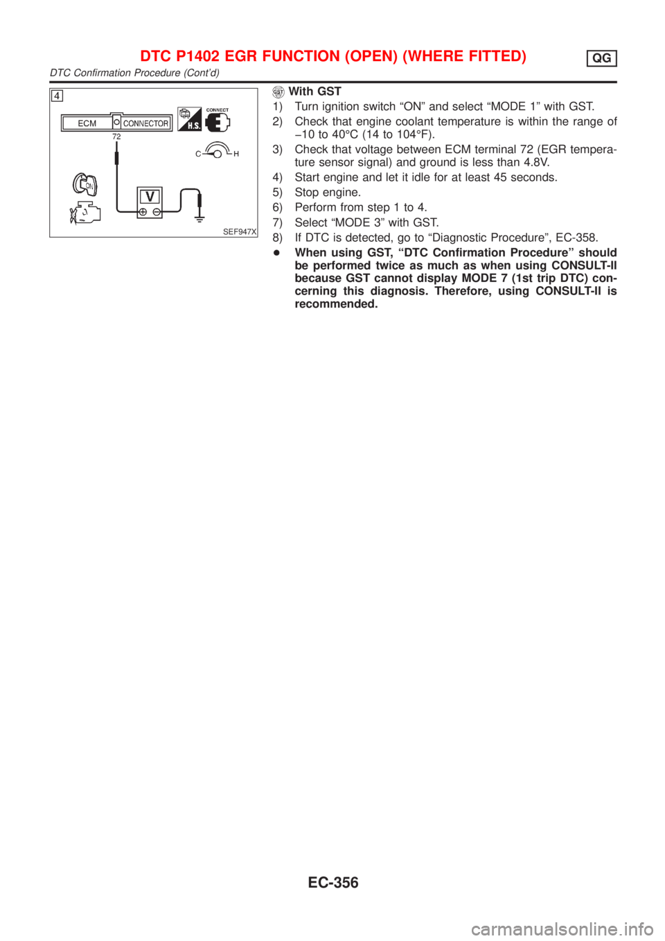
1) Turn ignition switch ªONº and select ªMODE 1º with GST.
2) Check that engine coolant temperature is within the range of
þ10 to 40ÉC (14 to 104ÉF).
3) Check that voltage between ECM terminal 72 (EGR tempera-
ture sensor signal) and ground is less than 4.8V.
4) Start engine and let it idle for at least 45 seconds.
5) Stop engine.
6) Perform from step 1 to 4.
7) Select ªMODE 3º with GST.
8) If DTC is detected, go to ªDiagnostic Procedureº, EC-358.
+When using GST, ªDTC Confirmation Procedureº should
be performed twice as much as when using CONSULT-II
because GST cannot display MODE 7 (1st trip DTC) con-
cerning this diagnosis. Therefore, using CONSULT-II is
recommended.
DTC P1402 EGR FUNCTION (OPEN) (WHERE FITTED)QG
DTC Confirmation Procedure (Cont'd)
EC-356
Page 657 of 2493

System DescriptionNJEC0573The malfunction information related to A/T (Automatic Transaxle) is transferred through the line (circuit) from
TCM (Transmission Control Module) to ECM. Therefore, be sure to erase the malfunction information such as
DTC not only in TCM (Transmission Control Module) but also ECM after the A/T related repair.
ECM Terminals and Reference ValueNJEC0574Specification data are reference values and are measured between each terminal and ground.
CAUTION:
Do not use ECM ground terminals when measuring input/output voltage. Doing so may result in dam-
age to the ECM's transistor. Use a ground other than ECM terminals, such as the ground.
TERMI-
NAL
NO.WIRE
COLORITEM CONDITION DATA (DC Voltage)
91 PU A/T check signal[Ignition switch ªONº]0 - Approximately 5V
On Board Diagnosis LogicNJEC0575
DTC No. Malfunction is detected when ... Check Items (Possible Cause)
P1605
1605+An incorrect signal from TCM (Transmission Control
Module) is sent to ECM.+Harness or connectors
[The communication line circuit between ECM
and TCM (Transmission Control Module) is open
or shorted.]
+Dead (Weak) battery
+TCM (Transmission Control Module)
SEF058Y
DTC Confirmation ProcedureNJEC0576NOTE:
If ªDTC CONFIRMATION PROCEDUREº has been previously
conducted, always turn ignition switch ªOFFº and wait at least 9
seconds before conducting the next test.
With CONSULT-II
1) Turn ignition switch ªONº.
2) Select ªDATA MONITORº mode with CONSULT-II.
3) Start engine and let it idle for at least 40 seconds.
4) If 1st trip DTC is detected, go to ªDiagnostic Procedureº,
EC-363.
With GST
Follow the procedure ªWith CONSULT-IIº above.
DTC P1605 A/T DIAGNOSIS COMMUNICATION LINEQG
System Description
EC-361
Page 660 of 2493
SEF740W
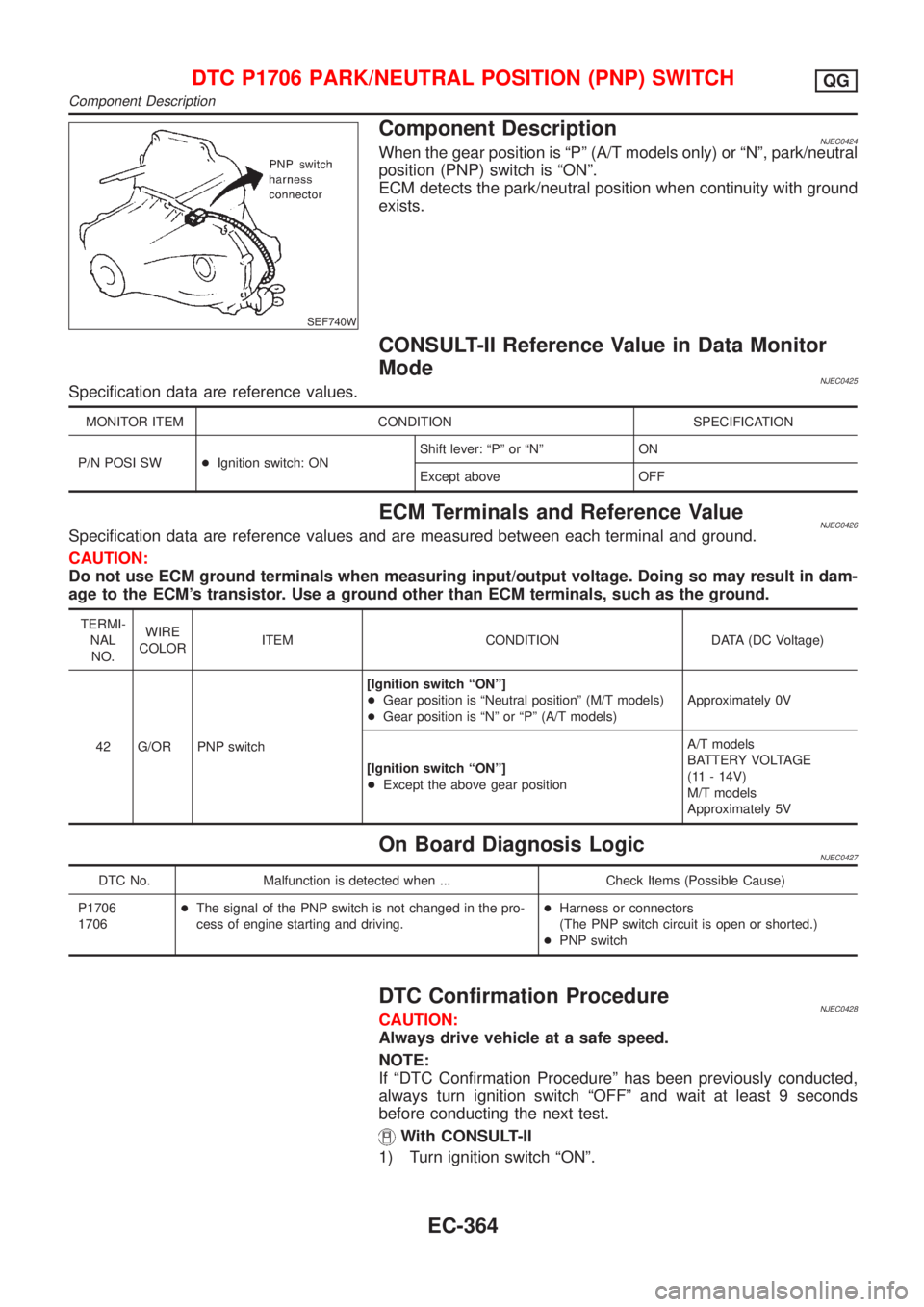
Component DescriptionNJEC0424When the gear position is ªPº (A/T models only) or ªNº, park/neutral
position (PNP) switch is ªONº.
ECM detects the park/neutral position when continuity with ground
exists.
CONSULT-II Reference Value in Data Monitor
Mode
NJEC0425Specification data are reference values.
MONITOR ITEM CONDITION SPECIFICATION
P/N POSI SW+Ignition switch: ONShift lever: ªPº or ªNº ON
Except above OFF
ECM Terminals and Reference ValueNJEC0426Specification data are reference values and are measured between each terminal and ground.
CAUTION:
Do not use ECM ground terminals when measuring input/output voltage. Doing so may result in dam-
age to the ECM's transistor. Use a ground other than ECM terminals, such as the ground.
TERMI-
NAL
NO.WIRE
COLORITEM CONDITION DATA (DC Voltage)
42 G/OR PNP switch[Ignition switch ªONº]
+Gear position is ªNeutral positionº (M/T models)
+Gear position is ªNº or ªPº (A/T models)Approximately 0V
[Ignition switch ªONº]
+Except the above gear positionA/T models
BATTERY VOLTAGE
(11 - 14V)
M/T models
Approximately 5V
On Board Diagnosis LogicNJEC0427
DTC No. Malfunction is detected when ... Check Items (Possible Cause)
P1706
1706+The signal of the PNP switch is not changed in the pro-
cess of engine starting and driving.+Harness or connectors
(The PNP switch circuit is open or shorted.)
+PNP switch
DTC Confirmation ProcedureNJEC0428CAUTION:
Always drive vehicle at a safe speed.
NOTE:
If ªDTC Confirmation Procedureº has been previously conducted,
always turn ignition switch ªOFFº and wait at least 9 seconds
before conducting the next test.
With CONSULT-II
1) Turn ignition switch ªONº.
DTC P1706 PARK/NEUTRAL POSITION (PNP) SWITCHQG
Component Description
EC-364